Sign In
Upload
Manuals
Brands
Milnor Manuals
Washer
72044SR2
Milnor 72044SR2 Manuals
Manuals and User Guides for Milnor 72044SR2. We have
3
Milnor 72044SR2 manuals available for free PDF download: Mechanical Parts And Service, Installation Manual, Operator's Manual
Milnor 72044SR2 Mechanical Parts And Service (175 pages)
Washer Extractor
Brand:
Milnor
| Category:
Washer
| Size: 14.53 MB
Table of Contents
Table of Contents
3
General Service & Safety-Related Components
9
Limited Standard Warranty
10
How to Get the Necessary Repair Components
11
Trademarks
11
Table 1 Trademarks
11
Safety - Divided Cylinder and Staph Guard
12
Safety Alert Messages-Internal Electrical and Mechanical Hazards
12
Safety Alert Messages-External Mechanical Hazards
12
Safety Alert Messages-Cylinder and Processing Hazards
12
Safety Alert Messages-Unsafe Conditions
13
Damage and Malfunction Hazards
13
Hazards Resulting from Inoperative Safety Devices
13
Hazards Resulting from Damaged Mechanical Devices
14
(See also Service Hazards Throughout Manuals)
15
Careless Operation Hazards-Vital Information for Operator Personnel (See also Operator Hazards Throughout Manual)
15
Careless Servicing Hazards-Vital Information for Service Personnel
15
Careless Use Hazards
15
Safety Placard Use and Placement
16
60044Sr2, 60044Sr3, 72044Sr2
16
Safety Placard Use and Placement ISO
18
60044Sr2, 60044Sr3, 72044Sr2
18
Belt Guards 72044SR2
20
Figure 1 Soil Side
20
Figure 2 Clean Side
21
Torque Requirements for Fasteners
23
Torque Values
23
Fasteners Made of Carbon Steel
23
Figure
23
Figure 3 the Bolts in Milnor ® Equipment
23
Table 5 Torque Values for Standard Fasteners with Maximum 5/16-Inch Diameters and no Lubricant
23
Table 6 Torque Values for Standard Fasteners Larger than 5/16-Inch Diameters and no Lubricant
23
Without a Threadlocker
23
Table 7 Torque Values for Plated Fasteners with Maximum 5/16-Inch Diameters and no Lubricant
24
Table 8 Torque Values for Plated Fasteners Larger than 5/16-Inch Diameters and no Lubricant
24
Table 9 Threadlocker by the Diameter of the Bolt (See below Note )
25
With a Threadlocker
25
Table 11 Torque Values if You Apply Loctite 242
26
Table 13 Torque Values if You Apply Loctite 272 (High-Temperature)
26
Stainless Steel Fasteners
27
Table 14 Torque Values if You Apply Loctite 277
27
Table 15 Torque Values for Stainless Steel Fasteners 5/16-Inch and Smaller
27
Table 16 Torque Values for Stainless Steel Fasteners Larger than 5/16-Inch
27
Preparation
28
How to Apply a Threadlocker
28
Figure 4 Apply Threadlocker in a Blind Hole
28
Blind Holes
29
Figure 5 Apply Threadlocker in a through Hole
29
Figure 6 Use Heat for Disassembly of Fasteners with Threadlocker
29
Through Holes
29
Drive Assemblies
30
Drive Pulley and Belt Maintenance
30
Pulley Requirements
30
Figure 7. Examples of Drives this Instruction Applies To: One or more V-Belts, Attached V-Belts and Tooth Belts
30
Condition of Grooves on Pulleys
31
Figure 8 Pulley Groove Condition
31
Pulley and Shaft Position
31
Figure 9 Pulley and Shaft Position
32
Keep Run-Out in Tolerance
32
Belt Requirements
33
Figure 10 Run-Out
33
Figure 11 Typical Pulley Assembly
33
Condition of Belts
34
Figure 12 Types of Belt Damage
34
Tension of Belts
35
The Pulleys Must Stay Aligned When You Adjust the Belt Tension
35
How to Do Maintenance on Pulleys and Belts
36
Figure 13 a Tension Mechanism that will Not Change the Angle of the Pulleys
36
Figure 14 some Pairs of Tension Mechanisms that Can Change the Angle of the
36
Table 17 Typical Tools for Pulley and Belt Maintenance
36
Typical Steps to Replace Pulleys and Belts
37
Examples of Procedures Used at the Milnor ® Factory to Align Pulleys
38
Figure 15 Use a Straight Edge, a String, or a Laser to Make Sure that All Pulleys Are in the same Plane
38
Disk Brake Maintenance
39
The Inspection of the Brake
41
How to Do a Friction Pad Replacement
42
How to Do a Caliper Overhaul
44
Circuit
45
Cylinder
47
Operation of Brake Systems
50
How to Apply the Brake for Machines with a "Break Release" Output
50
How the Brake Operates on Divided Cylinder Machines
51
How to Apply and then Release the Brake Quickly
51
How to Release the Brake for Machines with a "Brake Release" Output
51
The Second Brake
52
Drive Chart
53
72044Sr2, Sr3
53
Figure
53
Figure
54
Drive Base
56
Jackshaft
61
Detail Views
62
Air Clutch
64
Reducer Air Seal
65
Upper Brake Assembly
66
72044Sr2/Sr3
66
Main Bearing and Seal Replacement for Divided Cylinder Machines
68
Removing the Bearing (Front or Rear)
69
(Front or Rear)
70
Precautions for Bearing Replacement
71
Replacing the Bearing Housing, Seal Sleeve, and Seals (Front or Rear)
72
Measuring Unmounted Clearance and Setting Bearing (Front or Rear)
74
Tightening Bearing(S) (Front And/Or Rear)
76
Shaft and Bearing Components
78
72044Wr2, 72044Wr3, 72044Sr2, 72044Sr3
78
Autospot Drive Motor
82
Inch Idler Shaft Bearing
84
Figure
84
Lower Disc Brake Installation
86
Lower Disc Brake Split Bearing Parts and Assembly
91
6044Sr2, 72044Sr2/Sr3
92
Assembly Procedure
92
Frame & Suspension
96
Suspension Adjustments for Divided Cylinder Machines
96
How Shell Adjustments Are Made
96
Shell Hanging Dimensions and Adjustment Procedures
97
Figure
98
Push-Down Travel Dimensions and Adjustment Procedures
99
42" Divided Cylinder Machines
99
60" Divided Cylinder Machines
100
Hold down Adjustment
102
6044Sr2/Sr3, 6044Wr2/Wr3, 72044Sr2/Sr3, 72044Wr2/Wr3
102
Push down Components
104
72044Wr2, Sr2
104
Suspension Cylinder Assemblies
107
Suspension Cylinder Locations
110
Shell, Cylinder & Door
112
Shell Doors
114
72044Wr3, 72044Sr2
114
Door Latch
117
Cylinder Assembly and Cylinder Door Installation
118
6044Sr2, 7244Sr2
118
Installed View
120
Cylinder Doors 3 Pocket
123
7244Wr3, 7244Sr3
123
Section Views
123
Cylinder Doors
124
Figure
125
Staph Guard
128
Staph Barrier Cleanside
130
6044Sr2, 72044Sr2
130
60044Sr2, 72044Sr2
132
Exploded Vew
132
Installed View
133
Control & Sensing
135
Air Operated Autospot and Sensing Unit
136
Excursion Switch
140
6044Sr2, 6044Sr3, 7244Sr2
140
Air Chamber Level Switch
141
42044Wr2,Wr3,Sr2,Sr3; 6044Wr2,Wr3,Sr2, Sr3; 72044Wr2
141
Wr3, Sr2, Sr3
141
Temperature Probe
142
6044Wr2,Wr3,Sr2 72044Wr2,Wr3,Sr3
142
Centrifugal Switch Assembly
143
72044Sr2, 72044Sr3
143
Vibration Safety Switch Adjustments
144
What the Vibration Safety Switch Does
144
Adjustments
144
Vibration Safety Switch
146
Chemical Supply Devices
147
Peristaltic Supply Manifold
148
72044Wr2, 72044Sr2
148
Soap Chute 72044SR2
150
Five Compartment Supply
152
72044Sp2, 72044Sr2, 7244Wp2, 7244Wr2
152
Water & Steam
157
Water Inlets 72044SR2
158
Steam Components 72044SR2
161
42044Wr2/Wr3/Sr2/Sr3; 60044Wr2/Wr3/Sr2/Sr3
164
72044Wr2/Wr3/Sr2/Sr3
164
8"X10" Stainless Dump Valve
165
Drain Valve Body with Two Valves
167
72044Wr2, 72044Sr2
167
Pneumatic
170
Servicing Air Cylinders
170
Using Threaded Rods
170
Figure
171
Brake Air Cylinder
174
Advertisement
Milnor 72044SR2 Operator's Manual (48 pages)
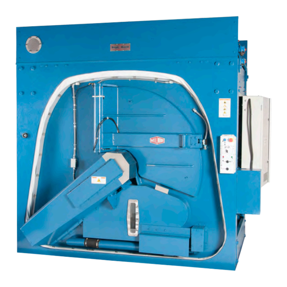
Divided-cylinder, Staph Guard MilTouch-EX Washer-extractor
Brand:
Milnor
| Category:
Washer
| Size: 1.51 MB
Table of Contents
Table of Contents
8
Preface
11
About this Operator Guide and this Miltouch™ Washer-Extractor
11
Controls
12
About Staph Guard ® Machines
12
Physical Controls
12
Figure 1 Flow of Goods on Staph Guard ® Machines
12
Figure 2 Soiled-Side Control Panel with Two-Pocket Autospot™ Selector Switch
13
Figure 3 Clean-Side Control Panel with Two-Pocket Autospot™ Selector Switch
13
Main Controls
14
Figure 4 Autospot™ Selector Switch for Three-Pocket Machines
14
Figure 5 Resume or Cancel the Formula
14
Soiled-Side Controls
15
Clean-Side Controls
16
Emergency Stop Switch (Locking Push Button)
16
How to Use the Miltouch™ Controller
17
The Home Display
17
Figure 6 Emergency Stop Switch
17
About the Start Button
18
Figure 7 the Home Display
18
Normal Operation
20
Safety and Best Practice When Loading and Unloading
20
Loading and Unloading Safety
20
Load Size Best Practice
20
Weighing Goods
21
Apply Control Power
22
About Outer and Inner Doors
22
Align the Cylinder Pockets
22
Open the Outer Door (Air Unlatch)
23
Open the Inner Doors
23
Figure 8 Air-Unlatch Door
23
Figure 9 Inner Door Weld Dot
23
Figure 10 Inner and Outer Door Aligned
23
Load the First Pocket
26
To Load the First Pocket (Optional Weighing System)
26
Figure 11 Weighing System Display
26
To Load the First Pocket (Separate Laundry Scale)
27
Close the Inner Door
28
Close the Outer Door
28
Align and Load the Second Pocket, or the Second and Third Pockets
28
To Load the Pocket(S) with a Weighing System
28
Figure 12 Close the Inner Door
28
To Load the Pocket(S) with a Separate Laundry Scale
29
Start the Wash Formula
30
To Run a Wash Formula Locally
30
About the Liquor Ratio Control Feature
30
To Start a Local Wash Formula with Liquor Ratio Control
31
Figure 13 Load Weight Window
31
To Run a Wash Formula from the Mildata
32
Computer
32
About the Mildata ® Product and Production Data
32
Figure 14 Remote Formula Window
32
Monitor the Wash Formula
34
The Run Display
34
The Names and Timers Area (A)
34
Figure 15 the Three Information Areas of the Run Display
34
Figure 16 the Names and the Timers Area
34
The Machine Status Area (B)
35
How to Monitor Automatic Liquid-Chemical Injections
35
Manual Control and Diagnostics Area (C)
35
Figure 17 the Machine Status Area
35
Figure 18 Chemicals from Valves 1 and 2 Injecting
35
Respond to the End of the Cycle
36
Align the Cylinder Pockets and Unload the Machine
36
Figure 19 Standard Controls
36
Troubleshooting
37
Operator Intervention
37
Chemical Supplies Intervention
37
Error Intervention
38
Formula Intervention
38
Figure 20 Chemical Injection Dialog Box
38
Modify Step Timer
39
Figure 21 Formula Control Areas
39
Figure 22 Pop-Up Controls for Step Timer
39
Modify Water Valves
40
Modify Drain Valves
40
Figure 23 Pop-Up Controls for Water Valves
40
Figure 24 Pop-Up Controls for Drain Valves
40
Modify Steam and Cooldown
41
Modify Cylinder Speed
41
Modify Water Temperature
41
Figure 25 Pop-Up Controls for Steam and Cooldown Valves
41
Figure 26 Pop-Up Controls for Cylinder Speed
41
Figure 27 Pop-Up Controls for Water Temperature
41
Modify Water Level
42
To Cancel a Formula
42
Figure 28 Pop-Up Controls for Water Level
42
Figure 29 Resume or Cancel the Formula
42
Errors
43
Miltouch-EX™ Error Messages
43
Figure 30 Sample Error Code Dialog Box
43
Error Correction
46
How to Contact Milnor
48
Milnor 72044SR2 Installation Manual (68 pages)
Brand:
Milnor
| Category:
Washer
| Size: 28.11 MB
Advertisement
Advertisement
Related Products
Milnor 72044 WP3
Milnor 72044 WP2
Milnor 72046E5N
Milnor 72046J5N
Milnor 72046M5K
Milnor 72044SR3
Milnor 72044WR2
Milnor 72044WR3
Milnor 72058E5N
Milnor 72058J5N
Milnor Categories
Washer
Industrial Equipment
Controller
Laundry Appliance
Dryer
More Milnor Manuals
Login
Sign In
OR
Sign in with Facebook
Sign in with Google
Upload manual
Upload from disk
Upload from URL