Intel D915GAV Manuals
Manuals and User Guides for Intel D915GAV. We have 4 Intel D915GAV manuals available for free PDF download: Product Manual, Technical Product Specification, Quick Reference
Intel D915GAV Technical Product Specification (106 pages)
Product Specification
Brand: Intel
|
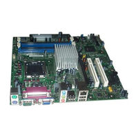
Category: Motherboard
|
Size: 0.82 MB
Table of Contents
Advertisement
Intel D915GAV Product Manual (80 pages)
Desktop Board
Brand: Intel
|
Category: Motherboard
|
Size: 1.72 MB
Table of Contents

Intel D915GAV Quick Reference (32 pages)
Brand: Intel
|
Category: Motherboard
|
Size: 2.38 MB
Table of Contents
Advertisement

() Intel D915GAV Product Manual (110 pages)
Simplified Chinese D915GAV Product Guide
Brand: Intel
|
Category: Motherboard
|
Size: 2.12 MB
Table of Contents
Advertisement