Sign In
Upload
Manuals
Brands
Emerson Manuals
Controller
Rosemount 5402
Emerson Rosemount 5402 Manuals
Manuals and User Guides for Emerson Rosemount 5402. We have
3
Emerson Rosemount 5402 manuals available for free PDF download: Reference Manual, Advanced User's Manual
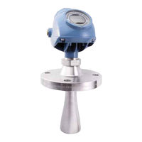
Emerson Rosemount 5402 Reference Manual (314 pages)
Superior Performance Two-Wire Non-Contacting Radar Level Transmitter
Brand:
Emerson
| Category:
Transmitter
| Size: 4.64 MB
Table of Contents
Table of Contents
5
Manual Overview
13
Service Support
15
Product Recycling/ Disposal
16
Safety Messages
16
Theory of Operation
19
Application Examples
20
System Architecture
22
Process Characteristics
24
Components of the Transmitter
26
Antenna Selection Guide/Measuring Range
27
Safety Messages
31
Installation Procedure
33
Mounting Considerations
34
Mounting Location
34
Special Considerations in Solids Applications
36
Mounting in Pipes
37
Installation Considerations
38
Nozzle Considerations
39
Nozzle Recommendations and Requirements
42
Service Space
44
Beamwidth
45
Vessel Characteristics
47
10Disturbing Objects
47
11Valves
47
Mounting
48
Cone Antenna Flange Connection
48
Process Seal Antenna
49
Rod Antenna Threaded Connection
50
Rod Antenna Flanged Connection
51
Tri-Clamp™ Tank Connection
52
Bracket Mounting on Wall
53
Bracket Mounting on Pipe
54
Safety Messages
55
Wiring and Power Supply Requirements
56
Cable/Conduit Entries
57
Conduit Electrical Connector Wiring (Using Minifast ® )
57
Grounding
58
Cable Selection
58
Hazardous Areas
59
External Circuit Breaker
59
Connecting the Transmitter
59
Hart
61
Power Requirements
61
Load Limitations
61
Non-Intrinsically Safe Power Supply
63
Intrinsically Safe Power Supply
64
Type N Approvals: Non-Sparking / Energy-Limited Power Supply
65
Transient Protection Terminal Block
66
Foundation
67
OUNDATION Fieldbus
67
Power Requirements
67
Fieldbus
67
Non-Intrinsically Safe Power Supply
69
Intrinsically Safe Power Supply
70
Type N Approvals: Non-Sparking / Energy-Limited Power Supply
71
HART to Modbus Converter (HMC)
72
1Connecting the Transmitter
72
2Connection Terminals
74
3RS-485 Bus
75
4Installation Cases
75
5External HART Devices (Slaves)
77
Establish HART Communication
78
1Connect to the MA/MB Terminals
78
2Connect to the HART Terminals
80
Optional Devices
81
1Tri-Loop™ HART to Analog Converter
81
2751 Field Signal Indicator
82
3Smart Wireless THUM ™ Adapter
83
Safety Messages
85
5Section 5: Basic Configuration/Start-Up
86
Overview
86
Basic Configuration Parameters
86
Configuration Tools
86
Basic Configuration Parameters
87
Measurement Units
87
Tank Geometry
87
Process Conditions
89
Volume Configuration
90
Analog Output (HART)
93
Level and Distance Calibration
94
Echo Tuning
95
Atc
96
Basic Configuration Using RRM
96
System Requirements
96
Help in RRM
97
Installing the RRM Software for HART Communication
97
Specifying the COM Port
99
To Set the COM Port Buffers
100
Specifying Measurement Units
100
Installing the RRM Software for FOUNDATION Fieldbus
100
Specifying Measurement Units
102
Using the Setup Functions
103
10Guided Setup
104
11Using the Setup Functions
112
Configuration Using a Field Communicator
113
Basic Configuration Using AMS Suite
117
Configuration Using Deltav
118
Advanced Configuration
123
Foundation
124
OUNDATION Fieldbus Overview
124
Assigning Device Tag and Node Address
125
Foundation Fieldbus Block Operation
125
Application Examples
127
1Radar Level Transmitter - Level Value
127
2Radar Level Transmitter - Level Value in Percent (%)
128
Tri-Loop™ HART to Analog Converter
129
HART Multidrop Configuration
130
Safety Messages
131
Viewing Measurement Data
132
Using the Display Panel
132
Specifying Display Panel Variables
132
Viewing Measurement Data in RRM
136
Viewing Measurement Data in AMS Suite and Deltav
137
LCD Display Error Messages
138
LED Error Messages
139
Safety Messages
141
Troubleshooting Overview
143
Service Overview
144
Analyzing the Measurement Signal
144
Surface Pulse Not Found
145
Registration of False Echoes
147
Using the Echo Curve Analyzer
149
Using the Echo Curve Analyzer with a Field Communicator
152
Analog Output Calibration
154
Logging Measurement Data
155
Backing up the Transmitter Configuration
156
Diagnostics
157
Configuration Report
159
Viewing Input and Holding Registers
160
Reset to Factory Settings
161
Surface Search
162
Using the Simulation Mode
163
Write Protecting a Transmitter
164
Diagnostic Messages
165
1Troubleshooting
165
2Device Status
165
3Errors
166
4Warnings
167
5Measurement Status
167
6Volume Calculation Status
169
7Analog Output Status
170
8Application Errors
171
Troubleshooting
175
1Resource Block
176
2Transducer Block
177
3Analog Input (AI) Function Block
177
Safety Messages
179
Overview
180
Applicable Models
180
Skill Level of Personnel
181
Functional Specifications
181
Installation
181
Configuration
183
Damping
183
Alarm and Saturation Levels
183
Amplitude Threshold
184
Write Protection
184
Site Acceptance
184
Operation and Maintenance
184
General
184
Inspection
185
References
186
Specifications
186
Failure Rate Data
186
Useful Lifetime
186
Spare Parts
186
Terms and Definitions
186
Functional Specifications
189
General
189
A.1 Functional Specifications
189
Ma HART (Output Option Code H)
190
Foundation™ Fieldbus (Output Option Code F)
193
RS-485 with Modbus Communication
195
(Output Option Code M)
195
Display and Configuration
197
Diagnostics
198
A.1.6 Diagnostics
198
Temperature and Pressure Limits
199
Performance Specifications
201
General
201
A.2 Performance Specifications
201
Measuring Range
202
A.2.2 Measuring Range
202
Beam Angle and Beam Width
203
Transition Zone and Near Zone
205
Environment
206
A.2.5 Environment
206
Physical Specifications
207
Material Selection
207
Housing and Closure
207
A.3 Physical Specifications
207
Engineered Solutions
208
Tank Connection and Antennas
208
A.3.3 Engineered Solutions
208
Dimensional Drawings and Mechanical Properties
212
Rosemount 5402 and 5401 with SST Cone Antenna
212
(Model Code: 2S-8S)
212
Rosemount 5402 and 5401 with Protective Plate Cone Antenna (Model Code: 2H-8H, 2M-8M, and 2N-8N)
213
Rosemount 5401 with Rod Antenna (Model Code: 1R-4R)
214
Rosemount 5402 with Process Seal Antenna
215
(Model Code: 2P-4P)
215
Bracket Mounting (Model Code: BR)
216
Process Connections
217
A.4.6 Process Connections
217
A.5 Ordering Information
218
Ordering Information
218
B.1 Safety Messages
229
Safety Messages
229
European Directive Information
231
FCC and ICC
231
Safety Instrumented Systems (SIS)
231
Hazardous Locations Certifications
232
North-American Certifications
232
Canadian Standards Association (CSA) Approvals
233
European Certifications
234
B.5.3 European Certifications
234
Iecex Approval
236
B.5.4 Iecex Approval
236
EAC Certifications
237
B.5.5 EAC Certifications
237
Brazilian Certifications
238
Chinese Certifications
238
B.5.6 Brazilian Certifications
238
Japanese Certifications
239
B.5.8 Japanese Certifications
239
Other Certifications
240
B.5.9 Other Certifications
240
B.5.10Canadian Registration Number (CRN)
241
Approval Drawings
242
B.6 Approval Drawings
242
Rev HA November
243
Tank Geometry
249
Distance Offset (G)
249
C.1 Tank Geometry
249
Minimum Level Offset (C)
250
Hold off Distance
250
Calibration Distance
250
Advanced Analog Output Settings
251
Advanced Transmitter Settings
251
Antenna Type
251
Empty Tank Handling
251
Full Tank Handling
253
Double Bounce
253
Surface Echo Tracking
254
Filter Settings
255
Advanced Functions in RRM
255
Empty Tank Handling
255
C.3.6 Filter Settings
255
Full Tank Handling
259
Double Bounce
260
C.4.3 Double Bounce
260
Surface Echo Tracking
261
Hold off Setting
262
Performing Proof Test
263
Field Communicator
263
Rrm
265
D.4 AMS Suite
267
AMS Suite
267
Overview
269
Definition
269
Channel Definitions
269
E.1 Overview
269
Parameters and Descriptions
270
Supported Units
275
Unit Codes
275
E.3 Supported Units
275
Diagnostics Device Errors
276
Overview
277
Register Access Transducer Block Parameters
277
F.1 Overview
277
Overview
281
Advanced Configuration Transducer Block Parameters
281
G.1 Overview
281
H.1 Overview
285
Plantweb® Alerts
290
Alarm Priority
293
H.2.2 Alarm Priority
293
Recommended Actions for Plantweb Alerts
294
Overview
285
Parameters and Descriptions
285
Simulation
300
Advertisement
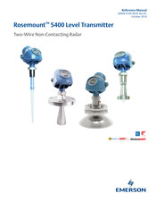
Emerson Rosemount 5402 Reference Manual (338 pages)
Level Transmitter, Two-Wire Non-Contacting Radar
Brand:
Emerson
| Category:
Transmitter
| Size: 32.56 MB
Table of Contents
Table of Contents
3
Using this Manual
15
Product Recycling/Disposal
16
Theory of Operation
17
Application Examples
18
System Architecture
20
Process Characteristics
22
Components of the Transmitter
24
Antenna Selection Guide/Measuring Range
25
Safety Messages
29
Installation Procedure
31
Mounting Considerations
32
Mounting Location
32
Special Considerations in Solids Applications
34
Mounting in Pipes
35
Condensation Conditions
36
Nozzle Considerations
37
Nozzle Recommendations and Requirements
41
Service Space
45
Beam Width
46
Vessel Characteristics
48
Disturbing Objects
48
Valves
48
Mounting
49
Cone Antenna with Flange Connection
49
Cone Antenna with Threaded Tank Connection
50
Cone Antenna with Threaded Tank Connection and Customer Supplied Flange
52
Process Seal Antenna with Flange
60
Parabolic Antenna with Flange
62
Parabolic Antenna with Welded Connection
64
Parabolic Antenna with Threaded Connection
71
Adjust Inclination of Parabolic Antenna
77
Rod Antenna with Threaded Connection
81
Rod Antenna with Flanged Connection
82
Tri Clamp Tank Connection
83
Bracket Mounting
84
Safety Messages
85
Wiring and Power Supply Requirements
87
Cable/Conduit Entries
87
Grounding
87
Cable Selection
88
Hazardous Areas
88
External Circuit Breaker
88
Connecting the Transmitter
89
HART ® Communication
92
Power Requirements
92
Load Limitations
92
Non-Intrinsically Safe Power Supply
94
Intrinsically Safe Power Supply
95
Type N Approvals: Non-Sparking/Energy-Limited Power Supply
96
Transient Protection Terminal Block
96
Foundation
97
OUNDATION Fieldbus
97
Power Requirements
97
Non-Intrinsically Safe Power Supply
99
Intrinsically Safe Power Supply
100
Type N Approvals: Non-Sparking/Energy-Limited Power Supply
101
HART to Modbus Converter (HMC)
102
Connecting the Transmitter
102
Connection Terminals
104
Bus
105
Installation Cases
105
External HART Devices (Slaves)
107
Establish HART Communication
108
Connect to the MA/MB Terminals
108
Connect to the HART Terminals
110
Optional Devices
111
1Tri-Loop™ HART to Analog Converter
111
Field Signal Indicator
111
Emerson ™ Wireless THUM ™ Adapter
112
Safety Messages
113
Overview
114
Basic Configuration Parameters
114
Configuration Tools
114
Basic Configuration Parameters
115
Measurement Units
115
Tank Geometry
115
Process Conditions
117
Volume Configuration
118
Analog Output (HART)
121
Level and Distance Calibration
122
Echo Tuning
123
Atc
124
Basic Configuration Using RRM
124
System Requirements
124
Help in RRM
125
Installing the RRM Software for HART Communication
125
Specifying the COM Port
126
Setting the COM Port Buffers
127
Specifying Measurement Units
127
Installing the RRM Software for FOUNDATION Fieldbus
127
Specifying Measurement Units
129
Using the Setup Functions
130
Guided Setup
131
Using the Setup Functions
142
Configuration Using a Field Communicator
143
Basic Configuration Using AMS Suite
147
Configuration Using Deltav
148
Advanced Configuration
153
Foundation
154
Assigning Device Tag and Node Address
155
FOUNDATION Fieldbus Block Operation
155
Application Examples
157
Radar Level Transmitter - Level Value
157
Radar Level Transmitter - Level Value in Percent (%)
158
Tri-Loop™ HART to Analog Converter
159
HART Multidrop Configuration
161
Safety Messages
163
Viewing Measurement Data
165
Using the Display Panel
165
Specifying Display Panel Variables
165
Viewing Measurement Data in RRM
168
Viewing Measurement Data in AMS Suite and Deltav
170
LCD Display Error Messages
171
LED Error Messages
172
Safety Messages
173
Troubleshooting Overview
175
Service Overview
176
Analyzing the Measurement Signal
176
Surface Pulse Not Found
177
Registration of False Echoes
178
Using the Echo Curve Analyzer
180
Using the Echo Curve Analyzer with a Field Communicator
183
Analog Output Calibration
185
Logging Measurement Data
186
Backing up the Transmitter Configuration
187
Diagnostics
188
Configuration Report
189
Viewing Input and Holding Registers
190
Reset to Factory Settings
191
Surface Search
192
Using the Simulation Mode
193
Write Protecting a Transmitter
194
Diagnostic Messages
195
Troubleshooting
195
Device Status
195
Errors
196
Warnings
197
Measurement Status
197
Volume Calculation Status
199
Analog Output Status
200
Application Errors
201
Troubleshooting
205
Resource Block
206
Transducer Block
207
Analog Input (AI) Function Block
208
Service Support
210
Safety Messages
211
Overview
212
Applicable Models
212
Skill Level of Personnel
212
Functional Specifications
213
Installation
213
Configuration
215
Damping
215
Alarm and Saturation Levels
215
Amplitude Threshold
216
Write Protection
216
Site Acceptance
216
Operation and Maintenance
216
General
216
Inspection
217
References
218
Specifications
218
Failure Rate Data
218
Useful Lifetime
218
Spare Parts
218
Terms and Definitions
218
Aappendix A: Specifications and Reference Data
219
Functional Specifications
219
General
219
4-20 Ma HART® (Output Option Code H)
219
FOUNDATION ™ Fieldbus (Output Option Code F)
221
Rosemount 2410 Tank Hub Connectivity (Output Option Code U)
222
With Modbus Communication (Output Option Code M)
222
Display and Configuration
223
Diagnostics
224
Temperature Limits
224
Process Temperature and Pressure
225
Performance Specifications
226
General
226
Measuring Range
226
Solids Applications
229
Environment
230
Physical Specifications
230
Material Selection
230
Housing and Closure
230
Engineered Solutions
231
Tank Connection and Antennas
231
Dimensional Drawings and Mechanical Properties
233
Process Connections
239
Ordering Information
241
European Directive Information
253
Ordinary Location Certification
253
Fcc
253
Radio Equipment Directive (RED)
254
Installing Equipment in North America
254
Usa
254
Canada
255
Europe
256
International
258
Brazil
259
China
260
Technical Regulations Customs Union (EAC)
261
Japan
261
India
261
Ukraine
261
Uzbekistan
261
Republic of Korea
262
Combinations
262
Additional Certifications
262
Pattern Approval
262
Conduit Plugs and Adapters
263
Approval Drawings
263
Safety Messages
269
Tank Geometry
270
Distance Offset (G)
270
Minimum Level Offset (C)
270
Hold off Distance
271
Calibration Distance
271
Advanced Analog Output Settings
271
Advanced Transmitter Settings
272
Antenna Type
272
Empty Tank Handling
272
Full Tank Handling
273
Double Bounce
273
Surface Echo Tracking
274
Filter Settings
275
Advanced Functions in RRM
276
Empty Tank Handling
276
Full Tank Handling
279
Double Bounce
280
Surface Echo Tracking
281
Hold off Setting
282
Signal Quality Metrics (SQM)
283
Available Diagnostics Measurements
283
How to Verify if Signal Quality Metrics Is Supported
284
View Signal Quality Metrics Values in RRM
285
Performing Proof Test
287
Field Communicator
287
Rrm
289
AMS Suite
291
Overview
293
Definition
293
Channel Definitions
293
Supported Units
301
Unit Codes
301
Diagnostics Device Errors
302
Overview
311
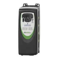
Emerson Rosemount 5402 Advanced User's Manual (201 pages)
Commander SK series AC variable speed drive for 3 phase induction motors from 0.25kW to 110kW, 0.33hp to 150hp
Brand:
Emerson
| Category:
Controller
| Size: 6.36 MB
Table of Contents
Drive Software Version
2
General Information
2
Table of Contents
3
2 Parameter X.00
5
Eur/Usa Parameter Set Differences
5
Saving Parameters
5
Loading Default Parameters
5
3 Parameter Description Format
6
Software Variable Maximum Term Definitions
6
Parameter Information
7
Key to Parameter Codes
8
Coding
8
Sources and Destinations
9
Sample/Update Times
9
4 Keypad and Display
10
Programming Keys
10
Control Keys
10
Selecting and Changing Parameters
10
5 Serial Communications
12
CT Comms Cable
12
EIA232 to EIA485 Communications
12
Multi-Drop Converters
13
Isolation of the Communications Port
14
Serial Communications Connections
14
Terminating Resistors
14
CT Modbus RTU Specification
16
Data Consistency
17
MODBUS Registers
17
Slave Address
17
Data Encoding
18
Function Codes
18
Communications Timeouts
20
Extended Data Types
20
Exceptions
22
Crc
23
7 PLC Ladder Programming
24
System Requirements
24
Menu 0 Logic Diagram
32
10 Advanced Parameter Descriptions
33
Overview
33
Menu 1: Speed Reference Selection, Limits and Filters
34
Frequency Reference Selected
38
Pre-Skip Filter Reference
38
Reference Offset
38
Maximum Set Speed
38
Minimum Set Speed
39
Reference Offset Select
39
Allow Negative References
39
Reference Enabled Indicator
40
Preset Speed Selector
41
Keypad Reference
42
Precision Reference Coarse
42
Precision Reference Fine
42
Precision Reference Update Disable
42
Preset Speed
43
Skip Reference
43
Skip Reference Band
43
Reference in Rejection Zone
43
Analog Reference
44
Percentage Trim
44
Reference Selected Indicator
44
Preset Select Bit
44
Preset Reference Selected Indicator
45
Power-Up Keypad Reference
45
Menu 2: Ramps
46
Post Ramp Reference
49
Unused Parameter
49
Ramp Mode Select
49
S Ramp Enable
50
S Ramp Acceleration Limit
50
Standard Ramp Voltage
51
Acceleration Rate Selector
51
Acceleration Rate
52
Jog Acceleration Rate
52
Deceleration Rate Selector
52
Deceleration Rate
53
Jog Deceleration Rate
53
Acceleration Selected Indicator
53
Deceleration Selected Indicator
54
Acceleration Select Bit
54
Deceleration Select Bit
54
Ramp Rate Units
54
Menu 3: Speed Sensing Thresholds and Frequency Input and Output
55
Frequency Input and Output
58
Zero Speed Threshold/At Speed Window
58
Frequency Output or PWM Output Scaling
58
Maximum Output Frequency or Maximum PWM Output Frequency
58
Hard Frequency Reference
59
Hard Frequency Reference Selector
59
Position Counter Reset
59
Position Scaling Numerator
59
Position Scaling Denominator
60
Maximum Reference Frequency
60
Frequency Reference Scaling
60
Frequency Reference
60
Menu 4: Current Control
61
Current Magnitude (Motor Current)
64
Motor Active Current
65
Current Demand
65
Symmetrical Current Limit
65
Torque Reference
66
Torque Mode Selector
66
Current Limit Operation
67
Torque Control
67
Mains Loss and Controlled Standard Ramp
67
Motor Thermal Time Constant
68
Motor Thermal Protection Mode
68
Reactive Current (Motor Magnetising Current)
70
Overriding Current Limit
70
Motor Overload Accumulator
70
Percentage Load/Load Display Units
70
User Current Maximum Scaling
71
Low Speed Thermal Protection Mode
71
Percentage Torque
71
Reduce Internal Current Loop Response
71
Menu 5: Motor Control
72
Motor Frequency/Motor Voltage
74
Output Power
74
Motor Speed
74
DC Bus Voltage
74
Motor Rated Frequency
75
Motor Rated Current
75
Motor Rated Full Load Rpm
75
Open-Loop Vector Mode
76
Fixed Boost Mode
76
Square Law Mode
76
Motor Rated Power Factor
77
Number of Motor Poles
77
Autotune
77
Parameters Used in the Vector Control Algorithm
78
Dynamic V to F Select
78
Stator Resistance and Voltage Offset Measured on each Run Signal
79
No Measurements
79
Square Law Characteristic
79
Stator Resistance
80
Maximum Switching Frequency
80
High Stability Space Vector Modulation
80
Voltage Offset
81
Transient Inductance
81
Enable Slip Compensation
82
Speed Display Units
82
Disable Auto-Switching Frequency Change
82
Actual Switching Frequency
83
Security Unlock
83
Menu 6: Drive Sequencer and Clock
84
Stop Mode Select
87
Mains Loss Mode
88
Start/Stop Logic Select
89
Injection Braking Level
90
Injection Braking Time
90
Catch a Spinning Motor Select
91
Low DC Bus Operation
91
Remote LED Keypad Function Key Status
92
Enable Stop Key
92
Function Key Mode
93
Disable Auto-Reset on Enable
93
Drive Enable
94
Electricity Cost Per Kwh
94
Reset Energy Meter
94
Run Time Log
94
Energy Meter
95
Running Cost
95
Hardware Enable
95
Sequencing Bit
95
Sequencing Bit: Jog Reverse
96
Sequencing Bit: /Stop
96
Enable Sequencer Latching
99
Control Word
99
Control Word Enable
99
Force Cooling Fan to Run at Full Speed
100
Menu 7: Analog Inputs and Outputs
101
Analog Input 1 Level (Terminal T2)
103
Analog Input 2 Level (Terminal T4)
103
Heatsink Temperature
103
Power Circuit Temperature 2
103
Analog Input 1 Mode
104
Analog Input 1 Scaling
105
Analog Input 1 Invert
105
Analog Input 1 Destination
105
Analog Input 2 Mode (Terminal T4)
106
Analog Input 2 Scaling
106
Analog Input 2 Invert/Analog Input 2 Destination
106
Analog Output Source
106
Analog Output Scaling
107
Current Loop Loss Indicator
107
Analog Input 1 Offset
107
Analog Output Control (Terminal B1)
107
IGBT Junction Temperature
108
Drive Thermal Protection Accumulator
108
Power Circuit Temperature 3
108
Menu 8: Digital Inputs and Outputs
109
Terminal B4-B7 Digital Input State
114
Status Relay State (Terminals T5 and T6)
114
Terminal B4-B6 Digital Input Invert
114
Terminal B7 Digital Input Invert
114
Status Relay Invert
115
Digital I/O Read Word
115
Terminal B4-B7 Digital Input Destination
115
Status Relay Source
116
Terminal B3 Mode Select
116
Terminal B7 Mode Select
116
Digital Output Control (Terminal B3)
117
Menu 9: Programmable Logic, Motorized Pot and Binary Sum
118
Logic Function 1/2 Output
121
Motorized Pot Output
121
Logic Function 1 Source 1
121
Logic Function 1 Source 2
121
Logic Function 1 Source 2 Invert
122
Logic Function 1 Output Invert
122
Logic Function 1 Delay
122
Logic Function 1 Destination
122
Logic Function 2 Source 1/Logic Function 2 Source 1 Invert
123
Logic Function 2 Source 2
123
Logic Function 2 Source 2 Invert
123
Logic Function 2 Output Invert/Logic Function 2 Delay
123
Logic Function 2 Destination
124
Motorized Pot Mode
124
Motorized Pot Bipolar Select
124
Motorized Pot Rate/Motorized Pot Scale Factor
125
Motorized Pot Destination
125
Motorized Pot Up/Down/Reset
125
Binary Sum One’s Input/Two’s Input/Four’s Input
125
Binary Sum Output
126
Binary Sum Offset
126
Menu 10: Status Logic and Diagnostic Information
128
Drive Ok
129
Drive Active
129
Zero Speed
129
Running at or below Minimum Speed
129
Drive Output Is at Current Limit
130
Regenerating
130
Dynamic Brake Active
130
Direction Commanded
130
Overload Alarm
131
Drive Temperature Alarm
131
General Drive Alarm
131
Last Trip
131
Trip Indications
132
Under Voltage Trip and Restart Levels
133
HF Trips
134
Alarm Warnings
134
Display Indications
134
Full Power Braking Time
135
Full Power Braking Period
135
External Trip/Drive Reset
136
No. of Auto-Reset Attempts
136
Auto-Reset Delay
136
Hold ‘Drive Ok’ until Last Attempt
136
Action on Trip Detection
137
User Trip
137
Braking Energy Overload Accumulator
137
Status Word
137
Menu 11: General Drive Set-Up
138
Pr 61-70 Set-Up
139
Customer Defined Scaling
139
Parameter Displayed at Power-Up
139
Serial Comms Address
139
Modbus RTU / User Serial Mode
140
Serial Comms Baud Rate
140
Silent Period Extension
140
Drive Configuration
140
Parameter Changes When Drive Configuration Is Changed
141
PID Logic Diagram
146
Software Version
146
User Security Code
147
Maximum Heavy Duty Drive Current Rating
147
Drive Voltage Rating
147
Software Sub-Version/Dsp Software Version
147
Status Mode Timeout
148
Parameter Copying
148
Different Drive Ratings
148
Load Defaults
149
Security Status
149
Select Motor 2 Parameters
150
Defaults Previously Loaded
150
PLC Ladder Program Status
150
PLC Ladder Program Enable
150
PLC Ladder Program Maximum Scan Time
151
Menu 12: Programmable Threshold and Variable Selector
152
Threshold Detector 1/2 Output
156
Threshold Detector 1 Hysteresis
156
Threshold Detector 1 Output Invert
156
Threshold Detector 1 Destination
156
Variable Selector 1 Source 1/2
157
Variable Selector 1 Mode
157
Variable Selector 1 Destination
157
Variable Selector 1 Output
157
Variable Selector 1 Source 1/2 Scaling
158
Variable Selector 1 Control
158
Threshold Detector 2 Source
158
Threshold Detector 2 Level/Hysteresis
158
Threshold Detector 2 Output Invert
159
Threshold Detector 2 Destination
159
Variable Selector 2 Source 1/2
159
Variable Selector 2 Mode
159
Variable Selector 2 Destination
160
Variable Selector 2 Output
160
Variable Selector 2 Source 1/2 Scaling
160
Variable Selector 2 Control
160
Brake Control Function
161
Brake Release Indicator
161
Brake Controller Enable
161
Brake Function Diagram
162
Brake Sequence
162
Brake Release Current Threshold
163
Brake Apply Current Threshold
163
Brake Release Frequency/Brake Apply Frequency
163
Pre-Brake Release Delay
163
Post-Brake Release Delay
164
Menu 14: PID Controller
165
PID Output
167
PID Reference Source
167
PID Reference Source Invert
167
PID Reference Slew Rate Limit
167
PID Enable
168
Optional PID Enable Source
168
PID Proportional Gain
168
PID Integral Gain/Pid Derivative Gain/Pid High Limit
168
PID Low Limit/Pid Scaling/Pid Output Destination
169
PID Hold Integrator
169
Select Symmetrical Limit on PID
169
PID Main Reference
169
PID Reference
170
PID Feedback
170
PID Error
170
Solutions Module ID
171
Menu 15: Solutions Module Set-Up
171
SM-I/O Lite and SM-I/O Timer Solutions Module
172
Solutions Module Identification Code
177
Solutions Module Software Version
177
Terminal T5-7 Digital Input 1-3 State
178
Relay 1 State (Terminals T21 and T23)
178
Terminal T5-7 Digital Input 1-3 Invert
178
Relay 1 Invert (Terminals T21 and T23)
178
Real Time Clock Daylight Saving Mode
179
Terminal T5-7 Digital Input 1-3 Destination
179
Terminal T21/T23 Relay 1 Source
179
Real Time Clock Update Mode / Minutes/Seconds / Days/Hours
180
Real Time Clock Month/Date
180
Real Time Clock Years
180
Analog Input 1 Mode (Terminal T2)
180
Analog Output 1 Mode (Terminal T3)
181
Analog Input 1 Scaling (Terminal T2)
181
Analog Input 1 Invert (Terminal T2)
181
Analog Input 1 Destination (Terminal T2)
182
Analog Output 1 Source (Terminal T3)
182
Analog Output 1 Scaling (Terminal T3)
182
Solutions Module Error Status
182
Solutions Module Software Sub-Version
183
Drive Encoder Lines Per Revolution
183
Drive Encoder Revolution Counter/Drive Encoder Position
183
Drive Encoder Speed Feedback/Maximum Drive Encoder Reference
183
Drive Encoder Reference Level
184
Drive Encoder Reference Scaling
184
Drive Encoder Reference Destination
184
Encoder Reset
184
Menu 18: Application Menu 1
185
Application Menu 1 Power-Down Saved Integer
186
Application Menu 1 Read-Only Integer
186
Application Menu 1 Read-Write Integer
186
Application Menu 1 Read-Write Bit
186
Application Menu 2 Read-Write Long Integer
187
Menu 20: Application Menu 2
187
Menu 21: Second Motor Map
188
Motor 2 Maximum Set Speed
189
Motor 2 Minimum Set Speed
189
Motor 2 Reference Selector
189
Motor 2 Acceleration Rate
190
Motor 2 Deceleration Rate
190
Motor 2 Motor Rated Frequency
191
Motor 2 Motor Rated Current
191
Motor 2 Motor Rated Full Load Rpm
191
Motor 2 Motor Rated Voltage
192
Motor 2 Motor Rated Power Factor
193
Motor 2 Number of Motor Poles
193
Motor 2 Stator Resistance
194
Motor 2 Voltage Offset
194
Motor 2 Transient Inductance
194
Motor 2 Active
195
Motor 2 Thermal Time Constant
195
Motor 2 Symmetrical Current Limit
195
Index
196
Advertisement
Advertisement
Related Products
Emerson Rosemount 5401
Emerson TESCOM 54-2000 Series
Emerson TESCOM 54-2200 Series
Emerson TESCOM 54-2800 Series
Emerson TESCOM 54-2100 Series
Emerson TESCOM 54-2300 Series
Emerson TESCOM 54-2700 Series
Emerson TESCOM 54-3500 Series
Emerson 5601
Emerson Rosemount 3490 Series
Emerson Categories
Controller
Control Unit
Transmitter
Measuring Instruments
Fan
More Emerson Manuals
Login
Sign In
OR
Sign in with Facebook
Sign in with Google
Upload manual
Upload from disk
Upload from URL