Sign In
Upload
Manuals
Brands
Delta Manuals
Servo Drives
ASDA Series
Delta ASDA Series Manuals
Manuals and User Guides for Delta ASDA Series. We have
1
Delta ASDA Series manual available for free PDF download: Application Notes
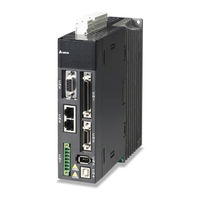
Delta ASDA Series Application Notes (274 pages)
Brand:
Delta
| Category:
Servo Drives
| Size: 10.25 MB
Table of Contents
Table of Contents
5
System Information
8
What Is System Parameter and How Is It Used
8
Mapping Parameter
12
Data Array
16
Introduction of ASDA-A2 PR Function
16
Shared Setting List for PR
19
Introduction of PR Homing
20
Reference to Limit
20
Reference to Z Pulse
23
Reference to the Falling-Edge Signal on Home Sensor
24
Reference to Current Position
26
PR Speed Command
28
PR Position Command
29
Jump Command
31
PR Write-In Command
31
PR Triggering Methods
32
Trigger by DI.CTRG / POS0 ~ POS5 / STOP
32
Parameter P5-07
32
DI.shom
33
Event Trigger
33
Motion Control
35
Others CAPTURE Completed / COMPARE Completed / E-CAM
35
Disengaged
35
Monitoring Variables Related to PR
35
Overlap of Commands
40
Interrupt of Command
41
Presentation of PR
45
How Is PR Arranged
48
PR Setting Examples
50
Introduction of E-Cam Operation
65
Introduction of E-Cam
65
Introduction of E-Cam
66
Source of the Master Axis
69
The Clutch
71
Settings for Engaging E-Cam
71
The E-Gear of the Master Axis
77
E-Cam Curve
78
Create an E-Cam Curve by Software
80
Using Macro to Create an E-Cam Curve
96
E-Gear Ratio and Scaling of E-Cam Curve
104
E-Cam Setting Example
106
Creating an E-Cam Curve
106
Relevant Parameter Settings and Enabling E-Cam Function
108
Simultaneously Using E-Cam Function and PR Command
110
Troubleshooting When E-Cam Is Not Working Properly
112
Application Examples
113
How to Use Capture Function to Create E-Cam Curves
116
Description
116
About the System and System Configuration
116
Creating an E-Cam Curve
116
Settings for the Route of Master Axis (Rectangle Carrier)
117
Settings for the Route of Slave Axis (Round Compression Axis)
118
Servo System Structure and Configuration
118
System Structure
119
Wiring
119
Parameter Settings for Master Axis (Rectangle Carrier)
120
Parameter Settings for Slave Axis (Round Compression Axis)
122
Settings for Capture Function
128
E-Cam Parameter Settings
130
Test the System
132
Application to Winding Machine
135
Description
135
System Theorem and Scheme
135
Master Axis
135
Camshaft
136
Servo System Setting
136
The Design of Tape
136
The Meaning of E-Cam Curve
138
Example
139
PR Programming and Execution
142
System Adjustment
146
The Design of E-Cam Curve
148
Application to Labeling Machine
151
Description
151
System Plan
151
Camshaft Axis - Label Feeding Axis
152
Label Positioning Sensor
152
Labeling Start Sensor
152
Master Axis - Axis of Conveyor
152
Setting of Servo System
152
Camshaft Is Enabled and Starts to Label
152
Camshaft Is Disabled and Label Positioning
154
PR Program and Execution
156
Structure of E-Cam Curve
158
E-Cam Curve Creation
160
Analysis of E-Cam Curve
167
Printing Machine Application with Synchronization of Multiple Axes
169
Description
169
System Operation and Configuration
169
How to Configure Your System
169
Analysis of System Operation
170
Servo System Setting
170
PR Procedure and E-Cam Curve
170
Simulative Operation
172
Application to Gantry
176
Introduction
176
How Gantry Works and the System Structure
176
How Does Gantry Work
176
Positioning and Homing of Gantry
177
Motion Following
179
Servo System Settings
180
Wiring
180
Sequential Logic Control of Positioning and Homing
183
Steps for Adjusting the Servo When Using Gantry Control
189
Application Example of Packing Machine
195
Description
195
System Plan
195
Camshaft (Flying Shear)
196
Master Axis (Film Feeding Axis)
196
Camshaft (Chain Conveyor)
197
Servo System Setting
197
System Configuration
197
Function Introduction
198
Design of E-Cam Curve
204
Application of Precision Positioning Via Mark Reading
207
Description
207
DI Setting
207
Setting of Servo System
207
System Theorem and Setting
207
System Configuration
208
Motion Command and PR Program
209
Application Example of Packing Machine with Phase Alignment Function
213
Instruction
213
System Configuration
213
Configuration
214
Servo System Setup
214
Features
216
Design of E-Cam Curve
235
Application Techniques
239
DO Output with Fixed Distance
240
Description
240
System Configuration
240
Servo System Setting
241
How to Use E-Cam Function to Compensate Tolerances on Lead Screw
246
Description
246
How Does the System Work
246
Inconsistency between Command and Machine Position Caused by
246
Tolerances on Lead Screw
246
Servo System Configuration
247
The Conversion of Command and Compensation from Servo Drive
247
Measurement and Measuring Result
249
Using E-Cam on ASDA-A2 for Compensation
251
PT Command Transferred from Analog Voltage
255
Description
255
System Configuration
255
Servo System Setting
256
Wiring
256
Operation Steps
257
Speed Change During the Execution of PR Position Command
260
Speed Change During Execution of PR Position Command
260
Description
260
How Does System Work
260
Servo System Setting
261
PR Program Setting
261
Tips for Applying PR
261
Macro for E-Cam Application
264
Macro C
264
Macro D
265
Macro 10
268
Advertisement
Advertisement
Related Products
Delta ASD-A2R-0121 Series
Delta ASDA-B2-F Series
Delta ASD-A2-1021 Series
Delta ASD-A2-0221 Series
Delta ASD-A2-7523 Series
Delta ASD-A2-4543 Series
Delta ASD-A2-5543 Series
Delta ASD-A2-0721-E
Delta ASDA-A3 Series
Delta ASD-A3-0221
Delta Categories
Plumbing Product
Kitchen & Bath Fixtures
Bathroom Fixtures
Saw
Power Supply
More Delta Manuals
Login
Sign In
OR
Sign in with Facebook
Sign in with Google
Upload manual
Upload from disk
Upload from URL