Sign In
Upload
Manuals
Brands
Carrier Manuals
Furnace
59SC5B
Carrier 59SC5B Manuals
Manuals and User Guides for Carrier 59SC5B. We have
2
Carrier 59SC5B manuals available for free PDF download: Installation, Start-Up, Operating And Service And Maintenance Instructions, Product Data
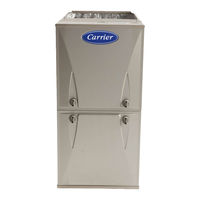
Carrier 59SC5B Installation, Start-Up, Operating And Service And Maintenance Instructions (89 pages)
Single Stage, 4-Way Multipoise, 35-in. (889 mm) Condensing Gas Furnace
Brand:
Carrier
| Category:
Furnace
| Size: 11.62 MB
Table of Contents
Table of Contents
1
Safety Precautions
3
Safety Considerations
3
Freeze Protection and Return Air Temperature
4
Introduction
4
Loose Parts Bag
4
Minimum Clearances to Combustible Materials
4
Accessories
5
Codes and Standards
5
Electrostatic Discharge (Esd) Precautions
5
Dimensional Drawing
6
Location
7
General
7
Prohibited Installations
8
Location Relative to Cooling Equipment
8
Installation in a Garage
8
Multipoise Orientations
8
Ventilated Combustion Air Applications
9
Outdoor Combustion Air Method
9
Air for Combustion and Ventilation
9
Indoor Combustion Aire NFPA and AGA
10
Standard Method
10
Combination of Indoor and Outdoor Air
10
Air for Combustion, Ventilation, and Dilution from Indoors
11
Air for Combustion, Ventilation, and Dilution for Outdoors
11
Min Free Area Required for each Combustion Air Opening
11
Min Space Volumes for 100% Combustion, Ventilation and Dilution Air
11
Minimum Free Area Required
11
Minimum Space Volumes
11
Upflow Orientation
12
Downflow Orientation
12
Horizontal Orientation
12
Condensate Trap
12
Upflow Trap Configuration
13
Downflow Trap Configuration
14
Horizontal Right Trap Configuration
15
Horizontal Left Configuration
16
For Left Side Condensate Drain Connection
17
Condensate Drain Connection
17
For Right Side Condensate Drain
17
Upflow/Downflow Orientation
17
Modify Rubber Drain Elbow
18
Formed Rubber Drain Grommet
18
Drain Trap Connection and Routing
19
Knockout Removal
19
Example of Field Drain Attachment
20
Upflow Installation
21
Supply Air Connections
21
Leveling Legs
22
Bottom Return Air Inlet
22
Side Return Air Inlet
22
Downflow Installation
22
Horizontal Installation
23
Return Air Connections
23
Platform Furnace Support
23
Suspended Furnace Support
23
Upflow Return Air Configurations and Restrictions
24
Downflow Return Air Configurations and Restrictions
24
Horizontal Return Air Configurations and Restrictions
24
Working Platform for Attic Installation
25
Suspended Furnace Installation
25
Removing Bottom Closure Panel
26
Filter Arrangement
26
Filter and Return Duct Sizing
27
Filter Media Pressure Drop (Clean) Versus Airflow
27
Filter Media Pressure Drop Versus Face Velocity
28
Air Filter Selection and Duct Sizing
28
Air Filter Located in Filter Cabinet
28
Media Filter
29
Installation on Combustible Flooring
30
Opening Dimensions
30
Air Ducts
30
Ductwork Acoustical Treatment
31
Return Duct Sizing
31
General Requirements
31
Air Delivery
32
Gas Pipe Grommet
33
Gas Piping
33
Gas Entry
34
Alternate Gas and Electric Entry
34
Electrical Connections
34
Maximum Capacity of Pipe
34
Installing J-Box
35
External Electrical Box on Furnace Casing
35
J-Box Installation
35
115 V Wiring
35
Top Panel -Mounted External Electrical Box
36
Power Cord Installation in Furnace J- Box
36
BX Cable Installation in Furnace J- Box
36
Field-Supplied External Electrical Box on Furnace Casing
36
24 -V Wiring
37
Alternate Power Supplies
37
Typical Single- Stage Wiring Diagram
37
Example of Single Stage Furnace Control
38
Electrical Data
38
Thermostat Wiring Diagrams
39
Notes for Thermostat Wiring Diagrams
39
Special Venting Requirements for Installations in Canada
39
Venting
39
Venting Systems
41
Ventilated Combustion Air Systems
41
Non-Direct Vent System
41
Vent Termination Kit for Direct Vent (2- -Pipe) System
41
Locating the Vent Termination
42
Ventilated Combustion Air
42
Size the Vent and Combustion Air Pipes
43
Non-Direct Vent / 1-Pipe System
43
Sample Inlet Air Pipe Connection for Polypropylene Venting Systems
43
Recommended Combustion Air Inlet Moisture Trap
44
Combustion Air and Vent Pipe Diameter Transition Location
44
Combustion Air and Vent Piping Insulation Guidelines
45
Configure the Furnace
46
Install the Vent and Combustion Air Pipes
46
Near Furnace Vent Connections
46
Installing the Vent Pipe Adapter and Combustion Air Pipe Adapter
47
Vent Coupling and Adapter with Gaskets
47
Inducer Vent Elbow
48
Hanger Spacing
48
Concentric Vent
49
Roof Terminations
49
Installing the Vent Termination
49
Optional Installation of the Vent Pipe
49
Sidewall Terminations Concentric Vent
50
Inducer Outlet Restrictor
50
Approved Combustion-Air and Vent Pipe, Fitting and Cement Materials
51
Maximum Allowable Exposed Vent Length in Unconditioned Space
52
Maximum Equivalent Vent Length
53
Deductions from Maximum Equivalent Vent Length
53
Venting System Length Calculations
54
Maximum Equivalent Vent Length
54
Inside Corner Terminations
55
Downflow Configurations
56
Upflow Configurations
56
Horizontal Left
57
Horizontal Right
57
Notes for Venting Options
58
Optional Vent Pipe Flush with Adaptor
58
Combustion Air Pipe Attachment
58
Direct Vent Termination Clearance
59
Ventilated Combustion Air and Non-Direct Vent Termination Clearance
60
Combustion Air and Vent Pipe Termination for Direct Vent System
61
Vent Pipe Termination for Non-Direct and Ventilated Air System
61
Alberta and Saskatchewan Vent Termination
62
Vent Terminations for Ventilated Combustion Air
63
Prime Condensate Trap with Water
64
Start- -Up, Adjustment, and Safety Check
64
Purge Gas Lines
65
Adjustments
65
Priming Condensate Trap
65
Orifice Hole
65
Orifice Size and Manifold Pressure for Gas Input Rate
67
Orifice Size and Manifold Pressure
69
Check Inlet Gas Pressure
70
Gas Valves
70
Burner Flame
71
Adjust Temperature Rise
71
Adjust Manifold Pressure
71
Adjust Blower off Delay
72
Adjust Cooling Airflow
72
Adjust Thermostat Heat Anticipator
72
Blower off Delay Jumper Positions
72
Check Safety Controls
73
Altitude Derate Multiplier for U.S.A.
73
Service
74
Component Test
74
Gas Rate
75
Retrieving Stored Fault Codes
76
Troubleshooting
76
Electrical Controls and Wiring
76
Service and Maintenance Procedures
76
Component Self-Test
77
Checklist
77
Cleaning And/Or Replacing Air Filter
78
Blower Motor and Wheel Maintenance
78
Blower Assembly
79
Cleaning Burners and Flame Sensor
80
Burner Assembly
80
Igniter Position - Top View
81
Cleaning Condensate Drain and Trap
81
Flushing Collector Box and Drainage System
81
Servicing Hot Surface Igniter
81
Cleaning Heat Exchangers
82
To Re-Install Condensate Drain and Trap
82
Checking Heat Pad Operation
82
Cleaning Heat Exchanger Cell
82
Winterization
83
Secondary Heat Exchangers
83
Sequence of Operation
84
Troubleshooting Guide
85
Wiring Diagram
87
Parts Replacement
88
Advertisement
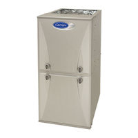
Carrier 59SC5B Product Data (19 pages)
95 Single-Stage, 4-Way Multipoise, Condensing Gas Furnace
Brand:
Carrier
| Category:
Furnace
| Size: 3.22 MB
Table of Contents
Features and Benefits
2
Model Number Nomenclature
3
Furnace Components
3
Specifications
4
Dimensional Drawing
10
Maximum Allowable Exposed Vent Length
11
Venting System Length Calculations
14
Return Air Temperature
15
Minimum Clearances to Combustible Materials
15
Typical Wiring Schematic
16
Guide Specifications
17
Advertisement
Related Products
Carrier Comfort 59SC5B026E14-10
Carrier Comfort 59SC5B040E14-10
Carrier Comfort 59SC5B040E17-12
Carrier Comfort 59SC5B060E14-12
Carrier Comfort 59SC5B060E17-14
Carrier Comfort 59SC5B080E17-16
Carrier Comfort 59SC5B080E21-20
Carrier Comfort 59SC5B100E21-20
Carrier Comfort 59SC5B100E21-22
Carrier Comfort 59SC5B120E24-22
Carrier Categories
Air Conditioner
Heat Pump
Furnace
Thermostat
Chiller
More Carrier Manuals
Login
Sign In
OR
Sign in with Facebook
Sign in with Google
Upload manual
Upload from disk
Upload from URL