Sign In
Upload
Manuals
Brands
Bosch Manuals
Measuring Instruments
Intellic EFAS-4.10
Bosch Intellic EFAS-4.10 Manuals
Manuals and User Guides for Bosch Intellic EFAS-4.10. We have
1
Bosch Intellic EFAS-4.10 manual available for free PDF download: Workshop Manual
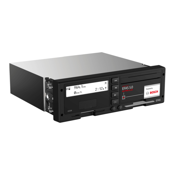
Bosch Intellic EFAS-4.10 Workshop Manual (115 pages)
Brand:
Bosch
| Category:
Measuring Instruments
| Size: 2.51 MB
Table of Contents
Table of Contents
7
Chapter 1 Introduction
11
Target Group
11
Symbols
11
Chapter 2 Legal Requirements
12
European Union Regulations
12
Regulation (EU) No. 165/2014
12
Regulation (EU) No. 2016/799
12
Regulation (EU) No. 2018/502
12
Regulation (EC) No. 561/ 2006
12
Directive 2002/15/EC
12
Directive 2014/30/EU
12
AETR Agreement
12
National Regulations
12
Chapter 3 General Information on Smart Recording Equipment
13
General Upgrading to Smart Recording Equipment According to Regulation (EU) no 2016/799
13
Exceptions from the Obligatory Use of Recording Equipment
13
Smart Recording Equipment
14
Provisions for Drivers and Employers
14
Description of the Tachograph Smart-Cards
14
Types of Tachograph Smart-Cards
15
Handling the Tachograph Smart-Cards
15
Viewing, Printing and Storing the Recorded Data
16
Viewing the Data
16
Handling the Printouts
16
Data Download
16
Handling the Data Readouts
16
Chapter 4 Control Elements and Displays
17
The EFAS Smart Tachograph
17
Keys
17
Figure 1 - Keys
17
Card Readers
18
Figure 2 - Card Readers
18
Display
19
Warning Light and Acoustic Signals
19
Figure 3 - Alphanumeric Display
19
Figure 4 - Red Warning Lights to Display the Operational Status
19
Table 1 - Warning Light and Acoustic Signals
19
Printer Paper Container
20
Service Port
20
Figure 5 - Printer Paper Container
20
Figure 6 - Service Port
20
Working with Menus
21
Using the Tachograph Smart-Cards
21
Table 2 - Pin Assignment of the Service Port
21
Card Combinations and Their Effect on the Operating Mode
22
Figure 7 - Smart-Card Access Locked While Traveling
22
Table 3 - Operating Modes - Symbols
22
Table 4 - Operating Modes from Tachograph Smart-Cards
22
Chapter 5 General Instructions Prior to Installation
23
Preparations for Installation in the Vehicle
23
Receipt of Device
23
Storage
23
Visual Inspection before Installation
23
Details on the Type Label
23
Device Versions
24
Previous Hardware and Software Versions
24
Figure 8 - EFAS Type Label
24
Chapter 6 Installing and Commissioning
25
Checks before Installation
25
Handling During Installation
25
Connector Panel
25
Table 5 - Housing Dimensions
25
Pin Assignment for the Device
26
Figure 9 - Connector Panel
26
Table 6 - Pin Assignment Plug Connector a
26
Table 7 - Pin Assignment Plug Connector B
26
Protection of Positive and Negative Pole
27
Figure 10 - Fuse Protection in Plus and Minus Branch
27
Table 8 - Pin Assignment Plug Connector C
27
Table 9 - Pin Assignment Plug Connector D
27
Motion Sensor
28
Mounting on the Vehicle
28
Conditions for Switching-On and Operating States
28
Changing the Internal Buffer Battery
28
Removing the Internal Buffer Battery
28
Installing the Battery
29
Figure 11 - Battery Replacement, Step1
29
Figure 12 - Battery Replacement, Step 2
29
Figure 13 - Battery Replacement, Step 3
29
Figure 14 - Battery Replacement, Step 4
29
Seals
30
Preparation and Configuration before Activation of the Control Unit
30
Activating the Tachograph EFAS
30
Figure 15 - Seal at the Bottom Plate
30
Figure 16 - "WELCOME" Message
31
Figure 17 - Message ">EFAS< Not Activated" Prior to Activation
31
Figure 18 - "WELCOME" Message
31
Figure 19 - UTC-Display if Device Is Not Activated
31
Figure 20 - Display of the Smart-Card Owner Workshop
31
Figure 21 - Prompt for PIN Input
32
Figure 22 - Display after Setting the Characters
32
Figure 23 - Canceling PIN Entry
32
Figure 24 - Completing PIN Entry
32
Figure 25 - Display after Entry of Wrong PIN
32
Figure 26 - Display after Repeated PIN Entry
32
Sample Printouts "Technical Data
33
Figure 27 - Activation
33
Figure 28 - "Activated" Display Following Successful Activation
33
Figure 29 - Standard Display after Activation
33
Before Activation
34
Activation
34
Initial Installation
35
Subsequent Entry of the Official Number Plate
36
Other Calibration Purpose
36
Manual Motion Sensor Pairing
37
Figure 30 - Sensor Pairing Commences
37
Figure 31 - Successful End of the Sensor Pairing
37
Figure 32 - Sensor Pairing Fault
37
Figure 33 - Display of Service ID on Workshop Card Ejection
37
Installing the DSRC Module
38
Installation of the DSRC Module According to EU Regulation 2016/799
38
Connection of the DSRC Module
38
Figure 34 - Indication of Allowed Key Input During Workshop Card Ejection
38
Figure 35 - Connection Diagram
38
Chapter 7 General Settings
39
Clock
39
Date and Time
39
Figure 36 - Setting the Date
39
Figure 37 - Setting the Time
39
Time Zone
40
Daylight Saving Time
40
Date Format
40
Figure 38 - Time Zone Setting
40
Figure 39 - Summertime Setting
40
Figure 40 - Choosing a Date Format
40
Automatic Activity Setting after Ignition OFF/ON
41
Blocking First Generation Tachograph Cards
41
Remote Data Downloading
41
Figure 41 - Display of Activity on Ignition Off/On
41
Figure 42 - Activity Setting on Ignition Off/On
41
Fleet Management System FMS
42
Removing the Printer Paper Container and Inserting the Printer Paper Roll
42
Figure 43 - Removing the Printer Paper Container
42
Figure 44 - Inserting the Printer Paper Roll
42
Figure 45 - Inserting the Printer Paper Container and Closing the Printer
42
Chapter 8 Parameter Configuration
43
Access Rights
43
Ranges of Values and Lengths
43
Parameters for Vehicle Adaptation and for Connecting External Devices
43
Table 10 - the Main Parameters for Adaptation to Vehicle Types and External Devices
43
Nominal Voltage of the Vehicle (On-Board Power Supply) (Rdi=0Xfda3)
44
CAN-Bus Configuration of the Main CAN Vehicle Bus (CAN MAIN)
44
CAN-Bus Configuration of the Auxiliary CAN Expansion Bus (CAN AUX)
45
Wake-Up Via CAN-Bus (Rdi=0Xfd6D)
45
Source to Reset the Trip Distance Motion Sensor (Rdi=0Xfd00)
45
Source of Lighting Control (Rdi=0Xfd34)
45
Operating Mode of the Input A2 for Lighting Control (Rdi=0Xfda1)
45
PWM Configuration for Lighting Control
45
Factor for Calculating the Speed of the Output Shaft (Rdi=0Xf91E)
45
Selection of Engine-Speed Data Source (Rci=0Xfd3A)
46
Engine Speed Factor (N-Factor) (Rdi=0Xfd32)
46
Configuration of the Serial Interface on D7 (Rdi=0Xfd26)
46
Configuration of the Serial Interface on D8 (Rdi=0Xfd26)
46
Monitoring of Pulse Output B7 (Rdi=0Xfd35)
46
Function of the Pulse Output D6 (Rdi=0Xfda0)
46
CAN Heart Beat Monitoring of a Connected Bus Subscriber (Rdi=0Xf90C)
46
Transmission Interval of the TCO1 Message (Rdi=0Xf920)
46
Configuration of FMS Service (Rdi=0Xfd9E)
46
Automatic Parameters Detection
47
Figure 46 - Automatic Detection in Progress
47
Figure 47 - Automatic Detection Results as Printout
47
Chapter 9 Calibration
49
Configuration with Factory Settings
49
Table 11 - Legally Prescribed Vehicle Parameters
49
Preparatory Actions
50
Visual Inspection
50
Inspection of the Seals and Installation Plaque
50
Data Read-Out
50
Check Internal Buffer Battery
50
Test Equipment
50
Calibrating the EFAS
50
Testing of GNSS Module
51
Testing of DSRC Module
51
Test Drive
51
Installation Plaque
51
Chapter 10 Fault Diagnosis
52
Events, Malfunctions, and Operating Instructions in General
52
Table 12 - Structure of a Diagnostic Trouble Code (DTC)
52
Error Code Types
53
Display of Events and Malfunctions
53
Displays in the OPERATIONAL Mode
53
Figure 48 - Example of an Event Message
53
Figure 49 - Display of an Message as a Service ID
53
Displays in the CALIBRATION Mode and before Activation
54
Displays in the Event of Serious Malfunctions
54
General Debugging Procedure
54
Figure 50 - Event & Fault Information in the Calibration Mode
54
Figure 51 - Service Message in Case of Serious Device Malfunction
54
Tools for Error Diagnosis
55
Integrated Test Functions
55
Overview
55
Printer Test
56
Card Reading Test
56
Display Unit Test
56
Figure 52 - Display During the Printer Test
56
Figure 53 - Test Printout
56
Figure 54 - Chess Board Display While Testing the Display Unit
56
Figure 55 - Inverse Display While Testing the Display Unit
56
Keyboard Test
57
General Hardware Test
57
Figure 56 - Display for Contrast Setting
57
Figure 57 - Display for Brightness Setting
57
Figure 58 - Display During the Keypad Test
57
Table 13 - Dtcs Supported by the Hardware and Their Meanings
57
Testing the Warning Lamp and the Acoustic Alarm
58
Testing the Engine-Speed Signal Source
58
Testing the On-Board Power Supply
58
Testing for Digital Inputs/Outputs at the Connector Panel
58
Figure 59 - Testing the Engine-Speed Signal Source
58
Figure 60 - Display of the On-Board Power Supply
58
Figure 61 - Inputs / Outputs
58
Testing the Rotational Speed of the Output Shaft
59
Testing the Motion Sensor Interface
59
Testing the Internal Back-Up Battery
59
Testing the Pulse Outputs
59
GNSS Test
59
Figure 62 - Testing the Rotational Speed of the Output Shaft
59
Figure 63 - Display of Measurements for the Motion Sensor Interface
59
Figure 64 - Display of the Back-Up Battery Voltage
59
DSRC Test (Equipment for Remote Communication)
60
CAN Test
60
Table 14 - Display of the Status of the GNSS Test Function
60
Table 15 - Displays the Status of the DSRC Test Function
60
Chapter 11 Repair Options
61
Removing the Tachograph
61
Removing a Jammed Smart-Card
61
Figure 65 - Position of the Card Readers Release Lever
61
Replacing the Buffer Battery
62
Repairs that Cannot be Carried out in the Workshop
62
Decommissioning Tachographs
62
Warranty
63
Exclusion of Warranty
63
Chapter 12 List of the Events/Malfunctions and Measures for Trouble-Shooting
64
EFT Summary Table
64
Table 16 - Efts and Corresponding Srvids
64
Overview of Service Ids
65
Table 17 - Overview of the Events/Malfunctions and Measures for Trouble-Shooting
65
DTC Overview Table
86
Table 18 - Dtcs Supported and Corresponding Service Ids
86
Printout of Service Ids
87
Support During Installation and Operation of the Tachograph
88
Chapter 13 Interfaces
89
CAN Bus
89
Overview
89
CAN Bus Terminating Resistors
89
Figure 66 - CAN Bus Connection
89
Data
90
Figure 67 - Fuse that Acts as Terminating Resistor on CAN Bus a
90
CAN Parameters
91
Table 19 - Standard ISO 16844-7 CAN Parameters
91
Serial Interfaces D7 and D8
92
Table 20 - Manufacturer-Specific CAN Parameters
92
Protocol, Information Interface
93
Protocol, K-Line
93
Pulse Interfaces B6, B7, B8, D6
93
Speed-Coding Outputs B6, B7
93
Speed-Coding Output D6
94
Distance Encoding Output B8
94
Chapter 14 Additional Data Recording
95
Logging Vehicle Speed (V-Profile)
95
Logging Engine Speed (N-Profile)
95
Figure 68 - Vehicle Speed Log
95
Logging the Two Status Inputs D1 and D2
96
Figure 69 - Engine Speed Log
96
Figure 70 - Log Printout of the Two Status Inputs
96
Chapter 15 Driver's Times Summary ( Icounter )
97
Chapter 16 Updating the EFAS Operating Software
98
Requirements
98
Display Device Data
98
Downloading New Software from the Manufacturer
98
Uploading the Software into the Device
98
Finishing the Software Update
99
Figure 71 - Download Phase
99
Figure 72 - Writing Process
99
Chapter 17 National / Regional Abbreviations and European Time Zones
100
Table 21 - National / Regional Abbreviations and European Time Zones
100
Chapter 18 Technical Data
102
Table 22 - Technical Data
102
Chapter 19 Menu Structure in EFAS
103
Figure 73 - EFAS Menu Structure
103
Chapter 20 Symbols and What They Mean
104
Persons, Activities and Operating Modes
104
Tachograph Smart-Cards
104
Activities
104
Component Designations
104
Table 23 - Symbols for Persons, Activities and Operating Modes
104
Table 24 - Symbols for Tachograph Smart-Cards
104
Table 25 - Symbols for Activities
104
Table 26 - Symbols for Identification of Components
104
Special Conditions
105
Miscellaneous
105
Error Messages
105
Table 27 - Symbols for Special Conditions
105
Table 28 - Pictograms for Miscellaneous
105
Table 29 - Symbols for Error Messages
105
Time Intervals
106
Symbol Combinations
106
20.10 Driving
106
Table 30 - Symbols for Time Intervals
106
Table 31 - Symbol Combinations
106
Table 32 - Symbols for the Activity Driving
106
20.11 Printouts
107
20.12 Event Messages
107
Table 33 - Symbols for Printouts
107
Table 34 - Symbols for Event Messages
107
20.13 Malfunction Messages
108
20.14 Marking of Manual Entries
108
20.15 Messages While Printing
108
Table 35 - Symbols for Malfunction Messages
108
Table 36 - Symbols for Marking the Driver's Manual Entries
108
Table 37 - Messages While Printing
108
Purposes of Calibration
109
List of Abbreviations
110
List of Figures
111
List of Tables
113
Index
114
Advertisement
Advertisement
Related Products
Bosch EFAW 65 B
Bosch Intellic EFAS-4.11
Bosch ETT 008.71
Bosch ES 2.5
Bosch ES 4
Bosch ES 8
Bosch ETT 6.21
Bosch ETT 6.22
Bosch EasyDistance 25
Bosch EasyDistance 30
Bosch Categories
Dishwasher
Washer
Oven
Power Tool
Dryer
More Bosch Manuals
Login
Sign In
OR
Sign in with Facebook
Sign in with Google
Upload manual
Upload from disk
Upload from URL