Table of Contents
Advertisement
Quick Links
Advertisement
Chapters
Table of Contents

Related Manuals for Bosch Intellic EFAS-4.10


Summary of Contents for Bosch Intellic EFAS-4.10
- Page 1 Workshop Manual Smart Tachograph EFAS-4.10 / 4.11 Powered by...
- Page 3 Copyright The information in this Service Manual may not be changed without the written permission of Intellic GmbH. Intellic GmbH assumes no liability for this manual. The use and reproduction of this manual is only permissible in accordance with contractual agreements.
- Page 5 Manufacturer’s declaration We, Intellic GmbH in A-8071 Hausmannstätten, Austria, hereby declare that the device EFAS-4.10/4.11 complies with the provi- sions of the following directives: REGULATION (EU) No 165/2014 OF THE EUROPEAN PARLIAMENT AND OF THE COUNCIL of 4 February 2014 on tacho- graphs in road transport, repealing Council Regulation (EEC) No 3821/85 on recording equipment in road transport and amending Regulation (EC) No 561/2006 of the European Parliament and of the Council on the harmonisation of certain social legislation relating to road transport...
-
Page 7: Table Of Contents
Table of content Chapter 1 Introduction ............................1 Target group ..................................... 1 Symbols...................................... 1 Chapter 2 Legal requirements ..........................2 European Union regulations ..............................2 2.1.1 Regulation (EU) No. 165/2014 .................................. 2 2.1.2 Regulation (EU) No. 2016/799 .................................. 2 2.1.3 Regulation (EU) No. 2018/502 .................................. 2 2.1.4 Regulation (EC) No. - Page 8 6.2.5 Conditions for switching-on and operating states .........................18 6.2.6 Changing the internal buffer battery ..............................18 6.2.6.1 Removing the internal buffer battery .............................18 6.2.6.2 Installing the battery .....................................19 6.2.7 Seals ..........................................20 Preparation and configuration before activation of the control unit ................20 Activating the tachograph EFAS ............................
- Page 9 Testing of GNSS module ............................... 41 Testing of DSRC module ............................... 41 Test drive ....................................41 Installation plaque ................................. 41 Chapter 10 Fault diagnosis ..........................42 10.1 Events, malfunctions, and operating instructions in general ..................42 10.2 Error code types ..................................43 10.3 Display of events and malfunctions ...........................
- Page 10 Chapter 14 Additional data recording ......................85 14.1 Logging vehicle speed (v-profile) ............................85 14.2 Logging engine speed (n-profile) ............................85 14.3 Logging the two status inputs D1 and D2 ......................... 86 Driver’s times summary ( iCounter ) ................87 Chapter 15 Chapter 16 Updating the EFAS operating software ..................
-
Page 11: Chapter 1 Introduction
Chapter 1 Introduction The smart tachograph EFAS-4.10/4.11, referred to in the following as EFAS, logs information on the time that the driver and co-driver spend driving, working, resting, and on standby. EFAS also automatically records the vehicle’s speed and the distance traveled. -
Page 12: Chapter 2 Legal Requirements
Chapter 2 Legal requirements This chapter describes the most important European regulations that must be considered in connection with the use of smart tachographs. The EU regulations are generally supplemented with national legislation in the member states and this must also be observed. -
Page 13: Chapter 3 General Information On Smart Recording Equipment
Chapter 3 General information on smart recording equipment General upgrading to smart recording equipment according to Regulation (EU) No 2016/799 The first generation digital tachograph system has been deployed since 1 May 2006. It may be used until its end of life for domestic transportation. -
Page 14: Smart Recording Equipment
Digital recording equipment Digital recording equipment includes certain devices that are suitable for the fully or partly automatic display, recording and storage of details concerning a vehicle’s journey and concerning certain working times of the driver. Recording equipment consists of the tachograph, connection cables and a motion sensor (pulse generator) as well as a DSRC facility, a GNSS receiver and an optional ITS interface. -
Page 15: Types Of Tachograph Smart-Cards
3.3.1 Types of tachograph smart-cards There are four different types of tachograph smart-cards that are marked with four different colors. Driver’s smart-card (white) (OPERATION) Workshop smart-card (red) (CALIBRATION) Company smart-card (yellow) (COMPANY) Control smart-card (blue) (CONTROL) The mode of operation of the tachograph is set depending on which type of tachograph smart-card is inserted and is indicated by a symbol in the display. -
Page 16: Viewing, Printing And Storing The Recorded Data
window. Do not use any solvents or abrasive cleaning agents. y Avoid exposing the tachograph smart-cards to sunlight and electromagnetic fields. Do not leave a tachograph smart- card lying on the dashboard. y Do not use tachograph smart-cards beyond their expiry date. Apply for a new tachograph smart-card in good time. Viewing, printing and storing the recorded data Depending on which type of tachograph smart-card is inserted, vehicle-related data can be read out of the mass memory and driver-related data read out of the driver’s smart-card and then displayed, printed or downloaded. -
Page 17: Chapter 4 Control Elements And Displays
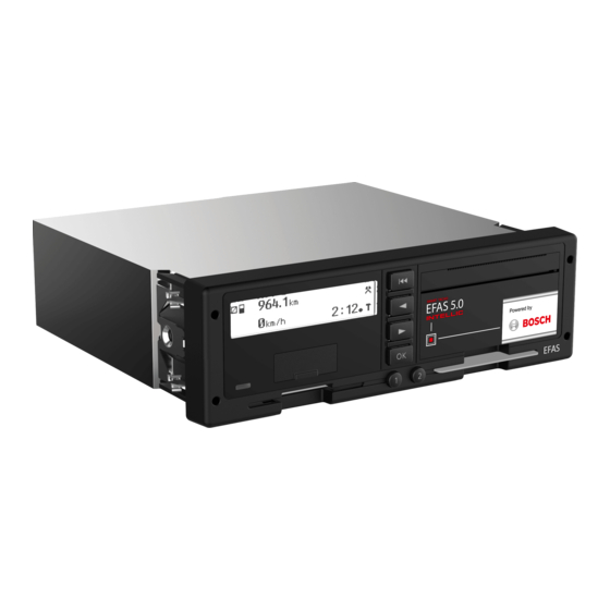
Chapter 4 Control elements and displays The EFAS tachograph The EFAS has a two-line LCD display, two slots for tachograph smart-cards, a front-mounted interface for calibration and down- loading, a printing module, and 6 operating keys. It can be installed in a standard-sized car stereo slot. Warning alerts can be emitted optically and acoustically. -
Page 18: Card Readers
The individual keys have the following functions: Meaning Description Key for driver 1 Referred to in the text below as: By briefly pressing the button, the driver activity (working time, standby time and rest time) can be selected for driver 1. The activity only changes after the key is released. Pressing the key for at least 1.5 seconds when the vehicle is stationary requests the card to be ejected from slot 1. -
Page 19: Display
Display The EFAS tachograph has an alphanumeric monochrome graphics-capable LCD. The color of the back-lighting is a device option and is set at the factory. It cannot be altered subsequently. Figure 3 — Alphanumeric display Text is displayed in the local language as configured. The language is set based on the local language of the driver’s or workshop smart-card or it can be selected via the main menu. -
Page 20: Printer Paper Container
Tone/series of tones Meaning / Operating state Blinks RED 1x long, 2x short Event or malfunction message as per REG (EC) No. 1360/ 2002. LED blinks for a maximum of 30 seconds until the cause of the alarm is acknowledged with OK. Alarm output pin D4 is set to active. -
Page 21: Working With Menus
Table 2 — Pin assignment of the service port Assignment (view from front) Meaning Ground (GND) K-line data interface (bidirectional) RS232 data interface (RxD g receive) I/O signal for calibration (bidirectional) EFAS supply voltage less max. 3 V RS232 data interface (TxD g transmit) The calibration interface consists of the bidirectional K-line data interface (pin 2), the I/O signal line (pin 4) and power supply (pins 1 and 5). -
Page 22: Card Combinations And Their Effect On The Operating Mode
Table 3 — Operating modes - symbols Card type Operating mode Display symbol OPERATIONAL Driver smart-card CALIBRATION Workshop smart-card COMPANY Company smart-card CONTROL Control smart-card When a smart-card is being read by the device, the card symbol of the card-slot in question blinks. Note The EFAS tachograph will ignore invalid tachograph smart-cards. -
Page 23: Chapter 5 General Instructions Prior To Installation
Chapter 5 General instructions prior to installation Preparations for installation in the vehicle The following chapter describes the preparations required for installing the EFAS tachograph in the vehicle. Before the tacho- graph can actually be installed in a vehicle it is important to perform a careful (visual) inspection of the components present. 5.1.1 Receipt of device On receipt of the device, please check that the packaging of the goods is intact. -
Page 24: Device Versions
Date of manufacturing Product code EU serial number separation Intellic-serial-number with dots for optical Data Matrix of Intellic-serial-number Space for OEM data Figure 8 — EFAS type label EFAS is also available as a training device. It is denoted as such on the type label. Training devices are not intended for installation in vehicles, but only for the training of tachograph users. -
Page 25: Chapter 6 Installing And Commissioning
Chapter 6 Installing and commissioning This chapter describes how the EFAS tachograph is installed in a vehicle and how EFAS is put into operation. The main steps are the activation of the tachograph and its pairing with a motion sensor. Checks before installation Prior to installation of the EFAS tachograph in a vehicle, check that the type label and the seal are intact. -
Page 26: Pin Assignment For The Device
Figure 9 — Connector panel Warning The lines A5 and A6 must be wired for the correct operation. If the line A6 is not wired in the vehicle-side con- nector cable, a connection (bridge) between A5 and A6 must be produced. Affected are especially vehicles with 12 V power supply. -
Page 27: Protection Of Positive And Negative Pole
Table 8 — Pin assignment plug connector C Contact Direction Function Comment Cable cross-section - - - Not used - - - Not used y Engine speed signal y Digital input for engine-speed sensor 0.35 - 1 mm y Input signal for second y Digital input for a pulse signal with frequency pro- motion source... -
Page 28: Motion Sensor
6.2.3 Motion sensor The motion sensor must conform to EU regulations and must be a type approved for use with the EFAS device. Install the motion sensor in accordance with the manufacturer’s instructions. After the motion sensor has been installed, it can be connected to the sensor cable. -
Page 29: Installing The Battery
Warning When changing the battery, ensure that the tachograph EFAS is constantly connected to the supply voltage (12 V or 24 V via connector A, white). Otherwise, the warranty becomes invalid when the battery is removed, since the tachograph assumes that the cover has been opened without authorization.. Position the device in such a manner that the underside of the device is turned towards you. -
Page 30: Seals
Close the battery clip by inserting the two hooks under the nipples on the battery holder and interlock the hooks with each other. Run the battery cable under the retaining hooks of the mounting plate to prevent the battery cable from obstructing the movement of the orange actuator. -
Page 31: Figure 16 - "Welcome" Message
step: Switch on the device After the EFAS device has been connected to the on-board power supply, the “WELCOME“ message will be displayed until the tachograph has performed all initialization functions. The welcome message shows the date and the local time (in this case the preset UTC time): Figure 16 —... -
Page 32: Figure 21 - Prompt For Pin Input
Note When the workshop card is inserted in EFAS for the first time, the ITS release dialog is displayed. Note If no key is pressed within 30 seconds, an approximately 5 second acoustic warning signal will sound that can be acknowledged with the 9 key. The PIN input prompt will then be displayed continuously until the input is aborted using the keypad or until the vehicle starts moving. -
Page 33: Sample Printouts "Technical Data
step: Activation and automatic motion sensor pairing The EFAS tachograph is now activated. This process can take up to three minutes. A progress bar is displayed while this is hap- pening. No information on the progress of the pairing process is displayed. During this time, the tachograph is connected to the motion sensor to form a functional unit. -
Page 34: Before Activation
6.4.1.1 Before activation The printout “Technical data” of the EFAS does not refer to a calibration purpose. There is no information regarding the sensor. - Time of printout - Expression type: Technical data - Information on the VIN consists of “?” - Member State empty / Vehicle registration plate consists of “?”, if no information was provided on this before activation;... -
Page 35: Initial Installation
6.4.1.3 Initial Installation After activation, a full calibration must be performed (see Chapter 9). After removing workshop card, printout “Technical Data” contains a data set with the calibration purpose (2) “Initial installation”. With the exception of the number plate (incl. state), all calibration parameters must be entered. -
Page 36: Subsequent Entry Of The Official Number Plate
6.4.1.4 Subsequent entry of the official number plate In order for the vehicle to be allowed to participate in traffic on public roads, the official registration plate must be entered in the calibration data. If this is not done before activation or during the initial cal- ibration, the vehicle registration number, the addendum may be made in two ways: y By the vehicle owner using his company... -
Page 37: Manual Motion Sensor Pairing
Manual motion sensor pairing The motion sensor pairing process is launched automatically when the device is activated. Start the pairing manually if auto pairing was unsuccessful, e.g. if the motion sensor was not connected during activation, or if you need to repeat the pairing of EFAS with the motion sensor. -
Page 38: Installing The Dsrc Module
Figure 34 — Indication of allowed key input during workshop card ejection Installing the DSRC module To enable the remote communication function, the EFAS DSRC module must be connected to the EFAS Tachograph. This enables employees of the responsible control authorities to read tachograph information from passing vehicles. 6.6.1 Installation of the DSRC module according to EU regulation 2016/799 The module shall be placed in or near the centre of the windscreen of the vehicle. -
Page 39: Chapter 7 General Settings
Chapter 7 General settings The following general settings for EFAS can be changed with the menu: y Times format on the printouts y The display’s appearance y Acoustic signals y Time and date y Company lock y Automatic activity setting after ignition OFF/ON y Time before warning when speed limit is exceeded (>>... -
Page 40: Time Zone
7.1.2 Time zone The time-zone setting specifies the constant that is added to UTC time to display the local time. The value can be modified in steps of 30 minutes. The value for Central European Time (CET) is +1:00 hour. In order to make the setting, select OK g Settings g Clock g Time zone The active time-zone setting will be displayed: Figure 38 —... -
Page 41: Automatic Activity Setting After Ignition Off/On
Automatic activity setting after ignition OFF/ON EFAS is able to activate a preprogrammed activity (, or ) for the driver and/or co-driver when the ignition is turned on or off. Programming of the activities after ignition OFF/ON is only possible in the COMPANY or CALIBRATION operating modes, i.e. with a company smart-card or workshop smart-card inserted. -
Page 42: Fleet Management System Fms
Fleet Management System FMS The following functions are available when the FMS unit is attached to the EFAS device and activated: Remote download of driver smart-card data to the company server Remote download of mass memory data (vehicle data) Removing the printer paper container and inserting the printer paper roll This section explains how to remove the printer paper container in order to be able to insert a new paper roll. -
Page 43: Chapter 8 Parameter Configuration
Chapter 8 Parameter configuration In addition to the legally required calibration parameters described in Chapter 9, the tachograph EFAS supports additional parameters that can be set via the service port. The advanced parameters allow for adaptations to different types of vehicles, and additional functions supported by the EFAS tachograph can also be configured. -
Page 44: Nominal Voltage Of The Vehicle (On-Board Power Supply) (Rdi=0Xfda3)
Parameters for vehicle adaptation Settings/value ranges AUTO Wake-up via CAN-bus Wake up from standby not possible FD6B Wake-up via CAN message possible Source to reset the trip distance Reset via the CAN bus FD00 Reset via the tachograph menu (keypad) Configuration of lighting control Set brightness of EFAS by menu and pin A2 FD34... -
Page 45: Can-Bus Configuration Of The Auxiliary Can Expansion Bus (Can Aux)
8.3.3 CAN-bus configuration of the auxiliary CAN expansion bus (CAN AUX) This CAN bus is provided for additional functions such as connecting to remote data transfer equipment or to the DSRC module.. Configuration of the CAN bus and the role of certain CAN parameters is described separately in section 13.1. 8.3.4 Wake-up via CAN-bus (RDI=0xFD6B) This parameter determines whether the tachograph can be activated by messages on the CAN interface with the ignition off... -
Page 46: Selection Of Engine-Speed Data Source (Rci=0Xfd3A)
many calibration/programming devices do not allow for entries after the decimal point, so that the values require multiplication by a factor of 1000. Typical settings are: 0.001 pulses/rev, 5.796 pulses/rev, 6.000 pulses/rev, 8.000 pulses/rev, 8.138 pulses/rev, 10.000 pulses/rev , 12.217 pulses/rev Warning An incorrect parameter setting can lead to malfunction or damage to the transmission and other serious dis- turbances of the driving and braking functions. -
Page 47: Automatic Parameters Detection
Automatic Parameters Detection The tachograph is able to make a useful setting for some parameters by itself. The parameters that can be set automatically, are listed and marked in Table 10. The “automatic parameter detection“ function may be started via EFAS menu. It is highly recommended to start it only when the EFAS is installed within a vehicle, the ignition is switched on and a valid workshop card is inserted. - Page 48 8.4.1 RDI Printout of RDIs of current vehicle adjustment The printing of RDIs of current vehicle adjustment can only be done in calibration mode or in the unactivated mode of the EFAS Tachograph. Time of printout 26/04/2020 15:20 (UTC) ----------------------- Type of printout RDI...
-
Page 49: Chapter 9 Calibration
Chapter 9 Calibration EU Regulation 165/2014 defines the calibration of the tachograph as an update or confirmation of vehicle parameters, including the vehicle identification and vehicle characteristics to be stored in the mass memory, by use of the workshop card. Calibration must be performed following the installation of the EFAS device into the vehicle as part of its activation and also during its regular inspections. -
Page 50: Preparatory Actions
Preparatory actions 9.2.1 Visual inspection Prior to the actual inspection of the digital recording equipment, it is recommended to inspect the front of the tachograph first to check for visible damage before removing the digital tachograph. 9.2.2 Inspection of the seals and installation plaque After visual inspection of the front of the tachograph EFAS, other preliminary checks must be performed with respect to: The installation plaque being intact Plausibility of the data on the installation plaque... -
Page 51: Testing Of Gnss Module
transferred with the help of a standard serial cable connected to the service interface in the front panel of the EFAS device. To this end, please open the rubber cover located under the LCD display. The operation of the calibration and tachometer testing equipment depends on the instructions of the manufacturer in question. The EFAS Service Tool can also read and modify the statutory calibration parameters. -
Page 52: Chapter 10 Fault Diagnosis
Chapter 10 Fault diagnosis 10.1 Events, malfunctions, and operating instructions in general The tachograph EFAS monitors all relevant system functions of the tachograph system cyclically. This includes the tachograph EFAS itself with individual components such as printer, keyboard, display unit and card slots as well as the motion sensor con- nected and the instrument panel connected via the CAN bus. -
Page 53: Error Code Types
In addition to the code number, other information pertaining to the DTC is stored in the fault memory, e.g. whether the fault is still active at the time of inquiry or how frequently a DTC has been registered. Many inspection and programming devices display the value of the status byte in addition to the DTC. -
Page 54: Displays In The Calibration Mode And Before Activation
Explanation of the display: SrvID:S70 Service identifier (service ID number) Number of unacknowledged messages of the same type 22.06.19 12:03 Time and date of the first occurrence (#1) of the message DTCs are output on the display unit only if they are identical to events or malfunctions of type 1. For this purpose, use a suitable diagnostics device or the EFAS Service Tool to ensure that DTCs are stored in the device. -
Page 55: Tools For Error Diagnosis
there is a defect in the tachograph or on one of the individual components of the system. In this case, the components involved must be replaced. For more details see Chapter 11. 10.5 Tools for error diagnosis You can use test equipment or the EFAS Service Tool available from Intellic as a fault diagnosis tool. The EFAS Service Tool is a program that can be executed under the Microsoft operating system Windows on a desktop PC or a notebook. -
Page 56: Printer Test
10.6.2 Printer test The printer test enables the printout of test prints. The standard test printout consists of lines and blackened rectangles, which can be used to assess the printed image quality and the printer form feed. Other test printouts output the individual character sets of the device. -
Page 57: Keyboard Test
There is no separate test procedure for the contrast and brightness. Figure 56 — Display for contrast setting Figure 57 — Display for brightness setting Both settings can be made via the user menu using the keys or . The values can only be inspected visually by the person conducting the test. -
Page 58: Testing The Warning Lamp And The Acoustic Alarm
10.6.7 Testing the warning lamp and the acoustic alarm This test checks that the warning light in the front module and the integrated acoustic alarm are functioning. The test activates the warning light and acoustic alarm for one second. Then both signal components are restored to their status prior to the test. Note In this test there is no additional text visible on the display unit of the EFAS. -
Page 59: Testing The Rotational Speed Of The Output Shaft
Figure 62 — Testing the rotational speed of the output shaft Note Calculation of the number of revolutions: n = real time signal of the motion sensor (B3) [1/s] × 60 [s/min] × 1000 [revolutions] 10.6.12 Testing the motion sensor interface This test function is used to verify the motion sensor interface on pins B1 to B4. -
Page 60: Dsrc Test (Equipment For Remote Communication)
Table 14 — Display of the status of the GNSS test function EFAS display Meaning Top row: GNSS position: YES or NO (x) for the position indicator Position indicator: 0 ... Position not fixed 1 ... GPS fixed 2 ... Differential GPS fixed ... -
Page 61: Chapter 11 Repair Options
Chapter 11 Repair options If the tachograph EFAS is damaged mechanically or if the keyboard or the display is defective, then the tachograph must be replaced completely. Cards which have become stuck can be removed from the device. 11.1 Removing the tachograph Proceed as follows to remove the EFAS tachograph from the vehicle. -
Page 62: Replacing The Buffer Battery
Note Please take care not to inadvertently eject your workshop smart-card. If this should still happen, please mark the event in the protocol. The card that has jammed is ejected. Check the ejected card for contamination or mechanical damage. Also check if the card slot is dirty or whether foreign objects are inside. -
Page 63: Warranty
11.6 Warranty The manufacturer Intellic offers a two-year warranty period starting with the first activation of the device on all devices. Any operation on the device other than that mentioned above leads to the warranty being rendered invalid. When you send a device back to the manufacturer for repair, please enclose a detailed fault description along with it. Please enter the following information in the greatest possible detail: What was the nature of the malfunction? Which event and fault codes (EFT, DTC, service ID) were detected? -
Page 64: Chapter 12 List Of The Events/Malfunctions And Measures For Trouble-Shooting
Chapter 12 List of the events/malfunctions and measures for trouble-shooting Abbreviations and explanations: SrvID Service ID (EFAS service code) Event fault type, error code in accordance with EU Regulation (EC) No. 2016/799 Diagnostic trouble code (standardized automotive error code) Decimal (base 10 numeral system) Hexadecimal numeral system with a base of 16 (using characters 0 to 9 and A to F) 12.1 EFT summary table... -
Page 65: Overview Of Service Ids
Meaning SrvIDs (hex) 0x24 Unauthorized opening of the housing 0x25 Hardware sabotage 0x3x Vehicle unit error 0x30 No further details 0x31 Vehicle unit internal error S35, S41, S42, S43, S48, S81, S87, S92, S94, S95, S96, S97, S98, S99, S103, S105, S108, S112, S113, S114, S119 0x32 Printer error 0x33 Display error 0x34 Download error... - Page 66 SrvID Symbol Description and trouble-shooting Display text 80 00 002004 ! Interruption Meaning / Cause: An interruption of the supply voltage of the motion sensor of power supply longer than 200 ms has been detected and reported by the motion sensor. Measures: Measure the supply voltage of the motion sensor at the pins B1 and B2.
- Page 67 SrvID Symbol Description and trouble-shooting Display text 40 00 000200 ! Card Meaning / Cause: An invalid card has been inserted in the card slot 1. invalid The following causes are possible: The card has been inserted the wrong way round. (Symbol in the display for The card is not a tachograph card.
- Page 68 SrvID Symbol Description and trouble-shooting Display text 40 00 000200 ! Last use of card Meaning / Cause: A tachograph smart-card has been inserted into card slot 1 after not finished the card was previously inserted in another tachograph and was not closed down properly.
- Page 69 SrvID Symbol Description and trouble-shooting Display text 40 00 000200 ! Security Meaning / Cause: An error was detected while authenticating a tachograph card violation in card slot 1. In the case of this error it is unlikely that there is a defect in the card locking mechanism or the card reader of EFAS, since, in this cases other error codes are reported.
- Page 70 SrvID Symbol Description and trouble-shooting Display text 80 00 002380 ! Sensor data Meaning / Cause: The communication via the data channel (pin B4) between the error tachograph and the motion sensor is interrupted. The motion sensor is not responding or no motion sensor is connected. Measures: Connect and pair the motion sensor, if not yet done.
- Page 71 SrvID Symbol Description and trouble-shooting Display text 80 00 000800 ! Security Meaning / Cause: The tachograph has an error in the current time or has detected violation a malfunction in the integrated clock. Further data recording and finally Service! is no longer possible.
- Page 72 SrvID Symbol Description and trouble-shooting Display text 40 00 000A70 - - - Meaning / Cause: Communication on the CAN main vehicle bus (depending on the parameter setting at the A or C connector) of EFAS has mal- functioned or is not possible. The following causes are possible: No bus subscriber is connected or a bus subscriber is not supplied with voltage.
- Page 73 SrvID Symbol Description and trouble-shooting Display text 40 00 001177 - - - Meaning / Cause: The communication with the instrument panel / E-tachometer has malfunctioned or is interrupted. The connection between the instrument panel / E-tachometer and EFAS is monitored by the tachograph cyclically by means of a life sign message trans- mitted by the instrument panel / E-tachometer every second.
- Page 74 SrvID Symbol Description and trouble-shooting Display text 80 00 000D40 - - - Meaning / Cause: The calibration data are incorrect or incomplete at the end of a calibration procedure (e.g., after pulling out the workshop smart-card). At least one of the EC calibration parameters does not have a valid value or during the calibration procedure, setting a given value was rejected and finally not corrected.
- Page 75 SrvID Symbol Description and trouble-shooting Display text 40 00 000F00 Internal Device Meaning / Cause: Malfunction of the keyboard has been detected, i.e. at least one malfunction key remains continuously pressed. The tachograph assumes that a key has been pressed continuously if it remains pressed for more than two minutes.
- Page 76 SrvID Symbol Description and trouble-shooting Display text 80 00 001260 ! Driving without Meaning / Cause: The vehicle was moved although there was no valid tachograph a suitable card smart-card (driver’s card or workshop smart-card) inserted into card slot 1. If a valid driver or workshop card is inserted into card slot 1, this error message is displayed even if the vehicle has been moved and a non-driver card is inserted into card slot 2.
- Page 77 SrvID Symbol Description and trouble-shooting Display text Download Meaning / Cause: There is a malfunction while downloading data. malfunction Measures: Check the connection (cable and connector) to the front interface of the recording equipment. Check if the transmission equipment used is compatible with the recording equipment (check the manufacturer and software version used on the transmission equipment).
- Page 78 SrvID Symbol Description and trouble-shooting Display text 40 00 002280 ! Vehicle motion Meaning/Cause: EFAS has detected a relevant difference between the speed conflict values of the paired motion sensor and the speed rvalues of the SrvID: S83 GNSS receiver. According to CR (EU) 2016/799, a speed difference between these two motion sources is classified as relevant if the median value of the deviation is continuously above 10 km/h for 5 minutes in...
- Page 79 SrvID Symbol Description and trouble-shooting Display text 40 00 000200 ! Security Meaning / Cause: The integrity (authenticity) of the data on the tachograph card in violation card slot 1 is not assured. Errors were found in the data structure. The following causes are possible: A defective card locking mechanism of EFAS (a defect in the card reader is unlikely with such a fault, since in this case,...
- Page 80 SrvID Symbol Description and trouble-shooting Display text 40 00 000139 Internal device Meaning / Cause: A general internal device malfunction is at hand. EFAS has per- malfunction formed a restart as a consequence of an extraordinary event during program execution. Measures: If this fault continues to occur, the tachograph must be replaced.
- Page 81 SrvID Symbol Description and trouble-shooting Display text S107 Meaning / Cause: ! Manufacturer- Protocol entry after a software update. An update of EFAS oper- specific event ating system software is recorded with this event. Measure: None S108 40 00 000139 Internal device Meaning / Cause: The data of the battery-backup memory has been lost.
- Page 82 SrvID Symbol Description and trouble-shooting Display text S114 40 00 000139 Internal device Meaning / Cause: The temperature control of the EFAS is faulty or the temperature malfunction is too low. Measure: If this error occurs at normal temperature the tachograph has to be replaced.
- Page 83 SrvID Symbol Description and trouble-shooting Display text S132 ! dd.mm.yy Meaning / Cause: Is displayed xx days before the card expiry date (dd.mm.yy), Card expiration date where xx is determined by the parameter RDI = F993 (default = (slot 1) 60 days).
- Page 84 SrvID Symbol Description and trouble-shooting Display text S170 GNSS Meaning / Cause: The tachograph receives no data from the internal GNSS receiver. error Measure: If the error is still displayed after several ignition cycles, the GNSS receiver is not functioning properly and the tachograph must be replaced.
- Page 85 SrvID Symbol Description and trouble-shooting Display text S200 > Input error < Meaning / Cause: “SrvID:S200 see manual” With manual input of the driver’s activities the maximum number of 20 activity changes per shift has been exceeded. S201 > Company lock < Meaning / Cause: “SrvID:S201 see manual”...
-
Page 86: Dtc Overview Table
12.3 DTC overview table The following table lists an overview of the DTCs (type 2 codes) defined for the tachograph system in accordance with ISO 16844-7. Standard diagnostic tools, such as, for example, hand-held calibration instruments / tachograph tester, often display only the ISO code of a DTC without any associated explanation of the meaning. -
Page 87: Printout Of Service Ids
Meaning Service ID (hexadecimal) 40 00 004700 Malfunction in the recording equipment, pin C8 40 00 004800 Malfunction in the recording equipment, pin D1 40 00 004900 Malfunction in the recording equipment, pin D2 40 00 004A00 Malfunction in the recording equipment, pin D3 40 00 004B00 Malfunction in the recording equipment, pin D4 40 00 004C00 Malfunction in the recording equipment, pin D5 40 00 004D00 Malfunction in the recording equipment, pin D6... -
Page 88: Support During Installation And Operation Of The Tachograph
26/04/2020 15:25 (UTC) ----------------------- Printout type SrvId ------------------------ If a printout period has been defined, it is printed here. 25/04/2020 - 26/04/2020 ------------------------ Pictogram; start time of event/fault. 26/04/2020 10:34 EFT (hex); SrvId; Duration 31 00h01 -------------------- ######################## Marker for last SrvId... -
Page 89: Chapter 13 Interfaces
Chapter 13 Interfaces 13.1 CAN bus The following chapters provide an overview of the various CAN interfaces at the A and C plug connectors, the types of data transfer possible via CAN bus and relevant CAN parameters. 13.1.1 Overview The EFAS tachograph has two independent CAN interfaces. One CAN bus (the main vehicle bus) is intended for the exchange of data with an instrument panel or an electronic tachometer, as well as for the connection of diagnostic devices. -
Page 90: Data
The EFAS test functions for the CAN bus (CAN A Test and CAN C Test) can support the determination of the correct termination. CAN A On delivery, EFAS is connected to CAN bus A, i.e. the terminating resistor is switched in. To remove the terminating resistor on CAN bus A, use a suitable tool to remove the integrated fuse on the EFAS connector panel. -
Page 91: Can Parameters
13.1.4 CAN parameters If the A plug connector’s CAN bus is to be used, a number of parameters must be set, so that the CAN bus fulfills the specific requirements of the respective vehicle type. The following functions are set with these parameters: Transmission rate (125 kbps, 250 kbps or 500 kbps) Length of CAN identifier (11 bits or 29 bits) Protocol selection “Standard protocol”... -
Page 92: Serial Interfaces D7 And D8
Table 20 — Manufacturer-specific CAN parameters CAN A / CAN C parameters Ranges of values RDI hex Selects the CAN main vehicle bus CAN main vehicle bus on connector A FD6E CAN main vehicle bus on connector C Basic configuration, A bus (bit rate and ID length setting) ON/OFF, 11/29 bit FD01 250 kbps or 500 kbps... -
Page 93: Protocol, Information Interface
The serial interface on pin D7 is pre-configured as a diagnostic interface. It can alternatively be used to connect an e-tachometer with K-line interface if the vehicle in which EFAS is to be installed does not have a CAN bus for connecting the tachometer/ instrument cluster to the tachograph. -
Page 94: Speed-Coding Output D6
13.3.2 Speed-coding output D6 For output D6, it can be selected whether the speed coded is calculated via the calibration parameter w/k (“B6/B7 identical”) or via an independent k (D6) factor (“pulse factor”). Using an inspection unit or EFAS Service Tool, it is possible to set the speed received by the ECU connected at D6 to correspond to the speed displayed and recorded at EFAS. -
Page 95: Chapter 14 Additional Data Recording
Chapter 14 Additional data recording EFAS facilitates the recording of additional data. Unlike mass memory data, which is required as per (EC) regulation 2016/799, this data can be deleted from the mass memory. There is still no obligation to archive this data. EFAS can additionally record the following data: Vehicle speed (v profile), Engine speed (n profile) -
Page 96: Logging The Two Status Inputs D1 And D2
The source can be configured with the EFAS Service Tool or a suitable testing / calibration device. In addition, at source C3, it is necessary to set a parameter - the so-called n-factor - with which EFAS can calculate an engine speed from the pulse frequency. Figure 69 —... -
Page 97: Chapter 15 Driver's Times Summary ( Icounter )
Chapter 15 Driver’s times summary ( iCounter ) The print out of current driving times can be done using the print function „ Driver’s times summary“. Remarks: y A question mark (“?”) is printed after a value when periods of unknown activity were consulted in order to calculate breaks an d rest periods. -
Page 98: Chapter 16 Updating The Efas Operating Software
Chapter 16 Updating the EFAS operating software In the course of technical improvements to the EFAS tachograph and due to changes in legal regulations, the operating software may be expanded, changed and improved. For this reason, the software can be updated in compliance with special security pre- cautions (“Software update”). -
Page 99: Finishing The Software Update
3. In the EFAS Service Tool, click on the item “SW update (tachograph)” and select the new tachograph software. If neces- sary, you should first transfer the update files (“credentials”) to the place suggested by the EFAS Service Tool on your PC. 4. -
Page 100: Chapter 17 National / Regional Abbreviations And European Time Zones
Chapter 17 National / regional abbreviations and European time zones The following table provides an overview of national and regional abbreviations, as well as time zones: Table 21 — National / regional abbreviations and European time zones Nation Abbreviation Time zone offset (without DST) Albania +01:00h Andorra... - Page 101 Nation Abbreviation Time zone offset (without DST) Catalonia +01:00h Castilla y León +01:00h Castile-La Mancha +01:00h Ceuta +01:00h Valencia +01:00h Extremadura +01:00h Galicia +01:00h Balearic Islands +01:00h Canary Islands +01:00h La Rioja +01:00h Madrid +01:00h Melilla +01:00h Murcia +01:00h Navarre +01:00h Basque Country +01:00h...
-
Page 102: Chapter 18 Technical Data
Chapter 18 Technical data The following table contains the EFAS tachograph’s most important technical data: Table 22 — Technical data Technical data Nominal power supply 12 V (typ. 13.8 V) or 24 V (typ. 27.0 V) Power supply range 8 V to 32 V (for max. 1 h, 36.2 V) Power consumption in operation at 12 V typ. -
Page 103: Chapter 19 Menu Structure In Efas
Chapter 19 Menu structure in EFAS The following figure depicts the EFAS menu structure Figure 73 — EFAS menu structure Figure 73 is a representation of the menu structure in EFAS. Which of the menu items can be accessed depends on the operating mode as set by inserting certain types of tachograph smart-card. -
Page 104: Chapter 20 Symbols And What They Mean
Chapter 20 Symbols and what they mean This chapter provides an overview of all symbols and symbol combinations used by the EFAS tachograph in on-screen displays, or in printouts. 20.1 Persons, activities and operating modes Table 23 — Symbols for persons, activities and operating modes Symbol Person Activity... -
Page 105: Special Conditions
Symbol Devices Vehicle / vehicle unit GNSS-facility Equipment for remote communication ITS-interface 20.5 Special conditions Table 27 — Symbols for special conditions Symbol Specific conditions Recording equipment not required Ferry crossing / rail travel 20.6 Miscellaneous Table 28 —... -
Page 106: Time Intervals
20.8 Time intervals Table 30 — Symbols for time intervals Symbol Interval Daily Weekly Fortnightly From or until 20.9 Symbol combinations Table 31 — Symbol combinations Symbol Meaning Control location (manual specification) Location at the start of the working day ... -
Page 107: 20.11 Printouts
Symbol Meaning Fortnight’s driving time II 20.11 Printouts Table 33 — Symbols for printouts Symbol Meaning Daily driver activity printout from the smart-card 24h Daily driver activity printout from the internal memory 24h Printout of events and malfunctions from the smart-card !... -
Page 108: 20.13 Malfunction Messages
20.13 Malfunction messages Table 35 — Symbols for malfunction messages Symbol Malfunction Smart-card error (driver’s card slot) 1 Smart-card error (co-driver’s card slot) 2 Display malfunction 9 Download malfunction Printer malfunction Sensor malfunction Internal device malfunction in the tachograph ... -
Page 109: Purposes Of Calibration
Purposes of calibration Purpose of Description calibration VU activation First installation: first calibration of the VU after its activation Installation: first calibration of the VU in the current vehicle Periodic inspection of the VU Entry of VRN by a company Time adjustment without calibration (128) Change of seal(s) -
Page 110: List Of Abbreviations
List of abbreviations Abbreviation Description Adaptive Cruise Control Controller Area Network Decimal (base 10 numeral system) Daylight-saving time Diagnostic trouble code (standardized automotive error code) DSRC Dedicated Short Range Communication European Community Electronic control unit Event fault type, error code in accordance with EU Regulation (EC) No. 1360/2002 End of line European Union Fleet Management System... -
Page 111: List Of Figures
List of figures Figure 1 — Keys............................................7 Figure 2 — Card readers ........................................8 Figure 3 — Alphanumeric display ....................................9 Figure 4 — Red warning lights to display the operational status ........................9 Figure 5 — Printer paper container ....................................10 Figure 6 —... - Page 112 Figure 62 — Testing the rotational speed of the output shaft..........................49 Figure 63 — Display of measurements for the motion sensor interface ......................49 Figure 64 — Display of the back-up battery voltage..............................49 Figure 65 — Position of the card readers release lever ............................51 Figure 66 —...
-
Page 113: List Of Tables
List of tables Table 1 — Warning light and acoustic signals ................................9 Table 2 — Pin assignment of the service port ................................11 Table 3 — Operating modes - symbols ..................................12 Table 4 — Operating modes from tachograph smart-cards..........................12 Table 5 — Housing dimensions .....................................15 Table 6 —... -
Page 114: Index
Index Event messages Events Access rights Exceptions from the obligatory use Acoustic signals exceptions to the compulsory use Activating the recording equipment Exclusion of warranty Activities AETR agreement Automatic activity setting after ignition OFF/ON Factor for calculating the speed Automatic Parameters Detection Factory settings Fault diagnosis Calibrating the EFAS... - Page 115 National abbreviations Test drive National regulations Test equipment Nominal voltage of the vehicle Test functions Testing for digital inputs/outputs Testing the acoustic alarm Testing the engine-speed signal source Operating instructions Testing the internal battery Operating states Testing the motion sensor interface Output Shaft Speed Testing the on-board power supply Overview of Service IDs...