Sign In
Upload
Manuals
Brands
Agilent Manuals
Measuring Instruments
ESA-L E4411B
Agilent ESA-L E4411B Manuals
Manuals and User Guides for Agilent ESA-L E4411B. We have
4
Agilent ESA-L E4411B manuals available for free PDF download: User's/Programmer's Reference, Programmer's Manual, Getting Started Manual
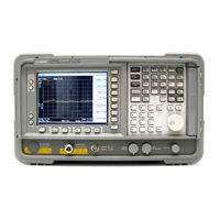
Agilent Technologies ESA-L E4411B Programmer's Manual (358 pages)
ESA Spectrum Analyzers
Brand:
Agilent Technologies
| Category:
Measuring Instruments
| Size: 3.62 MB
Table of Contents
Table of Contents
6
Programming Fundamentals
14
Creating Valid Commands
16
Command Notation Syntax
17
Special Characters in Commands
18
Parameters in Commands
19
Putting Multiple Commands on the same Line
21
SCPI Termination and Separator Syntax
21
Overview of GPIB
23
GPIB Instrument Nomenclature
23
GPIB Command Statements
23
Settings for the Serial Interface
25
Handshake and Baud Rate
25
Character Format Parameters
25
Overview of RS-232
25
Modem Line Handshaking
26
Data Transfer Errors
26
Printer Setup and Operation
27
Equipment
27
Interconnection and Setup
27
Testing Printer Operation
29
Status Registers
30
Use Status Registers to Determine the State of Analyzer Events and Conditions
31
What Are the Status Registers
32
How Do You Access the Status Registers
35
Using the Service Request (SRQ) Method
37
Generating a Service Request
37
Setting and Querying the Status Register
39
Details of Bits in All Registers
40
Status Byte Register
40
Service Request Enable Register
42
Standard Event Status Register
43
Standard Event Status Event Enable Register
45
Status:operation Register
46
Status:operation Condition Register
47
Status:operation Event Enable Register
48
Status:questionable Registers
49
Status:questionable:power Condition Register Bits
51
Status:questionable:frequency Condition Register Bits
51
Status:questionable:calibration Condition Register Bits
52
Status:questionable:integrity Condition Register Bits
53
Status:questionable:integrity:uncalibrated Condition Register Bits
55
Programming Examples
56
List of Programming Examples
57
Programming Examples System Requirements
58
C Programming Examples Using VTL
59
Typical Example Program Contents
59
Linking to VTL Libraries
60
Compiling and Linking a VTL Program
60
Example Program
62
Including the VISA Declarations File
62
Opening a Session
63
Device Sessions
63
Addressing a Session
65
Closing a Session
66
Using Marker Peak Search and Peak Excursion
67
Example
67
Using Marker Delta Mode and Marker Minimum Search
71
Performing Internal Self-Alignment
75
Reading Trace Data Using ASCII Format (HP-IB)
79
Reading Trace Data Using 32-Bit Real Format (HP-IB)
84
Real Format (HP-IB)
84
Reading Trace Data Using ASCII Format (RS-232)
89
Reading Trace Data Using 32-Bit Real Format (RS-232)
94
Using Limit Lines
99
Measuring Noise
104
Entering Amplitude Correction Data
108
Status Register-Determine When a Measurement Is Done
112
Determine if an Error Has Occurred
118
Measuring Harmonic Distortion (HP-IB)
124
Measuring Harmonic Distortion (RS-232)
133
Making Faster Measurements (Multiple Measurements)
142
Programming Command Cross References
152
Functional Index to SCPI Subsection
153
Scpi Sections and Subsections
158
Language Reference SCPI Sections and Subsections
159
Scpi
159
Subsystem/Subsection
159
IEEE Common Commands
160
Calibration Query
160
Clear Status
160
Standard Event Status Enable
160
Standard Event Status Register Query
161
Identification Query 094
161
Instrument State Query
161
Operation Complete
162
Query Instrument Options
162
Recall
162
Reset
163
Save
163
Service Request Enable
163
Read Status Byte Query
163
Trigger
164
Self Test Query
164
Wait-To-Continue
164
Abort Subsystem
165
Abort
165
Calculate Subsystem
166
Ndbpoints
166
Ndbresults
166
Ndbstate
167
Test Current Trace Data against All Limit Lines
167
Calculate:lline Subsection
167
Calculate
167
Calculate:lline
172
Calculate:marker Subsection
174
Calculate:marker
174
Calculate:ntdata Subsection
186
Calculate:ntdata
186
Calibration Subsystem
187
Align All Instrument Assemblies
187
Set Auto Align Mode All or Not RF
187
Calibration
187
Automatic Alignment
188
Return to the Default Alignment Data
188
Align FM Demodulation
188
Query the Internal or External Frequency Reference
188
Coarse Adjust the Frequency Reference
189
Fine Adjust the Frequency Reference
189
Select the Frequency Corrections
189
Align the RF Circuitry
189
Select the Source State for Calibration
190
Calibrate the Tracking Generator
190
Configure Subsystem
192
Configure the Adjacent Channel Power Measurements
192
Configure the Channel Power and Density Measurements
192
Configure the Emission Bandwidth Measurements
192
Configure the Harmonic Distortion Measurements
192
Configure the OBW and Transmit Frequency Error Measurements
192
Couple Subsystem
193
Couple the Function to Other Settings
193
Couple
193
Display Subsystem
194
Display Viewing Angle
194
Date and Time Display Format
194
Date and Time Display
194
Display Annotation Title Data
195
Turn the Entire Display On/Off
195
Window Annotation
195
Display
195
Trace Graticule Display
196
Trace X-Axis Scale Offset
196
Set the Display Line
196
Control the Display Line
197
Normalized Reference Level
197
Normalized Reference Level Position
197
Reference Level Auto Ranging
198
Trace Y-Axis Amplitude Scaling
198
Trace Y-Axis Frequency Scaling
198
Trace Y-Axis Reference Level
199
Trace Y-Axis Reference Level Offset
199
Vertical Axis Scaling
200
Fetch Subsystem
201
Return Main, Lower, and Upper Channel Power
201
Return Main Channel Power
201
Return Lower Channel Power
201
Return Upper Channel Power
202
Return Channel Power and Density
202
Return Channel Power
202
Return Channel Power Density
202
Return Emission Bandwidth
202
Return Harmonic Amplitudes
202
Return Harmonic N Amplitude
203
Return % Total Harmonic Distortion
203
Return Harmonic Frequency List
203
Fetch
203
Return Harmonic N Frequency
204
Return Fundamental Frequency
204
Return OBW and Transmit Frequency Error
204
Return Occupied Bandwidth
205
Return Transmit Frequency Error
205
Format Subsystem
206
Byte Order
206
Numeric Data Format
206
Format
206
Hcopy Subsystem
209
Abort the Print
209
Printer Type
209
Color Hard Copy
209
Hcopy
209
Print a Hard Copy
210
Form Feed the Print Item
210
Page Orientation
210
Number of Items Printed on a Page
210
Initiate Subsystem
212
Continuous or Single Measurements
212
Take New Data Acquisitions
213
Initiate
213
Restart Measurement
214
Input Subsystem
215
Input Port Coupling
215
Select Internal or External Mixer
215
Input
215
Select Mixer Type
216
Clear the Input Overload
216
Instrument Subsystem
217
Select Application
217
Measure Subsystem
218
Measure Main, Lower, and Upper Channel Power
218
Measure Main Channel Power
218
Measure Lower Channel Power
218
Measure Upper Channel Power
219
Measure Channel Power and Density
219
Measure Channel Power
219
Measure Channel Power Density
219
Measure Emission Bandwidth
219
Return Harmonic Amplitudes
219
Return Harmonic N Amplitude
220
Return % Total Harmonic Distortion
220
Return Harmonic Frequency List
220
Return Harmonic N Frequency
221
Return Fundamental Frequency
221
Measure OBW and Transmit Frequency Error
221
Measure Occupied Bandwidth
222
Measure Transmit Frequency Error
222
Mmemory Subsystem
223
Catalog the Selected Memory Location
223
Copy a File
223
Move Data to File
224
Delete a File
224
Load a Corrections Table from a File
224
Load a Limit Line from Memory to the Instrument
224
Instrument
224
Load an Instrument State from a File
225
Load a Trace from a File to the Instrument
225
Create a New Directory
226
Delete a Directory
226
Store a Corrections Table to a File
226
Store a Limit Line in a File
227
Store a Screen Image in a Graphic File
227
Store an Instrument State in a File
227
Store a Trace in a File
227
Output Subsystem
228
Turn Output On/Off
228
READ Subsystem
229
Measure Main, Lower, and Upper Channel Power
229
Measure Main Channel Power
229
Measure Lower Channel Power
229
Measure Upper Channel Power
229
Measure Channel Power and Density
230
Measure Channel Power
230
Measure Channel Power Density
230
Measure Emission Bandwidth
230
Return Harmonic Amplitudes
230
Return Harmonic N Amplitude
231
Return % Total Harmonic Distortion
231
Return Harmonic Frequency List
231
Return Harmonic N Frequency
232
Return Fundamental Frequency
232
Measure OBW and Transmit Frequency Error
232
Measure Occupied Bandwidth
233
Measure Transmit Frequency Error
233
Sense Subsystem
234
[:Sense]:Acpower Subsection
235
[:Sense]:Average Subsection
236
[:Sense]:Bandwidth Subsection
237
[:Sense]:Chpower Subsection
239
[:Sense]:Correction Subsection
240
[:Sense]:Demod Subsection
243
[:Sense]:Detector Subsection
245
[:Sense]:Ebwidth Subsection
245
[:Sense]:Frequency Subsection
247
[:Sense]:Harmonics Subsection
250
[Sense]:Mixer Subsection
252
[:Sense]:Obwidth Subsection
255
[:Sense]:Power Subsection
256
[:Sense]:Sidentify Subsection
258
[:Sense]:Sweep Subsection
260
Source Subsystem
264
Sets the Output Power Offset Correction
264
Source Attenuation
264
Automatic Source Attenuation
265
Sets the Output Power
265
Sets the Source Output Power Mode
265
Set the Source Sweep Power Range
266
Set the Output Power at the Start of the Sweep
266
Set the Output Power to Step Automatically
266
Set the Output Power Step Size
267
Set the Source Sweep Power Range
267
Output Power Tracking
267
Output Power Tracking Peak
268
Status Subsystem
269
Operation Condition Query
269
Operation Enable
269
Operation Event Query
269
Operation Negative Transition
270
Operation Positive Transition
270
Preset the Status Byte
270
Status:questionable Subsection
271
Sweep Subsystem
280
Sweep Points
280
System Subsystem
281
GPIB Address
281
Serial Port DTR Setup
281
Serial Port RTS Setup
282
Serial Port Baud Rate Setup
283
Serial Port Receive Pace Setup
283
Hardware Configuration Query
284
Serial Port Transmit Pace Setup
284
Display System Configuration
285
Display the Hardware Configuration
285
Set Date
285
System Configuration Query
285
Error Information Query
286
Host Identification Query
286
License Key - Install Application/Option
286
Delete a License Key
287
Query Instrument Options
287
Power on Elapsed Time
287
Power on Time
287
Power on Type
288
Enable If/Video/Sweep Output Ports
288
Preset
288
Factory Preset (no *RST)
288
Persistent, Which Means that It Retains the Setting
288
Previously Selected, Even through a Power Cycle
288
Persistent State Reset
289
Save User Preset
289
Preset Type
289
Speaker Control
289
Factory Preset (no *RST)
289
Front Panel Access
289
Set Time
290
SCPI Version Query
290
Persistent, Which Means that It Retains the Setting
289
Previously Selected, Even through a Power Cycle
289
Trace Subsystem
291
Copy Trace
291
Transfer Trace Data
291
Exchange Traces
292
Trace Math Add
292
Mean Trace Data
293
Query the Signal Peaks
293
Query Number of Peaks Found
293
Peak Sorting
293
Smooth Trace Data
294
Number of Points for Smoothing
295
Trace Math Subtract
296
Trace Math Subtract from Display Line
296
Select Trace Display Mode
296
Trigger Subsystem
298
External Trigger, Line and TV Trigger Delay Value
298
External Trigger, Line and TV Trigger Delay Enable
298
External Trigger Slope
298
Trigger Offset
299
Trigger Offset On/Off
300
Trigger Source
300
Set TV Field Mode
301
Set TV Line Number for Synchronization
302
Set Analyzer for TV Picture Monitoring
302
Set the Video Waveform Sync. Pulse Direction
302
Select TV Signal Path
303
Select TV Standard
303
Video Trigger Level Amplitude
304
Video Trigger Level Frequency
305
UNIT Subsystem
306
Select Power Units of Measure
306
Agilent 8590/ESA Spectrum Analyzers Programming Conversion Guide
307
Error Messages
309
Status Messages
311
Informational Messages
316
Error Queues
321
Error Message Format
322
Error Message Types
323
No Error
325
To -400
326
Query Errors
326
To -200
328
Execution Error Messages
328
Execution Error Message Descriptions
328
To -100
329
Command Errors
329
Device-SpecifiC Errors
334
Greater than 1000: Personality SpecifiC Error Messages
344
Advertisement
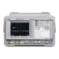
Agilent Technologies ESA-L E4411B User's/Programmer's Reference (426 pages)
Core Spectrum Analyzer Functions
Brand:
Agilent Technologies
| Category:
Measuring Instruments
| Size: 6.83 MB
Table of Contents
Table of Contents
5
Safety Information
2
What Is in this Book
36
AMPLITUDE y Scale
40
Auto Couple
54
Bk Sp (Backspace)
61
Bw/Avg
62
Det/Demod
66
Display
73
Enter
81
File
83
Freq Count
97
FREQUENCY Channel
98
Help
101
Input/Output
102
Marker
107
Marker
112
MEASURE (Spectrum Analysis Mode)
113
Meas Control
114
Mode
115
Next Window
116
Peak Search
117
Preset
122
Print
127
Print Setup
128
Restart
130
Return
131
Save
132
Single
133
Source
134
SPAN X Scale
139
Standby
144
Sweep
145
System (Local)
155
Tab Keys
166
Trace/View
167
Trig
171
UP) and ⇓ (DOWN) Arrow Keys
176
Viewing Angle
177
Zoom
178
Creating Valid Commands
181
Command Notation Syntax
182
Special Characters in Commands
183
Parameters in Commands
184
Improving Measurement Speed
187
Disable the If/Video/Sweep Output Ports
188
Avoid Unnecessary Use of *RST
189
Putting Multiple Commands on the same Line
190
Overview of GPIB (Option A4H)
192
Overview of RS-232 (Option 1AX)
194
Modem Line Handshaking
195
Status Registers
197
Use Status Registers to Determine the State of Analyzer Events and Conditions
198
How Do You Access the Status Registers
201
Using the Service Request (SRQ) Method
203
Setting and Querying the Status Register
204
Details of Bits in All Registers
205
Service Request Enable Register
206
Standard Event Status Register
207
Standard Event Status Event Enable Register
209
Status:operation Condition and Event Enable Registers
211
Status:questionable Registers
212
Status:questionable:power Register
215
Questionable Status Event Enable Register
216
Questionable Status Power Condition and Event Registers
218
Status:questionable:frequency Register
219
Questionable Status Frequency Condition and Event Enable Registers
221
Status:questionable:calibration Register
222
Status:questionable:integrity:uncalibrated Register
225
Questionable Status Calibration Condition and Event Enable Registers
226
Status:questionable:integrity Register
228
Questionable Status Integrity Event Condition and Enable Registers
230
Scpi Sections and Subsections
233
SCPI Subsystem/Subsection
234
IEEE Common Commands
235
Standard Event Status Register Query
236
Operation Complete
237
Reset
238
Service Request Enable
239
Abort
240
Abort Subsystem
240
Calculate Subsystem
241
Ndbstate
242
Calculate:lline
243
Set Limit Line X-Axis Units
244
Control Limit Line Frequency Interpolation
245
Merge Additional Values into the Existing Limit Line
247
Display the Limit Line
248
Control Limit Line Testing
249
Calculate:marker
250
Markers All off on All Traces
250
Frequency Counter Marker Automatic Resolution
251
Marker Function
252
Marker Next Peak (Maximum) Search
253
Define Peak Excursion
254
Define Peak Search
255
Set Center Frequency to the Marker Value
256
Set Center Frequency Step Size to the Marker Value
257
Marker to Trace
258
Marker X Value
259
Span Markers Center Frequency X Position
260
Delta Pair Markers Stop Frequency X Position
261
Delta Pair Markers Start Frequency X Value
262
Marker Read y Value
263
Calculate:ntdata
264
Calibration Subsystem
265
Automatic Alignment
266
Query the Internal or External Frequency Reference
267
Align the RF Circuitry
268
Calibrate the Tracking Generator
269
Configure Subsystem
270
Couple
271
Couple Subsystem
271
Display Subsystem
273
Date and Time Display
274
Turn the Full Screen Display On/Off
275
Display Line Amplitude
276
IF Gain Auto/Reference Level Auto Ranging
277
Normalized Reference Level Position
278
Trace Y-Axis Reference Level
279
Trace Y-Axis Reference Level Offset
280
Vertical Axis Scaling
281
Format
282
Format Subsystem
282
Hcopy
285
Hcopy Subsystem
285
Print a Hard Copy
286
Printed Page Size
287
Initiate Subsystem
288
Take New Data Acquisitions
289
Restart the Measurement
290
Input Subsystem
291
Select Internal or External Mixer
292
Clear the Input Overload
293
Instrument Subsystem
294
Select Application
295
Mmemory Subsystem
297
Move Data to File
298
Load an Instrument State from a File
299
Make a Directory
300
Store a Limit Line in a File
301
Mmemory:store:trace <Label>,<File_Name
302
Output
303
Output Subsystem
303
[:Sense]
304
[:Sense]:Average
305
Turn Automatic Averaging On/Off
306
Type of Averaging for Measurements
307
Sense]:Bandwidth Subsection
309
Video Bandwidth Automatic
310
Sense]:Correction Subsection
312
Merge Additional Values into the Existing Amplitude Correction Data
313
Delete Amplitude Correction
314
Input Impedance Correction
315
Sense]:Demod Subsection
316
FM Demodulation Squelch
317
Demod Time
318
Sense]:Detector Subsection
319
Type of EMI Detection
320
View of EMI Detection
321
Immediate Auto-Range EMI Detector
322
Sense]:Frequency Subsection
323
Center Frequency Step Size
324
Full Frequency Span
325
Stop Frequency
326
Frequency Synthesis Mode
327
Sense]:Mixer Subsection
328
Set External Mixer Bias On/Off
329
Set External Mixer lo Harmonic Mode
330
Sense]:Power Subsection
331
Input Port Power Gain
332
Preselector Center
333
Sense]:Sidentify Subsection
334
Sense]:Sweep Subsection
336
Query Number of Segments
337
Merge Data with Segmented Sweep Data
338
Delete All Segmented Sweep Data
339
Set Frequency Domain Scale Type
340
Sweep Time
341
Sweep Time Mode
342
Time Gate Level (Option 1D6 Only)
343
Control Time Gate (Option 1D6 Only)
344
Source Subsystem
345
Automatic Source Attenuation
346
Sets the Source Output Power Mode
347
Set the Output Power at the Start of the Sweep
348
Set the Source Sweep Power Range
349
Status Subsystem
351
Operation Negative Transition
352
Status:questionable Subsection
353
Questionable Calibration Negative Transition
354
Questionable Enable
355
Questionable Frequency Enable
356
Questionable Frequency Positive Transition
357
Questionable Integrity Negative Transition
358
Questionable Integrity Uncalibrated Event Query
359
Questionable Negative Transition
360
Questionable Power Event Query
361
Questionable Positive Transition
362
GPIB Address
363
Serial Port RTS Setup
364
Serial Port Receive Pace Setup
365
Query License Key Information
366
Display System Configuration
367
Host Identification Query
368
Delete a License Key
369
Power on Time
370
Preset
371
Save User Preset
372
Copy Trace
373
Exchange Traces
374
Trace Math Add
375
Peak Sorting
376
Number of Points for Smoothing
378
Select Trace Display Mode
379
External Trigger, Line, and TV Trigger Delay Value
380
Trigger Offset
381
RF Burst Frequency Selectivity
382
RF Burst Relative Mode Setting
383
Trigger Source
384
Set TV Field Mode
385
Set TV Line Number for Synchronization
386
Select TV Signal Path
387
Video Trigger Level Amplitude
388
Video Trigger Level Frequency
389
UNIT Subsystem
390
What You will Find in this Chapter
392
Alpha Editor Menu
393
AMPLITUDE y Scale Menu
394
AMPLITUDE y Scale Page
395
Amplitude y Scale: Corrections Menu
395
Auto Couple Menu
396
Bw/Avg Menu
397
Det/Demod Menu
398
Display
399
File
402
Freq Count
403
FREQUENCY Channel Menu
404
Input/Output Menu
405
Marker
406
Marker → Menu
407
Peak Search Menu
408
Preset
409
Print Setup Menu
410
Source
411
SPAN X Scale
412
Sweep
413
System
414
Trace/View Menu
415
Trig
416
Agilent Technologies ESA-L E4411B Programmer's Manual (379 pages)
ESA Spectrum Analyzers
Brand:
Agilent Technologies
| Category:
Measuring Instruments
| Size: 12.15 MB
Table of Contents
Table of Contents
7
1 Programming Fundamentals
19
Creating Valid Commands
20
Command Notation Syntax
22
Special Characters in Commands
23
Parameters in Commands
24
Putting Multiple Commands on the same Line
26
SCPI Termination and Separator Syntax
26
Overview of GPIB 1-1
28
GPIB Instrument Nomenclature 1-1
28
GPIB Command Statements 1-1
28
Overview of
30
Handshake and Baud Rate 1-1
30
Character Format Parameters
30
Modem Line Handshaking 1-1
31
Data Transfer Errors 1-1
31
Printer Setup and Operation 1-1
32
Equipment
32
Interconnection and Setup
32
Testing Printer Operation
34
Use Status Registers to Determine the State of Analyzer Events and Conditions
36
What Are the Status Registers
37
How Do You Access the Status Registers
40
Using the Service Request (SRQ) Method
42
Generating a Service Request
42
Setting and Querying the Status Register 2-1
44
Details of Bits in All Registers 2-1
45
Status Byte Register 2-1
45
Service Request Enable Register 2-1
47
Standard Event Status Register 2-1
48
Standard Event Status Event Enable Register 2-1
50
Status:operation Register 2-1
51
Status:operation Condition Register 2-1
52
Status:operation Event Enable Register 2-1
53
Status:questionable Registers 2-2
54
Status:questionable:power Condition Register Bits 2-2
56
Status:questionable:frequency Conditio N Register Bits
56
Status :Questionable :Calibration Condition Register Bits 2-2
57
Status:questionable:integrity Condition Register Bits
58
3 Programming Examples List of Programming Examples
62
Programming Examples System Requirements
63
Linking to VTL Libraries
65
Compiling and Linking a VTL Program
65
Example Program
67
Including the VISA Declarations File
67
Opening a Session
68
Device Sessions
68
Addressing a Session
70
Closing a Session 3-1
71
Using Marker Peak Search and Peak Excursion Example
72
Example
72
Using Marker Peak Search and Peak Excursion
72
Using Marker Delta Mode and Marker Minimum Search 3-1
76
Performing Internal Self-Alignment
80
Reading Trace Data Using ASCII Format (GPIB)
84
Reading Trace Data Using 32-Bi T Real Format (GPIB)
89
Reading Trace Data Using ASCII Format (RS-232)
94
Reading Trace Data Using 32-Bit Real Format (RS-232)
99
Using Limit Lines 3-4
104
Measuring Noise
109
Entering Amplitude Correction Data
113
Status Register-Determine When a Measurement Is Done 3-5
117
Determine if an Error Has Occurred 3-6
123
This C Programming Example Does the Following
123
/* - Clears the Analyze R
129
Cl S
129
/* - Set the Analyzer to Single Sweep Mode
129
Init :Cont
129
Opens an HP-IB Session at Address 1
129
Resets the Analyzer
129
SENS :FREQ :CENT Freq
129
Cal :Sour :Stat on
129
The SCPI Instrument Commands Used Are Given as /* Reference
129
Trigger a Sweep /* INIT :IMM
129
Calc :Mark :X
130
Calc :Mark :Y
130
Close the Session
131
Include <Stdio .H
131
Advertisement
Agilent Technologies ESA-L E4411B Getting Started Manual (98 pages)
Spectrum Analyzer
Brand:
Agilent Technologies
| Category:
Measuring Instruments
| Size: 1.89 MB
Table of Contents
Table of Contents
3
1 Installation and Setup
5
Initial Inspection
7
Power Requirements
9
Checking the Fuse
10
AC Power Cord
11
Turning on the Analyzer for the First Time
14
Why Aren't All the Personality Options Loaded in Memory
15
Using an External Reference
15
Firmware Revision
16
Running Internal Alignments
17
Printer Setup and Operation
18
Protecting against Electrostatic Discharge
21
Safety Information
22
2 Front and Rear Panel Features
23
Front Panel Overview
24
Front-Panel Connectors and Keys
24
Display Annotations
28
Rear-Panel Features
31
Key Overview
36
Front and Rear Panel Symbols
38
3 Making a Basic Measurement
39
Using the Front Panel
41
Entering Data
41
Using Menu Keys
41
Presetting the Spectrum Analyzer
42
Creating a User Preset
42
Viewing a Signal
43
4 Viewing Catalogs and Saving Files
49
File Menu Functions
51
Locating and Viewing Files in the Catalog
51
Creating a Directory
53
Formatting a Floppy Disk
53
Saving a File
55
Step 1. Set up the Analyzer Trace
55
Step 2. Save the File
57
Loading a File
59
Renaming a File
61
Copying a File
62
Deleting a File
63
Using the Alpha Editor
64
5 Options and Accessories
65
Ordering Options and Accessories
66
Options
67
Option Descriptions
70
Accessories
83
50 Ohm/75 Ohm Minimum Loss Pad
83
75 Ohm Matching Transformer
83
AC Probe
83
AC Probe (Low Frequency)
83
Broadband Preamplifiers and Power Amplifiers
83
Carrying Strap (Part Number E4401-60028)
84
External Keyboard
84
GPIB Cable
84
USB/GPIB Cable
84
Hp/Agilent 11970 Series Harmonic Mixers
84
Hp/Agilent 11974 Series Preselected Millimeter Mixers
85
Agilent E1779B Battery Pack
85
Parallel Interface Cable
85
Printer
85
RF and Transient Limiters
85
RF Bridges
86
RS-232 Cable
86
Static Safe Accessories
86
6 In Case of Difficulty
87
Types of Spectrum Analyzer Messages
89
Before Calling Agilent Technologies
90
Check the Basics
90
Read the Warranty
91
Service Options
91
Connector Care
91
Contacting Agilent Technologies
91
Returning an Analyzer for Service
92
Advertisement
Related Products
Agilent Technologies E4418B
Agilent Technologies E4416A
Agilent Technologies E4419B
Agilent Technologies E4417A
Agilent Technologies E441XA CW
Agilent Technologies E4411-90047
Agilent Technologies E4411-60019
Agilent Technologies E4411A
Agilent Technologies E4445A PSA Series
Agilent Technologies E4405B-STD
Agilent Categories
Measuring Instruments
Laboratory Equipment
Test Equipment
Water Pump
Power Supply
More Agilent Manuals
Login
Sign In
OR
Sign in with Facebook
Sign in with Google
Upload manual
Upload from disk
Upload from URL