Table of Contents
Advertisement
Quick Links
Advertisement
Table of Contents
Troubleshooting

Related Manuals for Motorola MC92N0-G


Summary of Contents for Motorola MC92N0-G
- Page 1 MC92N0-G USER GUIDE...
- Page 3 MC92N0-G User Guide 72E-162536-05 Rev A August 2015...
- Page 4 MC92N0-G User Guide No part of this publication may be reproduced or used in any form, or by any electrical or mechanical means, without permission in writing from Zebra. This includes electronic or mechanical means, such as photocopying, recording, or information storage and retrieval systems. The material in this manual is subject to change without notice.
-
Page 5: Revision History
Revision History Changes to the original manual are listed below: Change Date Description -01 Rev. A 12/2012 Initial Release. -02 Rev. A 05/31/13 Add Windows Embedded Handheld support. -03 Rev. A 12/01/14 Zebra Rebranding -04 Rev. A 6/2015 Add new Standard Range and Mid-Range imagers. -05 Rev. - Page 6 MC92N0-G User Guide...
-
Page 7: Table Of Contents
Charging the Battery ..........................1-3 Charging the Main Battery and Memory Backup Battery ............... 1-3 Charging Spare Batteries ....................... 1-4 Removing the Main Battery ......................1-5 Starting the MC92N0-G ........................1-6 Calibrating the Screen ......................... 1-6 Windows Devices ........................... 1-6 Android Devices ..........................1-6 Checking Battery Status ........................ - Page 8 Keypads ............................1-11 Entering Data ............................1-12 Using a Wired Headset ........................1-12 Using a Bluetooth Headset ........................1-13 Chapter 2: Operating the MC92N0-G with Windows OS Introduction ............................2-1 Windows CE 7.0 ..........................2-1 Start Menu ............................. 2-2 Control Panel ..........................2-4 Windows Embedded Handheld ......................
- Page 9 Performing a Warm Boot ......................2-25 Performing a Cold Boot ......................2-25 Battery Health ............................2-26 Waking the MC92N0-G ........................2-26 Chapter 3: Operating the MC92N0-G with Android OS Introduction ............................3-1 Home Screen ..........................3-1 Status Bar ............................3-2 Status Icons ...........................
- Page 10 MC92N0-G User Guide Working with Albums ....................... 3-19 Share an Album ........................3-19 Get Album Information ......................3-20 Deleting an Album ........................3-20 Working with Photos ........................ 3-20 Viewing and Browsing Photos ....................3-20 Setting a Photo as a Contact Icon ................... 3-22 Share a Photo ..........................
- Page 11 Table of Contents ScanSample ............................4-6 Using the RS507 Hands-free Imager ....................4-7 Pairing the RS507 Hands-Free Imager using Android HID ..............4-7 Pairing the RS507 Hands-Fee Imager Using Android SSI ..............4-8 Chapter 5: Using Bluetooth on Windows Devices Introduction ............................
- Page 12 MC92N0-G User Guide Headset Services ........................5-27 Serial Port Services ......................... 5-28 ActiveSync Using Serial Port Services ..................5-28 Personal Area Network Services ..................... 5-29 A2DP/AVRCP Services ......................5-29 Connect to a HID Device ......................5-30 Pairing with Discovered Device(s) ....................5-30 Bluetooth Settings ..........................
- Page 13 Inserting and Removing a Battery ....................7-19 Battery Charging Indicators ......................7-19 Modem Dongle ............................ 7-21 Setup .............................. 7-22 Connecting to the MC92N0-G ....................7-22 Connecting to the Single Slot Serial/USB Cradle ..............7-23 Forklift Cradle ............................7-24 MC92N0-G Insertion and Removal ....................7-25 Using the Locking Mechanism ....................
- Page 14 MC92N0-G User Guide 43-Key Keypad ..........................B-5 53-Key Keypad ..........................B-8 3270 Emulator Keypad ........................B-11 5250 Emulator Keypad ........................B-14 VT Emulator Keypad ........................B-17 Keypad Special Functions ......................B-20 Special Characters ......................... B-21...
-
Page 15: About This Guide
Screens and windows pictured in this guide are samples and can differ from actual screens. Documentation Set The documentation set for the MC92N0-G is divided into guides that provide information for specific user needs. • MC92N0-G Quick Start Guide - describes how to get the MC92N0-G mobile computer up and running. -
Page 16: Configurations
Emulators, 53-key High Visibility Condensation Resistant configurations utilize desiccant located inside the MC92N0-G to capture internal moisture that forms when they are carried from a warm humid environment to a cold environment. Software Versions Windows Mobile and Windows CE This guide covers various software configurations and references are made to operating system or software versions for: •... -
Page 17: Android
NOTE By default, the Microsoft Bluetooth stack is enabled. BTExplorer application is only available when the StoneStreet One Bluetooth stack is enabled. Refer to the MC92N0-G Integrator Guide for information on selecting the Bluetooth stack. To determine the BTExplorer software version: On Windows Embedded Handheld devices, tap Start >... -
Page 18: Chapter Descriptions
Keypads, contains the keypad functions/special characters for the keypads. Notational Conventions The following conventions are used in this document: • “Mobile computer” refers to the Zebra MC92N0-G hand-held computer. • Italics are used to highlight the following: • Chapters and sections in this guide •... -
Page 19: Related Documents And Software
MC92N0-G Integrator Guide, p/n 72E-162537-xx • Enterprise Mobility Developer Kits (EMDKs), available at: http://www.zebra.com/support. • Device Configuration Package (DCP for MC92N0c70) and Platform SDK (PSDK92N0c70) for MC92N0-G with Windows CE 7.0, available at: http://www.zebra.com/support. • ActiveSync software, available at: http://www.microsoft.com. - Page 20 MC92N0-G User Guide...
-
Page 21: Chapter 1 Getting Started
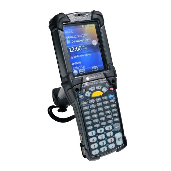
CHAPTER 1 GETTING STARTED Introduction This chapter explains how to install and charge the batteries, replace the strap and start the MC92N0-G for the first time. Indicator LED Bar Touch Screen Microphone Scan Button Keypad Headphone Jack Power Button Trigger... -
Page 22: Unpacking
NOTE Ensure the battery is fully inserted. Two audible clicks can be heard as the battery is fully inserted. A partially inserted battery may result in unintentional data loss. When a battery is fully inserted in a MC92N0-G for the first time, upon first power up, the device boots and powers on automatically. -
Page 23: Charging The Battery
Table 1-1 on page 1-4 for charge status indications). The main battery fully charges in less than four hours. The MC92N0-G can be charged using a cradle, the CAM, or the MSR with the appropriate power supply. The MC92N0-G is also equipped with a memory backup battery which automatically charges from the main battery whether or not the MC92N0-G is operating or is in suspend mode. -
Page 24: Charging Spare Batteries
Ensure the accessory used to charge the main battery is connected to the appropriate power source. Insert the MC92N0-G into a cradle or attach the appropriate snap-on module. The MC92N0-G starts to charge automatically. The amber charge LED, in the Indicator LED Bar, lights to indicate the charge status. See Table 1-1 for charging indications. -
Page 25: Removing The Main Battery
When the Indicator LED turns off, press the primary battery releases. The battery partially ejects from the MC92N0-G. Press the secondary battery release, on top of the battery, and slide the battery out of the MC92N0-G. Primary Battery Releases Secondary Battery Release... -
Page 26: Starting The Mc92N0-G
1 - 6 MC92N0-G User Guide Starting the MC92N0-G Press the red Power button to turn on the MC92N0-G. If the MC92N0-G does not power on, perform a cold boot. Resetting the MC92N0-G on page 2-24 for Windows devices and Resetting the Android Device on page 3-15 for Android devices. -
Page 27: Mc92N0-G Strap
1 - 7 MC92N0-G Strap The strap may be moved to either the left or right side of the MC92N0-G to suit user preferences. To reposition the strap: Slip the button through the end loop and remove from the handle. -
Page 28: Changing The Display Backlight Settings
1 - 8 MC92N0-G User Guide To set the MC92N0-G to turn off after a short period of non-use: On Windows CE devices, tap Start > Settings > Control Panel > Power > Advanced. On Windows Embedded Handheld devices, tap Start > Settings > System > Power > Advanced. -
Page 29: Changing The Keypad Backlight Settings
Getting Started 1 - 9 Changing the Keypad Backlight Settings Windows Devices To change the keypad backlight settings in order to conserve more battery power: On Windows CE devices, tap Start > Settings > Control Panel > Keylight > Battery Power. On Windows Embedded Handheld devices, tap Start >... -
Page 30: On Windows Ce Devices
1 - 10 MC92N0-G User Guide On Windows CE Devices WLAN Radio To turn off the WLAN radio tap the Fusion Signal Strength icon on the task tray and select Disable Radio. A red X appears across the icon indicating that the radio is disabled (off). -
Page 31: Led Indicators
Getting Started 1 - 11 LED Indicators The MC92N0-G has an LED Indicator Bar that contains LEDs that indicate scanning and charging status. Table 1-2 describes the LED indications. LED Indicator Bar MC92N0-G LEDs Indicator Bar Figure 1-8 MC92N0-G LED Indications... -
Page 32: Entering Data
You can use a mono headset for audio communication when an audio enabled application is used. To use a headset, plug the headset jack into the audio connector on the side of the MC92N0-G. Ensure that the MC92N0-G’s volume is set appropriately before putting the headset on. When a headset is plugged into the jack, the speakerphone is muted. -
Page 33: Using A Bluetooth Headset
Chapter 5, Using Bluetooth on Windows Devices for information on connecting a Bluetooth device to the MC92N0-G. Ensure that the MC92N0-G’s volume is set appropriately before putting the headset on. When a Bluetooth headset is connected the speakerphone is muted. - Page 34 1 - 14 MC92N0-G User Guide...
-
Page 35: Chapter 2 Operating The Mc92N0-Gwith Windows Os
Taskbar Figure 2-1 Status icons are shown in the taskbar to indicate present status of the MC92N0-G. Double tapping some status icons displays the corresponding setup window and enables you to change or adjust its settings from the window. Single tapping other status icons displays corresponding menus. -
Page 36: Start Menu
Description Icon AC Plug: Indicates that the battery is fully charged and the MC92N0-G is running on external power. Battery: This icon indicates that the battery is fully charged (100% charged). The battery status icons provide the battery status in 10% increments from 10% to 100%. - Page 37 Operating the MC92N0-G with Windows OS 2 - 3 Applications in the Programs Menu Table 2-2 Icon Description Icon Description BattSwap: Use to properly shutdown the Fusion Folder: Open the Wireless MC92N0 during battery replacement. Companion folder. Video Player: Play back video files.
-
Page 38: Control Panel
Bluetooth Device Properties: Launch brightness and power settings. the Bluetooth application. Certificates: See information about DataWedge: Sample scanning certificates installed on the MC92N0-G. application. Icon appears after installation. Date/Time: Change date, time and time Dialing: Set dialing properties for zone information. -
Page 39: Windows Embedded Handheld
Touch the screen to stop scrolling. Home Screen The default home screen on the MC92N0-G is the Windows Handheld Home screen. The Home screen contains a Status Bar at the top of the screen and a Tile Bar at the bottom of the screen. - Page 40 2 - 6 MC92N0-G User Guide Moving Today Screen Figure 2-3 Touch and hold the Information Status bar and move it up and down over an application name. Remove your finger and the Information Status bar and application name center in the screen.
-
Page 41: Classic Today Screen
Operating the MC92N0-G with Windows OS 2 - 7 Classic Today Screen The user can change to the classic Today screen layout that is used in Windows Mobile 6.1. Status Bar Today Screen Task Tray Tile Bar Classic Today Screen... -
Page 42: Status Bar
Bluetooth Communication: Indicates that the MC92N0-G is communicating with another Bluetooth device (Displays only if the StoneStreet One Bluetooth stack is enabled). ActiveSync: Indicates an active serial connection between the MC92N0-G and the development computer. DataWedge Running: Indicates that the DataWedge application is running. - Page 43 Operating the MC92N0-G with Windows OS 2 - 9 Status Bar Icons (Continued) Table 2-5 Icon Description Icon Description Notification that one or more e-mail/text There are more notification icons than can be messages were received. displayed. Connectivity Connection is active.
-
Page 44: Tile Bar
2 - 10 MC92N0-G User Guide Icon Bar Icons Table 2-6 Icon Description Magnify: Enlarges the screen. Connectivity: Displays the Connectivity dialog box. Volume: Displays the Volume dialog box. Power: Displays the Power window. Clock & Alarms: Opens the Clocks & Alarms window. - Page 45 Operating the MC92N0-G with Windows OS 2 - 11 Programs on the Start Screen (Continued) Table 2-7 Icon Description Icon Description Calendar: Keep track of appointments Settings: Open the Settings folder. and create meeting requests. Table 2-8 lists the default icons available on the Settings folder.
- Page 46 Description Icon Description Clock & Alarms: Set the device clock to Lock: Set a password for the MC92N0-G. the date and time of your locale. Alarms can also be set at specified days and times of a week. Home: Customize the appearance of the Sounds &...
- Page 47 Operating the MC92N0-G with Windows OS 2 - 13 Setting Applications (Continued) Table 2-8 Icon Description Icon Description Connections Folder Beam: Set the MC92N0-G to receive Connections: Set up one or more types of incoming beams. modem connections for your device, such...
-
Page 48: Speaker Icon
Lock the MC92N0-G by disabling key presses and screen tap or by requiring a password. Locking the MC92N0-G turns off keyboard and touch screen functionality. This is helpful when the MC92N0-G is turned on and you want to prevent accidental key presses. -
Page 49: Locking With Simple Pin
Operating the MC92N0-G with Windows OS 2 - 15 Lock Screen Figure 2-11 Slide the lock button left or right to unlock the screen. Locking with Simple PIN When the MC92N0-G is locked, the Lock screen appears. Simple PIN Lock Screen Figure 2-12 Enter the PIN and then tap Unlock. -
Page 50: Password Locking Setup
Password Locking Setup Use the Password window to set a password to disable unauthorized access to the MC92N0-G. If the MC92N0-G is configured to connect to a network, use a strong (difficult to figure out) NOTE password to help protect network security. Password cracking tools continue to improve and the computers used to crack passwords are more powerful than ever. -
Page 51: Using The Power Button
Using the Power Button Press the red Power button to turn the MC92N0-G screen on and off (suspend mode). The MC92N0-G is on when the screen is on and the MC92N0-G is in suspend mode when the screen is off. For more information, see... -
Page 52: Windows Embedded Handheld Devices
2 - 18 MC92N0-G User Guide Signal Strength Icon Wireless Application Menu Figure 2-15 Windows Embedded Handheld Devices On devices with Windows Embedded Handheld, access the Wireless Launcher from the Home NOTE screen. Select the Fusion plug-in and then tap the Fusion Menu button. -
Page 53: Connecting To The Internet
Operating the MC92N0-G with Windows OS 2 - 19 Wireless Launcher Window Connecting to the Internet To connect to the Internet on a WLAN when using Fusion Wireless Companion, ensure that the network card settings is set to Internet: Ensure Fusion is enabled and a profile is configured. -
Page 54: Fusion Setup
2 - 20 MC92N0-G User Guide Supported Applications (Continued) Table 2-9 Application Description Wireless Status Invokes the Wireless Status application which allows the user to view the status of the current wireless connection. Wireless Diagnostics Invokes the Wireless Diagnostics application which provides tools with which to diagnose problems with the wireless connection. - Page 55 Operating the MC92N0-G with Windows OS 2 - 21 Operating Mode Dialog Box Figure 2-18 Tap Next. The Security Mode dialog box displays. In the Security Mode drop-down list, select Legacy (Pre-WPA). Security/Authentication Dialog Box Figure 2-19 In the Authentication drop-down list, select None.
- Page 56 2 - 22 MC92N0-G User Guide WEP-40 WEP Keys Dialog Box Figure 2-21 In the Edit Key drop-down list, select the key to enter. In the Key field, enter 10 hexadecimal characters. In the Confirm field, re-enter the key. When the keys match, a message appears indicating that the keys match.
-
Page 57: Interactive Sensor Technology
It can also be used to keep the MC92N0-G active while it is in movement to prevent it from quickly going into suspend mode while in use. -
Page 58: Using A Bluetooth Headset
Resetting the MC92N0-G Windows CE Devices There are two reset functions, warm boot and cold boot. A warm boot restarts the MC92N0-G by closing all running programs. A cold boot also restarts the MC92N0-G, but erases all stored records and entries in RAM. Data saved in flash memory or a memory card is not lost. -
Page 59: Windows Embedded Handheld Devices
While the battery is partially released, simultaneously press and release the handle trigger and the Power button. Push the battery to fully re-insert it in the MC92N0-G. One audible click can be heard as the battery is fully inserted. The MC92N0-G reboots. -
Page 60: Battery Health
Guide. Waking the MC92N0-G The wakeup conditions define what actions wake up the MC92N0-G after it has gone into suspend mode. The MC92N0-G can go into suspend mode by either pressing the Power button or automatically by Control Panel time-out settings. These settings are configurable and the factory default settings are shown in Table 2-11. -
Page 61: Chapter 3 Operating The Mc92N0-Gwith Android Os
WITH ANDROID OS Introduction This chapter explains the physical buttons, status icons and controls on the MC92N0-G, how to use the MC92N0-G, including instructions for powering on and resetting, using the stylus and a headset, entering information and data capture. -
Page 62: Status Bar
Table 3-2 Icon Description Indicates that the Alarm is active. Indicates that all sounds except media and alarms are silenced and vibrate mode is active. Indicates that the MC92N0-G is in silent mode. Indicates that the battery is fully charged. -
Page 63: Notification Icons
Operating the MC92N0-G with Android OS 3 - 3 Status Icons (Continued) Table 3-2 Icon Description Indicates that the battery is partially drained. Indicates that the battery charge is low. Indicates that the battery charge is very low. Indicates that the battery is charging. -
Page 64: Managing Notifications
3 - 4 MC92N0-G User Guide Notification Icons (Continued) Table 3-3 Icon Description Indicates an upcoming event. Indicates that an open Wi-Fi network is available. Indicates that a song is playing. Indicates that a problem with sign-in or sync has occurred. -
Page 65: Quick Settings
Operating the MC92N0-G with Android OS 3 - 5 Notification Panel Figure 3-3 To respond to a notification, open the Notifications Panel and then touch a notification. The Notifications Panel closes and the subsequent activity is dependent on the notification. -
Page 66: Application Shortcuts And Widgets
3 - 6 MC92N0-G User Guide Quick Settings Figure 3-4 • Owner – Display the owner’s contact image. Touch to open the owner’s contact information. • Brightness – Opens the Brightness setting dialog box to set the screen brightness. •... -
Page 67: Moving Items On The Home Screen
Operating the MC92N0-G with Android OS 3 - 7 Moving Items on the Home Screen Touch and hold the item until it floats on the screen. Drag the item to a new location. Pause at the edge of the screen to drag the item onto an adjacent Home screen. -
Page 68: Removing A Folder
3 - 8 MC92N0-G User Guide Removing a Folder Touch and hold the folder icon until it enlarges and the device vibrates. Drag the icon to and release. Home Screen Wallpaper NOTE Use of Live Wallpaper may reduce battery life. -
Page 69: Using The On-Screen Keyboard
Operating the MC92N0-G with Android OS 3 - 9 • Double-tap - Tap twice on a web page, map, or other screen to zoom in and out. Using the On-screen Keyboard Use the on-screen keyboard to enter text in a text field. To configure the keyboard settings, touch (comma) >... - Page 70 3 - 10 MC92N0-G User Guide Applications (Continued) Table 3-4 Icon Description Calendar - Use to manage events and appointments. Clock - Use to schedule alarms for appointments or as a wake-up. DataWedge - Enables data capture using the imager.
-
Page 71: Accessing Applications
Operating the MC92N0-G with Android OS 3 - 11 Applications (Continued) Table 3-4 Icon Description RxLogger - Use to diagnose device and application issues. See the MC9200 Integrator Guide for more information. Search - Use the Google search engine to search the Internet and the MC9200. -
Page 72: Switching Between Recent Applications
3 - 12 MC92N0-G User Guide Application Shortcuts and Widgets on page 3-6 for information on creating a shortcut on NOTE the Home screen. Switching Between Recent Applications Touch and hold . A window appears on the screen with icons of recently used applications. - Page 73 Operating the MC92N0-G with Android OS 3 - 13 Lock Screen Figure 3-9 PIN Screen Figure 3-10 Pattern Screen Figure 3-11...
-
Page 74: Multiuser Mode
3 - 14 MC92N0-G User Guide Password Screen Figure 3-12 MultiUser Mode With MultiUser login, multiple users can log on to the device with each user having access to various applications and features. When enabled, the Login screen appears after powering on, resetting or after the device wakes from suspend mode. -
Page 75: Resetting The Android Device
Press the primary battery release on the MC92N0-G to partially eject the battery from the MC92N0-G. While the battery is partially released, simultaneously press and release the trigger and the Power button. Push the battery to fully re-insert it in the MC92N0-G. One audible click can be heard as the battery is fully inserted. -
Page 76: Applications
3 - 16 MC92N0-G User Guide NOTE If the user enters the PIN, password or pattern incorrectly five times, they must wait 30 seconds before trying again. If the user forgets the PIN, password or pattern contact the system administrator. -
Page 77: People
Operating the MC92N0-G with Android OS 3 - 17 (3) to view the internal storage root folder. (4) to view the SD card root folder. (5) to view the previous folder or to exit the application. Touch and hold an item to perform an operation on that item. Select one of the options from the File Operations menu:- •... -
Page 78: Editing People
3 - 18 MC92N0-G User Guide Touch Done. Editing People In the People application, touch tab. Touch a person to edit. Touch Touch Edit. Edit the contact information. Touch Done. Deleting People In the People application, touch tab. Touch a person to edit. -
Page 79: Working With Albums
Operating the MC92N0-G with Android OS 3 - 19 Gallery — Albums Figure 3-16 • Touch an album to open it and view its contents. The photos and videos in the album are displayed in chronological order. • Touch a photo or video in an album to view it. -
Page 80: Get Album Information
3 - 20 MC92N0-G User Guide Touch other albums as required. Touch . The Share menu opens. Touch the application to use to share the selected albums. Follow the instructions within the selected application. Get Album Information Touch Touch Touch and hold an album until it highlights. - Page 81 Operating the MC92N0-G with Android OS 3 - 21 Photo Example Figure 3-18 Swipe left or right to view the next or previous photo in the album. Turn the device to view the photo in upright (portrait) or sideways (landscape) orientation. The photo is displayed (but not saved) in the new orientation.
-
Page 82: Setting A Photo As A Contact Icon
3 - 22 MC92N0-G User Guide Touch Save to save a copy of the cropped photo. The original version is retained. Setting a Photo as a Contact Icon Touch Touch Touch an album to open it. Touch the photo to open it. -
Page 83: Working With Videos
Operating the MC92N0-G with Android OS 3 - 23 Working with Videos Use Gallery to view videos on the SD card and share videos. Watching Videos Touch Touch Touch an album to open it. Touch a video. Video Example Figure 3-20 Touch . -
Page 84: Deleting A Video
3 - 24 MC92N0-G User Guide Touch an album to open it. Touch a video to open it. Touch . The Share menu appears. Touch the application to use to share the selected video. The application selected opens with the video attached to a new message. -
Page 85: Sound Recorder
Operating the MC92N0-G with Android OS 3 - 25 DataWedge Demonstration Icons Table 3-5 Icon Description Not applicable. Toggles the data capture function between the internal scanner, imager or RS507 Hands-free Bluetooth imager (if connected). Toggles between normal scan mode and picklist mode when using the imager to capture bar code data. -
Page 86: Ptt Audible Indicators
3 - 26 MC92N0-G User Guide • Private Response: Press and hold the red Private Call button to respond to the originator of the last broadcast or to make a Private Response. PTT Audible Indicators The following tones provide helpful cues when using the voice client. -
Page 87: Notification Icons
Operating the MC92N0-G with Android OS 3 - 27 Notification Icons Indicates the current state of the PTT Express Voice client. PTT Express Default User Interface Descriptions Table 3-7 Status Icon Description Indicates that PTT Express Voice client is disabled. -
Page 88: Creating A Group Call
3 - 28 MC92N0-G User Guide Creating a Group Call Press and hold the green Group Call button and listen for the talk tone to play. If a busy tone is heard, release the green Group Call button and wait a moment before making another attempt. -
Page 89: Rxlogger
Operating the MC92N0-G with Android OS 3 - 29 MLog Manager Figure 3-26 RxLogger RxLogger is a comprehensive diagnostic tool that provides application and system metrics. It allows for custom plug-ins to be created and work seamlessly with this tool. RxLogger is used to diagnose device and application issues. -
Page 90: Disabling Elemez Data Collection
3 - 30 MC92N0-G User Guide Elemez Application Figure 3-28 Disabling Elemez Data Collection The user can disable the Elemez application from collection specific data in the background and sending it to Zebra Technologies. Touch > Apps. Swipe left or right until the ALL tab displays. -
Page 91: Terminal Emulation
Operating the MC92N0-G with Android OS 3 - 31 Touch > Touch Enable Elemez. Terminal Emulation The Wavelink Terminal Emulation application provides a solution for accessing and managing connections to applications resident on host systems using 5250, 3270 and VT emulation. -
Page 92: Scan And Connect To A Wi-Fi Network
(DHCP) protocol. To configure the MC92N0-G with a fixed internet protocol (IP) address, See Configuring the Device to Use a Static IP Address on page 3-37. In the Wi-Fi setting field, Connected appears indicating that the MC92N0-G is connected to the WLAN. -
Page 93: Configuring A Wi-Fi Network
Operating the MC92N0-G with Android OS 3 - 33 Configuring a Wi-Fi Network To set up a Wi-Fi network: Touch Touch Wi-Fi. Slide the switch to the ON position. The device searches for WLANs in the area and lists them on the screen. - Page 94 3 - 34 MC92N0-G User Guide WLAN Network Security Dialog Box Figure 3-32 If the network security is WEP or WPA/WPS2 PSK, enter the required password and then touch Connect. If the network security is 802.1x EAP: • Touch the EAP method drop-down list and select PEAP, TLS, TTLS, LEAP or FAST.
-
Page 95: Manually Adding A Wi-Fi Network
Operating the MC92N0-G with Android OS 3 - 35 • If desired, in the Anonymous identity text box, enter an anonymous identity username. • If required, in the Password text box, enter the password for then given identity. NOTE By default, the network Proxy is set to None and the IP settings is set to DHCP. See... -
Page 96: Configuring For A Proxy Server
3 - 36 MC92N0-G User Guide By default, the network Proxy is set to None and the IP settings is set to DHCP. See Configuring for a Proxy Server on page 3-36 for setting connection to a proxy server and see... -
Page 97: Configuring The Device To Use A Static Ip Address
Operating the MC92N0-G with Android OS 3 - 37 Configuring the Device to Use a Static IP Address By default, the device is configured to use Dynamic Host Configuration Protocol (DHCP) to assign an Internet protocol (IP) address when connecting to a wireless network. To configure the device to connect to a network using a static IP address: In the network dialog box, touch a network. - Page 98 3 - 38 MC92N0-G User Guide • General • Network notification - When enabled, notifies the user when an open network is available. • Keep Wi-Fi on during sleep - Opens a menu to set whether and when the Wi-Fi radio turns off.
-
Page 99: Remove A Wi-Fi Network
Operating the MC92N0-G with Android OS 3 - 39 Fusion Status Screen Figure 3-36 • About • Version - Displays the current Fusion information. Remove a Wi-Fi Network To remove a remembered or connected network: Touch Touch Wi-Fi. In the Wi-Fi networks list, touch and hold the name of the network. - Page 100 3 - 40 MC92N0-G User Guide...
-
Page 101: Chapter 4: Data Capture
Successful decode. Laser Scanning To read a bar code, a scan-enabled application is required. The MC92N0-G contains the DataWedge and ScanSample (Windows CE devices only) applications that allows the user to enable the scanner to decode bar code data and display the bar code content. See... -
Page 102: Scanning Considerations
Launch a scanning application or a sample scanning application (DataWedge or ScanSample). Point the exit window on the top of the MC92N0-G at a bar code. Press the trigger or scan button. Ensure the red scan beam covers the entire bar code. The Scan LED Indicators illuminate red to indicate that the laser is on. -
Page 103: Operational Modes
(either 1D or 2D). • Image Capture Mode: Use this mode to capture an image within the MC92N0-G’s field of view. This is useful for capturing signatures or images of items like damaged boxes. - Page 104 4 - 4 MC92N0-G User Guide Standard Range/Mid-Ranger Imager Aiming Pattern Figure 4-2 Long Range Imager Aiming Pattern Figure 4-3 Standard Range/Mid-Range Imager Pick List Mode with Multiple Bar Codes Figure 4-4...
-
Page 105: Image Capture
To capture an image, an image capture application is required. Launch an image capture application. Point the exit window on the top of the MC92N0-G toward the object to capture. Press the trigger or scan button. The captured image appears on the screen. -
Page 106: Disable Datawedge
4 - 6 MC92N0-G User Guide Touch Touch Touch Settings. Touch the DataWedge enabled checkbox. A blue checkmark appears in the checkbox indicating that DataWedge is enabled. Touch Disable DataWedge To disable DataWedge on Windows CE or Embedded Handheld devices: On Windows CE devices, double-tap the icon on the desktop or tap Start >... -
Page 107: Using The Rs507 Hands-Free Imager
Tap Pairing Barcode. A bar code displays. NOTE If the MC92N0-G with Windows CE is set to VGA mode the RS507 cannot read the bar code due to the smaller bar code size. Refer to the RS507 Hands-free Imager Product Reference Guide for instruction for printing a pairing bar code. -
Page 108: Pairing The Rs507 Hands-Fee Imager Using Android Ssi
4 - 8 MC92N0-G User Guide Remove the battery from the RS507. Re-install the battery into the RS507. On the MC9200-G, touch Touch Bluetooth. Touch SCAN FOR DEVICES. The device begins searching for discoverable Bluetooth devices in the area and displays them under AVAILABLE DEVICES. -
Page 109: Chapter 5 Using Bluetooth On Windows Devices
Zebra mobile computers to operate in any infrastructure. The Bluetooth radio in this MC92N0-G operates as a Class 2 device power class. The maximum output power is 2.5mW and the expected range is 32.8 feet (10 meters). A definition of ranges based on power class is difficult to... -
Page 110: Security
The Microsoft stack supports Smart-pairing. For detailed information, refer to the Microsoft MSDN. Security Mode 3 (Link Level Encryption) The MC92N0-G supports Security Level 3 (Link Level Encryption). Link level encryption is the data security process of encrypting information at the data link level as it is transmitted between two devices. -
Page 111: Bluetooth Configuration
Using Bluetooth on Windows Devices 5 - 3 Bluetooth Configuration By default, the MC92N0-G is configured to using the Microsoft stack. Refer to the MC92N0-G Integrator Guide, for information on switching between the Microsoft Bluetooth stack and the StoneStreet One Bluetooth stack. Table 5-1 list the services supported by the StoneStreet One Bluetooth stack and the Microsoft Bluetooth stack. -
Page 112: Bluetooth Power States
With Microsoft Bluetooth Stack NOTE If there is an active Bluetooth connection between the MC92N0-G and another Bluetooth device and there is no data activity, the MC92N0-G will timeout. However, if the user presses the Power button on the MC92N0-G, the MC92N0-G will suspend and upon receiving data from a remote Bluetooth device, the MC92N0-G will wake from suspend mode. -
Page 113: Btui Window
Tap the Back button to return to the MotoBTUI window. FIPS Configuration By default the MC92N0-G has a FIPS key installed. If required, the user can generate a new NOTE FIPS key. If a new key is generated on the MC67, the same key is required to be used on the other Bluetooth device. -
Page 114: Device Status
Locate the NewAESKey.reg file and tap the filename. The RegMerge confirmation box displays. Tap Yes. Perform a warm boot. Device Status Use the Device Status option to set if the MC92N0-G would be seem by other Bluetooth devices. Touch the Device Status option to toggle the MC92N0-G from Hidden to Discoverable. -
Page 115: Using Microsoft Bluetooth Stack With Windows Embedded Handheld
Turn off the Bluetooth radio to save power or if entering an area with radio restrictions (e.g., an airplane). When the radio is off, other Bluetooth devices cannot see or connect to the MC92N0-G. Turn on the Bluetooth radio to exchange information with other Bluetooth devices (within range). -
Page 116: Available Services
After the passcodes have been accepted on both sides, you have a trusted (“paired”) connection. Available Services NOTE Some devices might not require a PIN. This depends upon the device’s authentication. The MC92N0-G with Microsoft Bluetooth stack and Windows Embedded Handheld offers the following services: • OBEX Object Push via Beam •... -
Page 117: Serial Port Services
Select Beam File. The MC92N0-G searches for Bluetooth devices in the area. Tap Tap to send next to the Bluetooth device to send the file to. The MC92N0-G communicates with the device and send the file. When completed, Tap to send changes to Done. -
Page 118: Activesync Using Serial Port Services
5 - 10 MC92N0-G User Guide Tap Start > Settings > Connections tab > Bluetooth icon > Devices tab. Tap Add new device. The MC92N0-G begins searching for discoverable Bluetooth devices in the area. Select a device from the list. - Page 119 On the Allow connections to one of the following drop-down list, select the COM port with the number you noted earlier. On the MC92N0-G, tap Start > Programs > ActiveSync. Tap Menu > Connect via Bluetooth. Synchronization is automatically initiated. The ActiveSync icon appears on the lower right corner of the Today screen.
-
Page 120: Using Microsoft Bluetooth Stack With Windows Ce
Discovering Bluetooth Device(s) The MC92N0-G can receive information from discovered devices without bonding. However, once bonded, the MC92N0-G and a bonded device exchange information automatically when you turn the Bluetooth radio on. See Pairing with Discovered Device(s) on page 5-30 for more information. -
Page 121: Available Services
NOTE In order to connect to the Bluetooth device, the application must create the connection to the remote device. Please refer to the MSDN Help for detailed information. The MC92N0-G with Microsoft Bluetooth stack and Windows CE only supports the Serial Port service. -
Page 122: Using Bluetooth Stonestreet One Bluetooth Stack
Turn off the Bluetooth radio to save power or if entering an area with radio restrictions (e.g., an airplane). When the radio is off, other Bluetooth devices cannot see or connect to the MC92N0-G. Turn on the Bluetooth radio to exchange information with other Bluetooth devices (within range). -
Page 123: Modes
Discovering Bluetooth Device(s) The MC92N0-G can receive information from discovered devices without bonding. However, once bonded, the MC92N0-G and a bonded device exchange information automatically when you turn the Bluetooth radio on. See Pairing with Discovered Device(s) on page 5-30 for more information. - Page 124 5 - 16 MC92N0-G User Guide NOTE If favorite connections have already been created, the Favorites screen displays. If no favorite connections have been created, the New Connection Wizard screen displays. Tap Menu > New Connection.The New Connection Wizard appears.
- Page 125 Using Bluetooth on Windows Devices 5 - 17 Select Remote Device Window Figure 5-8 Select a device from the list and tap Next. The MC92N0-G searches for services on the selected Bluetooth device. Device Services Figure 5-9 NOTE If the MC92N0-G discovers a service but the service is not supported, the service icon is grayed-out.
-
Page 126: Available Services
File Transfer Services NOTE Shared folders are a security risk. To transfer files between the MC92N0-G and another Bluetooth enabled device: Ensure that OBEX File Transfer profile is enabled on the MC92N0-G. See Profiles Tab on page 5-37 for more information. - Page 127 • Delete - delete the selected file on the remote device. • Get File - copy the file from the remote device to the MC92N0-G. • Put File - copy a file from the MC92N0-G to the remote device. Creating a New File or Folder To create a new folder or file on the remote device: Tap and hold on the screen and select New >...
-
Page 128: Connecting To The Internet Using An Access Point
Double-tap or tap and hold on the file and select Get. Navigate to the directory to save the file. Tap Save. The file is transferred from the remote device to the MC92N0-G. Copying a File To copy a file to a remote device: Tap Action >... -
Page 129: Dial-Up Networking Services
Using Bluetooth on Windows Devices 5 - 21 Dial-Up Networking Services Dial-up networking allows the user to connect the MC92N0-G to a Bluetooth Phone and use the Bluetooth Phone as a modem to connect to an office network or ISP. -
Page 130: Add A Dial-Up Entry
Tap Connect. The Select Dial-up Networking Entry window appears. Select Dial-up Networking Entry Window Figure 5-16 Select the entry and tap OK. The MC92N0-G begins to communicate with the Bluetooth phone. If required, the phone requests permission to communicate with the MC92N0-G. Confirm the connection on the phone. -
Page 131: Object Exchange Push Services
To exchange contact information with another Bluetooth enabled device: Ensure the MC92N0-G is discoverable and connectable. See Device Info Tab on page 5-32. Ensure that the OBEX Object Push profile is enabled on the MC92N0-G. See Profiles Tab on page 5-37 more information. - Page 132 5 - 24 MC92N0-G User Guide NOTE If favorite connections have already been created, the Favorites screen displays. If no favorite connections have been created, the New Connection Wizard screen displays. Use the Connection Wizard to search for a Bluetooth device.
- Page 133 NOTE Prior to swapping contacts, a default contact must be set up before attempting to send a contact. Ensure that the MC92N0-G is connectable. Tap and hold on OBEX Object Push and select Connect. The OBEX Object Push window appears.
- Page 134 5 - 26 MC92N0-G User Guide OBEX Object Push Window Figure 5-21 In the Action: drop-down list, select Fetch Contact information. Tap OK. The contact on the other device is copied. Sending a Picture To send a picture to another device: Tap and hold on OBEX Object Push and select Connect.
-
Page 135: Headset Services
Use the Connection Wizard to search for a Bluetooth headset. Select the device and tap Next. Select the Headset service name and select Connect. The MC92N0-G connects to the headset. Refer to the headset user manual for instructions on communicating with a Bluetooth device. -
Page 136: Serial Port Services
5 - 28 MC92N0-G User Guide Serial Port Services Use the wireless Bluetooth serial port connection as you would a physical serial cable connection. Configure the application that will use the connection to the correct serial port. To establish a serial port connection: Use the Connection Wizard to search for a Bluetooth serial device. -
Page 137: Personal Area Network Services
NOTE This profile supports Ad-hoc and PAN User. Network Access Profile is not supported. Connect two or more Bluetooth devices to share files, collaborate, or play multi-player games. To establish a Personal Area Network connection: Ensure that the Personal Area Networking profile is enabled on the MC92N0-G. See Profiles Tab on page 5-37 for more information. -
Page 138: Connect To A Hid Device
Tap Connect. The MC92N0-G connects to the high-quality audio headset. Connect to a HID Device The MC92N0-G can connect to an Human Interface Device (HID) device such as a Bluetooth keyboard: Ensure the MC92N0-G is connectable (required when automatic re-connect is initiated). See... - Page 139 Using Bluetooth on Windows Devices 5 - 31 Tap the Bluetooth icon and select Show BTExplorer. The BTExplorer window appears. Tap Menu > New Connection. The New Connection Wizard window appears. In the drop-down list, select Pair with Remote Device. Tap Next.
-
Page 140: Bluetooth Settings
A confirmation dialog appears. Tap Yes. Accepting a Pairing When a remote device wants to pair with the MC92N0-G, enter a PIN when requested to grant permission. Ensure that the MC92N0-G is set to discoverable and connectable. See Bluetooth Settings on page 5-32. - Page 141 Using Bluetooth on Windows Devices 5 - 33 BTExplorer Settings - Services Tab Figure 5-29 To add a service: Tap Add. The Add Local Service window displays. Add Local Service Window Figure 5-30 In the list, select a service to add. Tap OK.
- Page 142 Service Security - Select the type of security from the drop-down list. Options are None, Authenticate, or Authenticate/Encrypt. • Do not allow clients to push objects - Disables clients from pushing objects to the MC92N0-G. • Inbox Directory - Select a directory where another Bluetooth device can store files.
-
Page 143: Security Tab
Using Bluetooth on Windows Devices 5 - 35 • Support Group Ad-Hoc Networking - Select to enable Ad-Hoc networking. Serial Port Service Serial port allows other Bluetooth devices to access COM ports. • Service Name - Displays the name of the service. •... -
Page 144: Discovery Tab
BTExplorer Settings - Discovery Figure 5-33 • Inquiry Length - Sets the amount of time the MC92N0-G takes to discover Bluetooth devices in the area. • Name Discovery Mode - Select either Automatic or Manual to automatically attempt to discover a Bluetooth device's name after finding the device. -
Page 145: Hid Tab
• Link Supervision Timeout - Sets the amount of time that the MC92N0-G will wait for a device to come back into range after it has gone out of range. If the device does not come back into range by the set time, the MC92N0-G drops the connection. - Page 146 5 - 38 MC92N0-G User Guide...
-
Page 147: Chapter 6 Using Bluetooth On Android Devices
CHAPTER 6 USING BLUETOOTH ON ANDROID DEVICES Introduction Bluetooth-equipped devices can communicate without wires, using frequency-hopping spread spectrum (FHSS) radio frequency (RF) to transmit and receive data in the 2.4 GHz Industry Scientific and Medical (ISM) band (802.15.1). Bluetooth wireless technology is specifically designed for short-range (10 meters (32.8 feet) ) communication and low power consumption. -
Page 148: Security
6 - 2 MC92N0-G User Guide Security The current Bluetooth specification defines security at the link level. Application-level security is not specified. This allows application developers to define security mechanisms tailored to their specific need. Link-level security occurs between devices, not users, while application-level security can be implemented on a per-user basis. The Bluetooth specification defines security algorithms and procedures required to authenticate devices, and if needed, encrypt the data flowing on the link between the devices. -
Page 149: Bluetooth Power States
Using Bluetooth on Android Devices 6 - 3 Bluetooth Power States The Bluetooth radio is off by default. • Suspend - When the MC9200 goes into suspend mode, the Bluetooth radio stays on. • Airplane Mode - When the MC9200 is placed in Airplane Mode, the Bluetooth radio turns off. When Airplane mode is disabled, the Bluetooth radio returns to the prior state. -
Page 150: Changing The Bluetooth Name
6 - 4 MC92N0-G User Guide Touch SCAN FOR DEVICES. The MC9200 begins searching for discoverable Bluetooth devices in the area and displays them under AVAILABLE DEVICES. Scroll through the list and select a device. The Bluetooth pairing request dialog box appears. -
Page 151: Connecting To A Bluetooth Device
Using Bluetooth on Android Devices 6 - 5 Touch Connecting to a Bluetooth Device Once paired, connect to a Bluetooth device. Touch Touch Bluetooth. If Bluetooth is not on, slide the switch to the ON position. In the PAIRED DEVICES list, touch and hold on a unconnected Bluetooth device until a menu appears. Touch Connect. - Page 152 6 - 6 MC92N0-G User Guide...
-
Page 153: Chapter 7: Accessories
CHAPTER 7 ACCESSORIES Introduction The MC92N0-G accessories provide a variety of product support capabilities. Table 7-1 lists the accessories available. MC92N0-G Accessories Table 7-1 Accessory Part Number Description Cradles Single Slot Serial/USB CRD9000-1001SR Charges the MC92N0-G main battery and a spare Cradle battery. - Page 154 Description 12 Volt Auto Charge Cable VCA9001-12R Plugs into a 12 volt cigarette lighter to charge the MC92N0-G while on the road. Requires the Cable Adapter (ADP9000-100R). 24 Volt Auto Charge Cable VCA9000-24R Plugs into a 24 volt cigarette lighter to charge the MC92N0-G while on the road.
- Page 155 Shoulder Strap 58-40000-007R Universal shoulder strap for holster. Snap-on Cable Adapter Module ADP9000-120R Attaches to the bottom of the MC92N0-G and (CAM) provides power (5 VDC 350 mA) for use to cable to Apriva BT200 Reader. Cable Adapter Module ADP9000-110R...
- Page 156 KT-151827-03R Adds an additional level of protection for the MC9XXX screen to protect against scratches. (3-pack). Stylus Kit KT-81680-50R Replacement gray stylus with tether for MC92N0-G (50-pack). Stylus Kit KT-81680-03R Replacement gray stylus with tether for MC92N0-G (3-pack). Belt Clip KT-70147-01R Attaches to a user’s belt.
-
Page 157: Secure Device (Sd) Card
The SD card provides secondary non-volatile storage. The SD card is located under the keypad. CAUTION Do not remove the keypad while the MC92N0-G is on and do not operate the MC92N0-G with the keypad detached. Follow proper ESD precautions to avoid damaging the SD card. Proper ESD precautions include, but are not limited to, working on an ESD mat and ensuring that the operator is properly grounded. -
Page 158: Single Slot Serial/Usb Cradle
(e.g., a printer). NOTE When a MC92N0-G with Windows Embedded Handheld is placed in the cradle and an ActiveSync connection is made, the WLAN radio (if applicable) is disabled. This is a Microsoft security feature to prevent connection... - Page 159 Charges a spare battery. The Single Slot Serial/USB Cradle can charge the MC92N0-G’s main battery and a spare battery simultaneously. The MC92N0-G’s amber charge LED, located in the Indicator LED Bar, shows the status of the battery charging in the MC92N0-G. See Table 1-1 on page 1-4 for charging status indications.
-
Page 160: Four Slot Ethernet Cradle
• Provides 12 VDC power for operating the MC92N0-G. • Enables data communication between the MC92N0-G (up to four) and a host computer, over an Ethernet network (using a standard 10Base-T Ethernet cable). • Synchronizes information between the MC92N0-G and a host computer. (With customized or third party software, it can also be used to synchronize the MC92N0-G with corporate databases.) - Page 161 Accessories 7 - 9 The MC92N0-G’s amber charge LED, located in the Indicator LED Bar, shows the status of the battery charging in the MC92N0-G. See Table 1-1 on page 1-4 for charging status indications. The battery usually charges in less than four hours.
-
Page 162: Four Slot Charge Only Cradle
Provides 12 VDC power for operating the MC92N0-G. • Simultaneously charges up to four batteries in the MC92N0-G. The MC92N0-G’s amber charge LED, located in the Indicator LED Bar, shows the status of the battery charging in the MC92N0-G. See Table 1-1 on page 1-4 for charging status indications. -
Page 163: Four Slot Spare Battery Charger
Accessories 7 - 11 Four Slot Spare Battery Charger CAUTION Ensure that you follow the guidelines for battery safety described in Battery Safety Guidelines on page 8-1. This section describes how to use the Four Slot Spare Battery Charger to charge up to four MC9200 spare batteries. -
Page 164: Magnetic Stripe Reader
7 - 12 MC92N0-G User Guide Magnetic Stripe Reader This section describes how to set up and use the snap-on MSR with the MC92N0-G. The MSR snaps on to the bottom of the MC92N0-G and can be easily removed when not in use. -
Page 165: Setup
Attaching the MSR Figure 7-7 To remove, squeeze the latch grips and pull the MSR from the MC92N0-G. NOTE Remove the MSR from the bottom of the MC92N0-G before using a cradle for charging and communication. Setup Into Cigarette Lighter... -
Page 166: Battery Charging Indicators
NOTE Batteries must be charged within the 32° to 104° F (0° to +40° C) ambient temperature range. The MC92N0-G’s amber charge LED, located in the Indicator LED Bar, shows the status of the battery charging in the MC92N0-G. See Table 1-1 on page 1-4 for charging status indications. - Page 167 Swipe the magnetic stripe card through the MSR, ensuring the magnetic stripe on the card faces the MC92N0-G. The card may be swiped in either direction, from left to right or from right to left. For best results, gently press down on the card while swiping to ensure contact with the bottom of the reader.
-
Page 168: Cable Adapter Module
7 - 16 MC92N0-G User Guide Cable Adapter Module This section describes how to set up and use the snap-on CAM with the MC92N0-G. The CAM snaps on to the bottom of the MC92N0-G and can be easily removed when not in use. -
Page 169: Setup
Attaching the CAM Figure 7-12 To remove, squeeze the latch grips and pull the CAM from the MC92N0-G. NOTE Remove the CAM from the bottom of the MC92N0-G before using a cradle for charging and communication. Setup Into Cigarette Lighter... -
Page 170: Battery Charging Indicators
NOTE Batteries must be charged within the 32° to 104° F (0° to +40° C) ambient temperature range. The MC92N0-G’s amber charge LED, located in the Indicator LED Bar, shows the status of the battery charging in the MC92N0-G. See Table 1-1 on page 1-4 for charging status indications. -
Page 171: Universal Battery Charger (Ubc) Adapter
Accessories 7 - 19 Universal Battery Charger (UBC) Adapter CAUTION Ensure that you follow the guidelines for battery safety described in Battery Safety Guidelines on page 8-1. This section describes how to use the UBC adapter to charge a spare battery. The UBC can be used with a power supply as a standalone spare battery charger or it can be used with the four station UBC2000 to provide charging to simultaneously charge up to four spare batteries. - Page 172 The battery was deeply discharged and is being trickle charged to bring the voltage up to the operating level. After operating level voltage is achieved the battery charges normally. FAULT Yellow Charging error, check placement of MC92N0-G/spare battery. CHARGING Yellow Normal charge.
-
Page 173: Modem Dongle
Modem Dongle Figure 7-17 The Modem Dongle enables data communication between the MC92N0-G and a host computer, remotely through the phone lines, and synchronizes information between the MC92N0-G and a host computer. The following items are required for a modem connection: •... -
Page 174: Setup
7 - 22 MC92N0-G User Guide Setup Connecting to the MC92N0-G Male 15-pin connector Phone port Line In port Phone cord Phone cord Modem Dongle Connection - MC92N0-G Figure 7-18 Do not connect the modem's 15-pin connector into a VGA port of a host computer. -
Page 175: Connecting To The Single Slot Serial/Usb Cradle
NOTE If using a phone, connect the cord from the phone to the Phone port on the modem. Modem LED Indicator Table 7-5 Indication Modem is not properly connected to the MC92N0-G; modem is not receiving power. Green Modem is connected to the MC92N0-G and is receiving power. Solid Amber... -
Page 176: Forklift Cradle
• provides power for charging a docked MC92N0-G. • provides one serial and one USB port for data communication between a docked MC92N0-G and an external device (e.g., a scanner/printer). Note that Android devices only support USB. • provides power to each port (500mA at 5V). Both ports can be used simultaneously. -
Page 177: Mc92N0-G Insertion And Removal
MC92N0-G Insertion and Removal To insert the MC92N0-G into the fork lift cradle, place the bottom of the MC92N0-G into the bottom of the fork lift cradle, then press the MC92N0-G back into the cradle until the release button locks it in place. -
Page 178: Using The Locking Mechanism
Using the Locking Mechanism The locking mechanism prohibits the removal of the MC92N0-G from the fork lift cradle. To use the locking mechanism, with the MC92N0-G in the fork lift cradle, place the locking mechanism into the position behind the release button. -
Page 179: Supported Scanners
Accessories 7 - 27 Removing the MC92N0-G during communication disrupts communication between the MC92N0-G and the CAUTION attached device. Supported Scanners The forklift cradle supports the following scanners: • LS3408-FZ20005R (requires USB cable 25-71918-01R or serial cable 25-71917-02R) • LS3408-ER20005R (requires USB cable 25-71918-01R or serial cable 25-71917-02R) •... - Page 180 7 - 28 MC92N0-G User Guide...
-
Page 181: Chapter 8: Maintenance & Troubleshooting
For trouble-free service, observe the following tips when using the MC92N0-G: • Protect the MC92N0-G from temperature extremes. Do not leave it on the dashboard of a car on a hot day, and keep it away from heat sources. •... -
Page 182: Cleaning
Harmful Ingredients The following chemicals are known to damage the plastics on the MC92N0-G and should not come in contact with the device: ammonia solutions, compounds of amines or ammonia; acetone; ketones; ethers; aromatic and... -
Page 183: Cleaning Instructions
Cleaning Instructions Do not apply liquid directly to the MC92N0-G. Dampen a soft cloth or use pre-moistened wipes. Do not wrap the device in the cloth or wipe, but gently wipe the unit. Be careful not to let liquid pool around the display window or other places. -
Page 184: Cleaning Cradle Connectors
Do not point nozzle at yourself and others, ensure the nozzle or tube is away from your face. CAUTION Inspect the area for any grease or dirt, repeat if required. Replace the battery in the MC92N0-G. Cleaning Cradle Connectors To clean the connectors on a cradle: Remove the DC power cable from the cradle. -
Page 185: Troubleshooting
Battery on page 1-2. properly. System crash. Perform a warm boot. If the MC92N0-G still does not turn on, perform a cold boot. See Resetting the MC92N0-G on page 2-24 for Windows devices and Resetting the Android Device on page 3-15 for Android devices. - Page 186 Table 8-1 Problem Cause Solution MC92N0-G turns itself MC92N0-G is The MC92N0-G turns off after a period of inactivity. off. inactive. On Windows Embedded Handheld devices, check the power settings by tapping Start > Settings > System > Power > Advanced.
- Page 187 Distance between Ensure MC92N0-G is within proper scanning range. exit window and bar code is incorrect. MC92N0-G is not Ensure the MC92N0-G is programmed to accept the type of bar programmed for the code being scanned. bar code. MC92N0-G is not...
-
Page 188: Four Slot Spare Battery Charger
AC power too (if the MC92N0-G is off and longer if the MC92N0-G is operating). soon. On Windows Embedded Handheld devices, view battery status by tapping Start >... -
Page 189: Cable Adapter Module
Confirm main battery is charging. If a CAM was unplugged MC92N0-G battery is fully depleted, it can take up to four hours to from AC power too fully recharge a battery (if the MC92N0-G is off and longer if the soon. -
Page 190: Magnetic Stripe Reader
Confirm main battery is charging. If a charging. unplugged from AC power MC92N0-G battery is fully depleted, it can take up to four hours to too soon. fully recharge a battery (if the MC92N0-G is off and longer if the MC92N0-G is operating). - Page 191 Incorrect cable See the System Administrator. transmitted data configuration. was incomplete. Communications software Perform setup as described in the MC92N0-G Integrator Guide. is not installed or configured properly. Android devices do not Use USB communication. support serial communication.
- Page 192 8 - 12 MC92N0-G User Guide...
-
Page 193: Appendix A Specifications
APPENDIX A SPECIFICATIONS Technical Specifications The following tables summarize the MC92N0-G’s intended operating environment and general technical hardware specifications. MC92N0-G The following table summarizes the MC92N0-G’s intended operating environment. Technical Specifications Table A-1 Item Description Physical and Environmental Characteristics Dimensions 23.1 cm L x 9.1 cm H x 19.3 cm H... - Page 194 A - 2 MC92N0-G User Guide Technical Specifications (Continued) Table A-1 Item Description Memory Standard: 512 MB RAM/2 GB FLASH (Windows only) Premium: 1GB RAM/2 GB FLASH Expansion SD Card (up to 32 GB) Application For Windows development, PSDK and EMDK or for Android development, Android EMDK.
- Page 195 Specifications A - 3 Technical Specifications (Continued) Table A-1 Item Description WLAN Wireless Data Communications WLAN radio 802.11a/b/g/n Output Power 100mW U.S. and International Data Rate 802.11a: up to 54Mb per second 802.11b: up to 11Mb per second 802.11g: up to 54Mb per second 802.11n: up to 72.2Mb per second Frequency All country dependent: 802.11a - 5 GHz;...
- Page 196 A - 4 MC92N0-G User Guide Data Capture Options Table A-2 Item Description Laser Decode Capability Code 39 Code 128 Code 93 Codabar Code 11 Discrete 2 of 5 Interleaved 2 of 5 EAN-8 EAN-13 UPCA UPCE UPC/EAN supplementals Coupon Code...
-
Page 197: Appendix B Keypads
APPENDIX B KEYPADS Introduction The MC92N0-G has the following interchangeable modular keypads: • 28-key keypad • 43-key keypad • 53-key keypad/53-key High Visibility keypad • 3270 Emulator • 5250 Emulator • VT Emulator. The modular keypads can be changed in the field, as necessary, to support specialized applications. Refer to the... -
Page 198: 28-Key Keypad
The 28-key keypad contains a Power button, application keys, scroll keys and function keys. The keypad is color-coded to indicate the alternate function key (blue) values. Note that keypad functions can be changed by an application so the MC92N0-G’s keypad may not function exactly as described. See Table B-1 on page B-3... - Page 199 Parm name = “RedKeyOverride” value = “xx”, where xx is the new APP key code. Refer to the MC92N0-G Integrator Guide for instruction on updating the registry using XML Provisioning. This sends an APP key code, instead of their original key codes, when the green or red dot key is pressed.
- Page 200 Android devices. After pressing another key, the keypad returns to the non-shift state. Refer to the MC92N0-G Integrator Guide for instructions to set the Shift key to enable the Shift Lock state. ENT (Enter) Executes a selected item or function.
-
Page 201: 43-Key Keypad
The 43-key keypad contains a Power button, application keys, scroll keys and a function key. The keypad is color-coded to indicate the alternate function key (blue) values and the alternate ALPHA key (orange) values. Note that keypad functions can be changed by an application so the MC92N0-G’s keypad may not function exactly as described. See... - Page 202 Parm name = “RedKeyOverride” value = “xx”, where xx is the new APP key code. Refer to the MC92N0-G Integrator Guide for instruction on updating the registry using XML Provisioning. This sends an APP key code, instead of their original key codes, when the green or red dot key is pressed.
- Page 203 Press and release the SHIFT key again to disable the Shift Lock state. On Windows devices,refer to the MC92N0-G Integrator Guide for instructions to set the Shift key to enable the Shift Lock state.
-
Page 204: 53-Key Keypad
The 53-key keypad contains a Power button, application keys, scroll keys and function keys. The keypad is color-coded to indicate the alternate function key (blue) values. Note that keypad functions can be changed by an application so the MC92N0-G’s keypad may not function exactly as described. See Table B-3 on page B-9... - Page 205 Parm name = “RedKeyOverride” value = “xx”, where xx is the new APP key code. Refer to the MC92N0-G Integrator Guide for instruction on updating the registry using XML Provisioning. This sends an APP key code, instead of their original key codes, when the green or red dot key is pressed.
- Page 206 Press and release the SHIFT key again to disable the Shift Lock state. On Windows devices, refer to the MC92N0-G Integrator Guide for instructions to set the Shift key to enable the Shift Lock state.
-
Page 207: 3270 Emulator Keypad
3270 Emulator Keypad Figure B-4 NOTE The 3270 emulator keypad is only used when the MC92N0-G is running the 3270 emulation software. On On Windows devices, when the MC92N0-G is not running the 3270 emulation software, the 3270 keypad functions are the same as a 53-key keypad. - Page 208 Parm name = “GreenKeyOverride” value = “xx”, where xx is the new APP key code. Parm name = “RedKeyOverride” value = “xx”, where xx is the new APP key code. Refer to the MC92N0-G Integrator Guide for instruction on updating the registry using XML Provisioning.
- Page 209 Press and release the SHIFT key again to disable the Shift Lock state. On Windows devices, refer to the MC92N0-G Integrator Guide for instructions to set the Shift key to enable the Shift Lock state.
-
Page 210: 5250 Emulator Keypad
5250 Emulator Keypad Figure B-5 NOTE The 5250 emulator configuration is only used when the MC92N0-G is running the 5250 emulation software. On Windows devices, when the MC92N0-G is not running the 5250 emulation software, the 5250 keypad functions are the same as a 53-key keypad. - Page 211 Parm name = “GreenKeyOverride” value = “xx”, where xx is the new APP key code. Parm name = “RedKeyOverride” value = “xx”, where xx is the new APP key code. Refer to the MC92N0-G Integrator Guide for instruction on updating the registry using XML Provisioning.
- Page 212 Press and release the SHIFT key again to disable the Shift Lock state. On Windows devices, refer to the MC92N0-G Integrator Guide for instructions to set the Shift key to enable the Shift Lock state.
-
Page 213: Vt Emulator Keypad
VT Emulator Keypad Figure B-6 NOTE The VT emulator configuration is only used when the MC92N0-G is running the VT emulation software. On Windows devices, when the MC92N0-G is not running the VT emulation software, the VT keypad functions are the same as a 53-key keypad. - Page 214 Parm name = “RedKeyOverride” value = “xx”, where xx is the new APP key code. Refer to the MC92N0-G Integrator Guide for instruction on updating the registry using XML Provisioning. This sends an APP key code, instead of their original key codes, when the green or red dot key is pressed.
- Page 215 Press and release the SHIFT key again to disable the Shift Lock state. On Windows devices, refer to the MC92N0-G Integrator Guide for instructions to set the Shift key to enable the Shift Lock state.
-
Page 216: Keypad Special Functions
B - 20 MC92N0-G User Guide Keypad Special Functions The keypad special functions are color coded on the keypads. For example, on the 53-key keypad, the display backlight icon is blue indicating that the blue function key must be selected first to access the display backlight. On the 43-key keypad, the display backlight icon is white indicating that the display backlight is the default value for that key. -
Page 217: Special Characters
Keypads B - 21 Special Characters The keypads can be selected as necessary to support specialized applications. The keypads contain a Power button, application keys, scroll keys and function keys. The keypad is color-coded to indicate the alternate function key (blue) values and the alternate ALPHA key (orange) values. See Table B-8 for the special character generation. - Page 218 B - 22 MC92N0-G User Guide Special Character Generation Map (Continued) Table B-8 Special Character 28-Key Keypad 43-Key Keypad 53-Key Keypad SHIFT - 9 (open parenthesis) SHIFT - 0 (close parenthesis) ‘ Blue Key - C (single quote) “ SHIFT - Blue Key - C...
- Page 219 INDEX Numerics fork lift low voltage power converter ..7-2 fork lift power input cable ....7-2 12 volt auto charge cable .
- Page 220 O’Neil printer cable ..... . . 7-2 attaching MC92N0-G strap ....1-7 paxar printer cable .
- Page 221 Index - 3 four slot Ethernet ......7-8 four slot Ethernet/USB ......7-1 four slot Ethernet/USB .
- Page 222 Index - 4 MC92N0-G User Guide 28-key keypad ......7-3 43-key keypad ......7-3 naming folders .
- Page 223 ....... . 4-2 attaching to the MC92N0-G ....1-7 indicator .
- Page 224 Index - 6 MC92N0-G User Guide wakeup conditions ......2-26 warm boot ..... . . 2-17, 2-24, 2-25 weight .
- Page 226 Zebra Technology Corporation 3 Overlook Point Lincolnshire, IL 60069 USA http://www.zebra.com Zebra and the stylized Zebra head are trademarks of ZIH Corp., registered in many jurisdictions worldwide. All other trademarks are the property of their respective owners. ©2015 ZIH Corp and/or its affiliates. All rights reserved. 72E-162536-05 Revision A - August 2015...