
Related Manuals for LevelOne FCS-5057


Summary of Contents for LevelOne FCS-5057
- Page 1 Fixed Network Camera Hardware User Manual FCS-5054, FCS-5057, FCS-5064 Ver. 2014/03/27...
-
Page 2: Table Of Contents
Hardware Manual Table of Contents Precautions Safety Instructions..................6 Introduction List of Models ....................7 Package Contents ..................8 Physical Description ................. 9 Installation Procedures Using the Bundled Bracket Step 1: Install the Bundled Bracket............11 Step 2: Attach the Sunshield ..............12 Step 3: Install the Camera .............. - Page 3 Hardware Manual Configure the IP Addresses ..............31 Using DHCP Server to Assign IP Addresses ........ 31 Using the Default Camera IP Address .......... 33 Access the Camera .................. 35...
-
Page 4: Precautions
Hardware Manual Precautions Read these instructions You should read all the safety and operating instructions before using this product. Heed all warnings You must adhere to all the warnings on the product and in the instruction manual. Failure to follow the safety instruction given may directly endanger people, cause damage to the system or to other equipment. - Page 5 Hardware Manual Federal Communications Commission Statement This equipment has been tested and found to comply with the limits for a class B digital device, pursuant to Part 15 of the FCC Rules. These limits are designed to provide reasonable protection against harmful interference in a residential installation.
-
Page 6: Safety Instructions
Hardware Manual Safety Instructions Don’t open the housing of the product Cleaning Disconnect this video product from the power supply before cleaning. Attachments Do not use attachments not recommended by the video product manufacturer as they may cause hazards. Water and Moisture Do not use this video product near water, for example, near a bathtub, washbowl, kitchen sink, or laundry tub, in a wet basement, or near a swimming pool and the like. -
Page 7: Introduction
Hardware Manual Introduction List of Models This hardware manual contains the following models: Fixed Network Camera, 3-Megapixel, Outdoor, PoE 802.3af, FCS-5057 Day & Night, IR LEDs, WDR Fixed Network Camera, 5-Megapixel, Outdoor, PoE 802.3af, FCS-5064 Day & Night, IR LEDs, WDR Fixed Network Camera, 3-Megapixel, PoE 802.3af, Outdoor,... -
Page 8: Package Contents
Hardware Manual Package Contents Camera Conduit Gland Cable Gland Washer Mounting Screw Kit Sunshield Screw Kit Bracket Bracket Plate Sunshield Quick Installation Guide... -
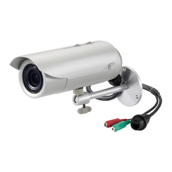
Page 9: Physical Description
Hardware Manual Physical Description Item Description Memory Card Slot Insert a memory card (not included) into this slot for local recording purposes. See How to Install / Remove the Memory Card on page 27 for more information. NOTE: Supports microSDHC and microSDXC cards. Reset Button Use the Reset Button to reset the camera to its factory default settings. - Page 10 Hardware Manual Item Description Digital Input / Output Connects to digital input or output devices, such as an alarm trigger, panic button, etc. Digital Input (DI) and Digital Output (DO) devices are used in applications like motion detection, event triggering, alarm notifications, etc. See How to Connect DI/DO Devices (Optional) on page 23 for information on how to...
-
Page 11: Installation Procedures Using The Bundled Bracket
Hardware Manual Installation Procedures Using the Bundled Bracket Step 1: Install the Bundled Bracket 1. Mark the location of the three (3) screw holes using the bracket plate included in the package. NOTE: Depending on the surface where you will install the camera, it may be necessary to drill the holes and use the supplied screw trox. -
Page 12: Step 2: Attach The Sunshield
Hardware Manual Step 2: Attach the Sunshield The use of sunshield is optional if the camera will be installed indoors. However, if the camera will be installed outdoors, attach the sunshield to protect the lens from all types of weather a screw trox. -
Page 13: Step 3: Install The Camera
Hardware Manual Step 3: Install the Camera 1. If necessary, install a memory card to the camera. See How to Insert the Memory Card on page 27 for more information. 2. Depending on how you want to install the camera, attach the camera to the bracket through one of the two (2) holes below: 3. -
Page 14: Step 4: Waterproof And Connect The Cable
Hardware Manual Step 4: Waterproof and Connect the Cable The camera and the pre-installed network cable, “pigtail”, are resistant to salt, water, weak acid, alcohol, oil, grease and other common solvents. However, users must ensure that the cable connection and the network side cable itself are also protected from different environmental factors. -
Page 15: How To Use The Cable Gland
Hardware Manual How to Use the Cable Gland This section describes how to waterproof the cable-out or “pigtail” of the camera using the bundled cable gland. An exterior-grade Ethernet cable is required. The camera may or may not have to be installed first before doing the cable connections (see related installation procedures for details). - Page 16 Hardware Manual 2. Insert the clamping nut into the Ethernet cable. 3. Insert the sealing insert with claw. 4. Insert the gland body into the Ethernet cable. 5. On the “pigtail” side, insert the washer into the “pigtail”.
- Page 17 Hardware Manual 6. Connect the Ethernet cable connector to the “pigtail” connector. 7. Attach the gland body to the “pigtail”. Make sure the gland body is tightly attached to the “pigtail” and the washer is NOTE: secured between them. 8. Insert the sealing insert into the cable gland body and then attach the clamping nut to complete the cable solution.
-
Page 18: How To Use The Conduit Gland
Hardware Manual How to Use the Conduit Gland This section describes how to waterproof the cable-out or “pigtail” of the camera using the bundled conduit gland and flexible conduit. This is the recommended solution if an exterior-grade Ethernet cable is not available. Before connection, prepare the following materials: Flexible Conduit Conduit Gland... - Page 19 Hardware Manual 2. Pull the Ethernet cable through the flex conduit. Leave enough length of the cable outside the flex conduit. 3. Insert the clamping nut through the flex conduit. 4. Insert the sealing nut and fix it at the end of the flex conduit. 5.
- Page 20 Hardware Manual 6. On the “pigtail” side, insert the washer into the “pigtail”. 7. Connect the Ethernet cable connector to the “pigtail” connector. 8. Attach the gland body to the “pigtail”. Make sure the gland body is tightly attached to the “pigtail” and the washer is NOTE: secured between them.
- Page 21 Hardware Manual 9. Push the flex conduit and insert the sealing nut into the gland body. NOTE: Make sure the clamping nut is tightly attached to the cable gland body and the sealing insert is squeezed tightly. 10. Attach the clamping nut to complete the cable solution.
-
Page 22: Step 5: Connect The Cable
Hardware Manual Step 5: Connect the Cable Connect the other end of the network cable to a switch or injector. Then, connect the switch or injector to a network, PC, and a power source. See Power-over-Ethernet (PoE) connection example below. Network Ethernet Cable Ethernet Cable... -
Page 23: Other Connections
Hardware Manual Other Connections This section describes the procedures in connecting Digital Input and Output (DI/DO) and Audio Input and Output devices. The use of these devices, however, is optional. Audio Input/Output Jacks DI/DO Wires NOTE: If these connectors will not be used, leave the rubber caps on and the wires twisted together to ensure cables remain waterproof and eliminate short-circuit hazards. - Page 24 Hardware Manual Understanding the DI/DO Cables You can connect up to one (1) DI and one (1) DO device to your camera. Digital Input Cables Cable Color Wiring Connection To connect a digital input device, map the Ground Pin (GND) Black digital input device wires to DI (red) and Digital Input (DI)
- Page 25 Hardware Manual Typical Connection Based on these specifications, if the DI device has a voltage of 0V ~ 30V or the DO device has a voltage of < 24V (< 50mA), then the camera can supply internal power to these devices and there is no need to connect the DI/DO device to an external power source.
-
Page 26: How To Connect Audio Input / Output Devices (Optional)
Hardware Manual The illustration below is a graphic example of connecting a relay to a high voltage DO device. 110V-220V AC External Power Source Relay (DO1 Device) Camera Illuminator NOTE: For more information on DI/DO connections, please refer to the Knowledge Base article on our website. -
Page 27: Adjustments And Accessories
Hardware Manual Adjustments and Accessories This section describes the procedures on installing a memory card and resetting the camera. How to Install / Remove the Memory Card The camera supports local video recording or saving of snapshots to a memory card. NOTE: Supports microSDHC and microSDXC cards. -
Page 28: How To Remove The Memory Card
Hardware Manual 3. When done, ensure the rubber seal is aligned and attached to the back cover and then close the back cover by tightening the three (3) screws. CAUTION: Make sure the rubber seal is properly attached and the back cover is closed to ensure water or dust cannot enter the camera. -
Page 29: Adjust The Viewing Angle And Focus
Hardware Manual Adjust the Viewing Angle and Focus The camera already comes pre-focused when taken out of the box. If there is a need to change the viewing angle and focus, follow the steps below to adjust them. 1. Open the front cover. 2. -
Page 30: How To Reset The Camera
Hardware Manual How to Reset the Camera In case there is a need to reset the camera to its default factory settings, do the following procedures while the camera is powered on. 1. Loosen the three (3) screws securing the back cover. NOTE: A cable is connected inside the camera;... -
Page 31: Accessing The Camera
Hardware Manual Accessing the Camera Configure the IP Addresses In order to be able to communicate with the camera from your PC, both the camera and the PC have to be within the same network segment. In most cases, it means that they both should have very similar IP addresses, where only the last number of the IP address is different from each other. - Page 32 Hardware Manual By double-clicking with the left mouse on the camera model, it is possible to automatically launch the default browser of the PC with the IP address of the target camera filled in the address bar of the browser already. If you work with our cameras regularly, then there is even a better way to discover the cameras in the network –...
-
Page 33: Using The Default Camera Ip Address
Hardware Manual Using the Default Camera IP Address If there is no DHCP server in the given network, the user may have to assign the IP addresses to both PC and camera manually to make sure they are in the same network segment. When the camera is plugged into network and it does not detect any DHCP services, it will automatically assign itself a default IP: 192.168.0.100... - Page 34 Hardware Manual Manually adjust the IP addresses of multiple cameras: If there are more than one camera to be used in the same local area network and there is no DHCP server to assign unique IP addresses to each of them, all of the cameras would then have the initial IP address of 192.168.0.100, which is not a proper situation for network devices –...
-
Page 35: Access The Camera
Hardware Manual Access the Camera Now that the camera and the PC are both having their unique IP addresses and are under the same network segment, it is possible to use the Web browser of the PC to access the camera. You can use any of the browsers to access the camera, however, the full functionality is provided only for Microsoft Internet Explorer. - Page 36 Hardware Manual The following examples in this manual are based on Internet Explorer browser in order to cover all functions of the camera. Assuming that the camera’s IP address is 192.168.0.100, you can access it by opening the Web browser and typing the following address into Web browser’s address bar: http://192.168.0.100 Upon successful connection to the camera, the user interface called Web Configurator would appear together with the login page.
- Page 37 To check the firmware version through the Web Configurator, access the Setup page and click System > System Info. For further operations, please refer to the Firmware User Manual.