Table of Contents
Advertisement
Quick Links
Download this manual
See also:
User Manual
IBM System Storage SAN768B-2
Installation, Service, and User Guide
Service information: 2499-816
Read Before Using
This product contains software that is licensed under written license agreements. Your use of such software is subject to
the license agreements under which they are provided.
GA32-0893-00
Advertisement
Table of Contents
Troubleshooting

Related Manuals for IBM SAN768B-2


Summary of Contents for IBM SAN768B-2
- Page 1 IBM System Storage SAN768B-2 Installation, Service, and User Guide Service information: 2499-816 Read Before Using This product contains software that is licensed under written license agreements. Your use of such software is subject to the license agreements under which they are provided.
- Page 3 IBM System Storage SAN768B-2 Installation, Service, and User Guide Service information: 2499-816 GA32-0893-00...
- Page 4 © Copyright IBM Corporation 2011. US Government Users Restricted Rights – Use, duplication or disclosure restricted by GSA ADP Schedule Contract...
-
Page 5: Read This First
Web site: www.redbooks.ibm.com/. For more information about IBM SAN products, see the following Web site: www.ibm.com/servers/storage/san/ For support information for this and other IBM products, see the IBM Support Portal, www.ibm.com/supportportal. Search for the product Machine type or product name. -
Page 6: How To Send Your Comments
Your feedback is important in helping us provide the most accurate and high-quality information. If you have comments or suggestions for improving this document, send us your comments by e-mail to starpubs@us.ibm.com . Be sure to include the following: v Exact publication title... -
Page 7: Table Of Contents
Tables ....xi Chapter 3. Starting and configuring the Safety and environmental notices . . . xiii SAN768B-2 ... . . 31 Safety notices and labels . . xiii Providing power to the SAN768B-2 . - Page 8 Trademarks . . 145 Preparing for a chassis replacement . . 102 Electronic emission notices . . 146 Disconnecting the SAN768B-2 from the network Federal Communications Commission (FCC) and fabric . 105 Class A Statement . . 146 Removing components from the chassis .
- Page 9 Avis de conformité à la réglementation Japan Electronics and Information Technology d'Industrie Canada . 146 Industries Association (JEITA) Statement . . 148 European Union EMC Directive Conformance Korea Communications Commission (KCC) Statement . 146 Class A Statement . . 148 Germany Electromagnetic Compatibility Russia Electromagnetic Interference (EMI) Class Directive .
- Page 10 SAN768B-2 Installation, Service, and User Guide...
-
Page 11: Figures
Figures Port side of the SAN768B-2 (sample Power supply LEDs . . 62 configuration) . Blower assembly LEDs . . 63 Blower (non-port) side of the SAN768B-2 LEDs on the WWN card and bezel . . 65 (sample configuration ) . - Page 12 SAN768B-2 Installation, Service, and User Guide...
-
Page 13: Tables
Critical information checklist example Blades available for the SAN768B-2 . Sample cable routing table for SAN768B-2 Installation tasks, time, and items required Cable routing table for SAN768B-2 (64 ports Items supplied with the 14U rack mount kit shown). . 112 Port and application blades available on the General specifications . - Page 14 SAN768B-2 Installation, Service, and User Guide...
-
Page 15: Safety And Environmental Notices
(D004), at the end of each notice. Use this ID to locate the translation of these danger and caution notices in the IBM System Storage and TotalStorage b-type Directors and Cabinets Safety Notices publication, which is shipped with this product. - Page 16 (D004) A general electrical danger notice provides instructions on how to avoid shock hazards when servicing equipment. Unless instructed otherwise, follow the procedures in the following danger notice. SAN768B-2 Installation, Service, and User Guide...
- Page 17 Electrical voltage and current from power, telephone, and communication cables are hazardous. To avoid a shock hazard: v Connect power to this unit only with the IBM provided power cord. Do not use the IBM provided power cord for any other product.
-
Page 18: Caution Notices
Delivery and subsequent transportation of the equipment The customer should prepare his environment to accept the new product based on the installation planning information provided, with assistance from an IBM Installation Planning Representative (IPR) or IBM authorized service provider. In... - Page 19 Read and comply with the following caution notices before installing or servicing this device. CAUTION: Energy hazard present. Shorting may result in system outage and possible physical injury. Remove all metallic jewelry before servicing. (C001) CAUTION: The weight of this part or unit is more than 55 kg (121.2 lb). It takes specially trained persons, a lifting device, or both to safely lift this part or unit.
-
Page 20: Safety Labels
CAUTION: For CA residents only: IBM recommends installing this product in a room size of 62 cubic meters (2190 cubic feet) or larger at 0.4 ACH ventilation rate to reduce the concentrations of any chemicals emitted by the product. Safety labels As an added precaution, safety labels are often installed directly on products or product components to warn of potential hazards. -
Page 21: Attention Notices
Attention: Many of the field replaceable units (FRUs) are sensitive to electrostatic discharge (ESD), and can potentially be damaged by improper handling. Wear a wrist grounding strap connected to chassis ground (if the SAN768B-2 is plugged in) or a bench ground. Store all ESD-sensitive components in antistatic packaging. -
Page 22: Rack Safety
Attempting to move the drawer partially or completely out of the rack might cause the rack to become unstable or cause the drawer to fall out of the rack. (R001 part 2 of 2) SAN768B-2 Installation, Service, and User Guide... -
Page 23: Rack Relocation (19" Rack)
Rack relocation (19" rack) CAUTION: Removing components from the upper positions in the rack cabinet improves rack stability during relocation. Follow these general guidelines whenever you relocate a populated rack cabinet within a room or building: v Reduce the weight of the rack cabinet by removing equipment starting at the top of the rack cabinet. -
Page 24: Safety Inspections
Internal machine checks Perform the following internal machine checks: 1. Check for any non-IBM changes that might have been made to the machine. If any are present, obtain the “Non-IBM Alteration Attachment Survey” form, number R009, from the IBM branch office. Complete the form and return it to the branch office. -
Page 25: Product Recycling And Disposal
Product recycling and disposal Refer to the IBM Systems Environmental Notices and User Guide (Z125-5823) on the CD shipped with the product for translated environmental statements and information regarding product recycling and disposal. This document may be provided either in printed version or on a documentation CD. See “Removing the batteries”... - Page 26 SAN768B-2 Installation, Service, and User Guide...
-
Page 27: About This Document
The following documents contain information related to this product. The documentation may be printed material, on the documentation CD that is shipped with the product, or available on the web through the IBM Support Portal or IBM Publications Center. v IBM System Storage SAN768B-2 Installation, Service, and User Guide, GA32-0893 (this document, which is also available in accessible HTML format on the documentation CD). -
Page 28: Ibm And Brocade Product Matrix
(FOS) publications, you will notice that the model numbers reflect the corresponding Brocade products. Table 1 provides a product matrix for you to use to correlate the Brocade products and models to the IBM product names and machine types and model numbers. Products withdrawn from marketing are not listed. - Page 29 This product uses standard Microsoft Windows navigation keys. Vendor software The SAN768B includes certain vendor software that is not covered under the IBM license agreement. IBM makes no representation about the accessibility features of these products. Contact the vendor for the accessibility information about its products.
- Page 30 SAN768B-2 Installation, Service, and User Guide...
-
Page 31: Chapter 1. Introduction
This chapter introduces the features and components of the IBM System Storage SAN768B-2 fabric backbone. Throughout the remainder of this document, the product will be referred to as the SAN768B-2, or more generically as system, device, or chassis, where appropriate. This chapter contains the following information: v “Overview of the SAN768B-2”... - Page 32 Diagnostic port (D_Port) functionality. v Fibre Channel over IP (FCIP) functionality through the FX8-24 blade. Attention: This product is not intended to be connected directly or indirectly by any means whatsoever to interfaces of public telecommunications networks. SAN768B-2 Installation, Service, and User Guide...
-
Page 33: Hardware Components
Two slots for control processor blades (CP8): – A single active CP8 blade can control all 384 ports in the chassis. – The standby CP8 blade assumes control of the SAN768B-2 if the active CP fails. v Two slots for core switch blades (CR16-8): –... -
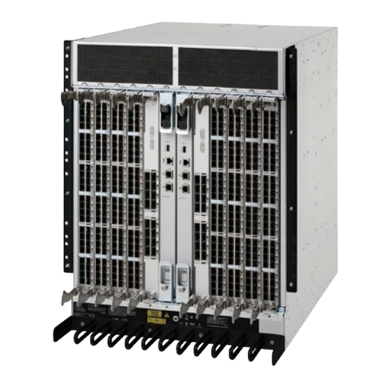
Page 34: Port Side Of The San768B-2
Figure 1. Port side of the SAN768B-2 (sample configuration) Exhaust vent FC16-32 port blade Core switch blade (CR16-8) Cable management comb Control processor blade (CP8) Figure 2 on page 5 shows a sample configuration of the non-port side of the SAN768B-2 with 4 power supplies. -
Page 35: San768B-2 Blades
Figure 2. Blower (non-port) side of the SAN768B-2 (sample configuration ) WWN bezel Blower assembly Power supply SAN768B-2 blades Table 2 summarizes the port, application, control processor, and core switch blades that are available for the SAN768B-2. Table 2. Blades available for the SAN768B-2... - Page 36 Table 2. Blades available for the SAN768B-2 (continued) Description Feature Code Name Function Core switch blade CR16-8 The CR16-8 blade contains the ASICs for switching between port blades. Every port blade connects to every core switch blade. There can be up to...
-
Page 37: High Availability
Nondisruptive "hot" software code loads and activation v Easy configuration, save, and restore The high-availability software architecture of the SAN768B-2 provides a common framework for all applications that reside on the system, allowing global and local status to be maintained through any component failure. High-availability elements consist of the High Availability Manager, the heartbeat, the fault/health framework, the replicated database, initialization, and software upgrade. -
Page 38: Reliability
Reliability The SAN768B-2 uses the following error detection and correction mechanisms to ensure reliability of data: v Error Detection and Correction over main control processor memory v Error Detection and Correction mechanism, which checks for encoder errors and fault isolation (EDFI), such as cyclic redundancy checking (CRC), parity... -
Page 39: Security
v Syslog auditing v RCS (Reliable Commit Service) v NTP v Tasks to manage address assignment, routing, link initialization, fabric initialization, link shutdown, chassis shutdown, and the user interface. Security The list below highlights some of the key security features available for the SAN384B-2 and for other switches running Fabric OS 7.0 or later. -
Page 40: Network Manageability
Network Manageability The SAN768B-2 has a single domain and is managed as a single element with Network Advisor. The SAN768B-2 responds to its own IP address and appears as a separate entity to the Telnet protocol and SNMP. All management interfaces, such as Telnet, Web Tools, standards compliant SMI-S, and Management Server, support a “port N within blade M”... -
Page 41: Chapter 2. Installing And Removing A San768B-2
Switch Cabinet C36. This SAN768B-2 is to be installed and serviced only by qualified IBM service representatives. The SAN768B-2 can be ordered pre-installed in the cabinet, or the SAN768B-2 can be added to an existing C36 cabinet. The cabinet is designed to support a total of two SAN256Bs or SAN768B-2s. The SAN384B chassis can also be installed in the C36 cabinet. -
Page 42: Ordering The Lift Tool
– Routing the cables through the cable channels on the sides of the cabinet – Using patch panels v Ensure that the airflow in the vicinity of the SAN768B-2 is a minimum of 595 cubic meters per hour (350 cubic feet per minute). -
Page 43: Installation Guidelines
1. Provide a space that is 14 rack units (14U) high, 61.29 cm (24.09 in.) deep, and 43.74 cm (17.22 in.). 1U is equal to 4.45 cm (1.75 in.). 2. Plan to install the SAN768B-2 with the non-port side facing the air-intake aisle. The SAN768B-2 can be installed facing either direction, if serviceability and cooling requirements are met. -
Page 44: Installing A San768B-2 In A Cabinet
159.2 kg (351 lb) and requires the specified lift tool to install it. Installing a SAN768B-2 in a cabinet This section describes how to install the SAN768B-2 in the Model C36 cabinet. These procedures use parts that are included in the 14U rack mount kit. Time required Allow approximately 4 hours to complete this procedure. -
Page 45: Tools Required
Note: Assembly instructions for the lift tool are in the shipping container. Tools required You will require the following items to install the SAN768B-2 in the cabinet: v Torque wrench with #2 Phillips screwdriver tip v Flathead screwdriver... - Page 46 1/4-20 x 1/2 in. (1.27 cm) panhead Phillips screw, with lock washer For cabinets that have vertical rails with square holes 10-32 retainer nut 1/4-20 x 1/2 in. (1.27 cm) panhead Phillips screw, with glue 0.375 in. (0.953 cm) alignment washer SAN768B-2 Installation, Service, and User Guide...
-
Page 47: Unpacking The San768B-2
To unpack the SAN768B-2, follow these steps: 1. Cut the bands that encircle the packaging. 2. Remove the lid, the 14U rack mount kit, the accessory kit, and the packing foam from the top of the chassis. -
Page 48: Attaching The Shelf Brackets
For rails with square holes: Use eight screws ( G ) eight alignment washers ( H ) for each bracket, four at each end. Tighten the screws to a torque of 92 cm-kg (80 in.-lb). SAN768B-2 Installation, Service, and User Guide... -
Page 49: Removing The Chassis Door And Cable Management Comb
See Figure 7 on page 22 for approximate positions. Note: Do not align the clip or retainer nuts with the top or bottom holes of the SAN768B-2 mounting brackets because the door will interfere with the screw heads. Attaching clip nuts... -
Page 50: Using The Lift Tool, The 24-Inch Load Plate, And The Bridge Tool
Step 1 on page 21 through step 9 on page 22 describe how to use the lift tool (PN 09P2481) and the 24–inch load plate (PN 11P4369) to install a SAN768B-2 in the cabinet. Step 10 on page 22 through step 23 on page 24 describe how to install the bridge tool (PN 18P5855) in the cabinet for the lower SAN768B-2 or the upper SAN768B-2. - Page 51 SAN768B-2 to reduce the weight. This can reduce the weight by up to 27 kg (60 lb). 4. Move the lift tool next to the pallet that contains the SAN768B-2. a. Adjust the load platform to the same height.
-
Page 52: Chassis Installation From Rear (Exhaust Aisle Side) Of The Cabinet
Raise the platform to allow enough room to attach the anti-tip bracket. d. Secure the anti-tip bars by using the anti-tip bracket and bolt. 10. If you are installing the lower SAN768B-2, go to step 11. If you are installing the upper SAN768B-2, go to step 12 on page 23. -
Page 53: Locking The Shelf Into Position
Note: The shelf in the picture below is shown with a different director. Figure 8. Locking the shelf into position 12. For the upper SAN768B-2, install the bridge tool by completing the following steps: a. Remove the bridge tool from the box and adjust the two supports 45°. -
Page 54: Attaching The Port Side Of The Chassis To The Cabinet Rails
15. Remove the retention straps. 16. Slide the SAN768B-2 into the cabinet until it rests securely on the shelf brackets. 17. Remove the wheel chocks, release the wheel brake, and move the lift tool away from the cabinet. 18. Uninstall the bridge tool and return it to its original box. -
Page 55: Aligning The Chassis Door With The Ball Studs On The Chassis
Figure 10. Aligning the chassis door with the ball studs on the chassis Chapter 2. Installing and removing a SAN768B-2... -
Page 56: Port Numbering
Note: For turning on the power and for the configuration instructions, see Chapter 3, “Starting and configuring the SAN768B-2,” on page 31. Attention: Do not connect the SAN768B-2 to the network until the IP addresses are correctly set. Port numbering Table 5 has a list of available port blades for the SAN768B-2. -
Page 57: Chassis Slots
Slots are numbered 1 through 12, from left to right when facing the port side of the SAN768B-2. Control processor blades (CP8) can be installed only in slots 6 and 7. Core switch blades (CR16-8) can be installed only in slots 5 and 8. Port or application blades can be installed in slots 1–4 and 9–12. -
Page 58: Cable Design For The Msfp Patch Cables For The Fc8-64 High Density Port Blade
FC8-64 port blade. Narrower OM-3 LC cables are used to connect the FC8-64. These cables are offered by several major manufacturers. Contact your IBM representative for options regarding different cable and patch panel configurations to simplify cable management with higher density FC8-64 port blades. -
Page 59: Removing A San768B-2 From The Cabinet
Removing a SAN768B-2 from the cabinet If you need to remove a SAN768B-2 chassis from a cabinet to move it to a new location, follow the instructions below to remove the chassis, and then follow the installation instructions (“Installing a SAN768B-2 in a cabinet”... - Page 60 A pinch point exists between the load plate and the bridge tool. P/N 18P5850-B SJ000752 14. Slide the SAN768B-2 from the cabinet onto the 24–inch load plate. Center the SAN768B-2 on the platform. 15. Install the retention straps. 16. Remove the wheel chocks, release the wheel brake, and move the lift tool away from the cabinet.
-
Page 61: Chapter 3. Starting And Configuring The San768B-2
On the displayed product page, click the Interoperability Matrix link in the Learn more section. The SAN768B-2 must be configured before it is connected to the fabric, and all of the configuration commands must be entered through the active CP blade. The... -
Page 62: Flow Of Basic Configuration Tasks
2. Specify a switch name. See “Customize a switch name” on page 36. 3. Specify a domain ID for the SAN768B-2. See “Setting the Domain ID” on page 4. Verify the PID mode and connect the SAN768B-2 to the fabric. See “Verifying the PID mode”... -
Page 63: Providing Power To The San768B-2
Establishing a serial connection and logging on to the SAN768B-2 To establish a serial connection and log on to the SAN768B-2: 1. Verify that the SAN768B-2 is powered on and that POST is complete by verifying that all power LED indicators on the port, control processor, and core switch blades display a steady green light. -
Page 64: Logging In To The Serial Console Port
To log in to the SAN768B-2 through the serial connection, follow these steps. 1. Log in to the SAN768B-2 as admin. The default password is "password." At the initial login, you are prompted to change the default passwords. Record the new passwords and keep this information in a secure location. -
Page 65: Logging Off The Serial Console Port And Disconnecting The Serial Cable
2. Set up the SAN768B-2 IP address by entering the ipaddrset -chassis command at the prompt. swDir:admin> ipaddrset -chassis Enter the information at the prompts. Specify the -chassis IP address. The -sw 0 IP address is not valid on this chassis. -
Page 66: Establishing An Ethernet Connection
Customize a switch name The switch name of the SAN768B-2 can be up to 30 characters long; can include letters, numbers, and underscore characters; and must begin with a letter. Note: Changing the name causes a domain address format RSCN to be issued. -
Page 67: Setting The Domain Id
Setting the date To set the date, follow these steps. 1. If necessary, log on to the SAN768B-2 by Telnet, using the admin account. The default password is password. 2. Enter the date command, using the following syntax:date "mmddHHMMyy"... -
Page 68: Synchronizing Local Time
The principal or primary FCS switch synchronizes its time with the NTP server every 64 seconds. switch:admin> tsclockserver LOCL switch:admin> tsclockserver "132.163.135.131" switch:admin> tsclockserver 132.163.135.131 switch:admin> The following example shows how to set up more than one NTP server using a DNS name: SAN768B-2 Installation, Service, and User Guide... -
Page 69: Verifying The Pid Mode
Verifying the PID mode Before connecting the SAN768B-2 to the fabric, verify that the port identifier (PID) mode on the SAN768B-2 matches the other switches in the fabric. This parameter must be set identically on all switches in the fabric. This parameter is set using the configure command. - Page 70 Follow these steps to install the QSFPs and cables in the 16 Gbps core blades. These transceivers and cables are used to form the inter-chassis links (ICL) with neighboring SAN768B-2 and SAN384B-2 backbones. The transceivers should be installed in the blades before connecting the cables. Because each QSFP contains four 16 Gbps ports, be aware that any problems with one port could affect all four ports in the quad if the QSFP has to be replaced.
- Page 71 SAN384B-2 with a core blade installed in slot 3. Some details for the SAN768B-2 will be different (such as the slot numbers) , but the reported information for the QSFPs will be similar. Note that the State reported for an unconnected QSFP (shown QSFP 0 and Ports 0-3 below) is No_SigDet.
-
Page 72: Managing Cables
This command provides information about switch and port status. 4. Verify the correct operation of the SAN768B-2 in the fabric by entering the fabricShow command from the workstation. This command provides general information about the fabric. -
Page 73: Fabric Os Firmware Updates
Select the SAN768B-2 and SAN384B-2 product link v On the displayed product page, click the Interoperability Matrix link in the Learn more section. Firmware release notes and download files are available through the IBM Support Portal. To view release notes and to download firmware: v Go to the IBM Support Portal www.ibm.com/supportportal. -
Page 74: Powering Off The San768B-2
2. Power off the chassis by flipping the AC power switches on the power supplies to "O". The LEDs inside AC power switches should turn off. To maintain the ground connections, leave the power cords connected to the power supplies and to the electrical outlets. SAN768B-2 Installation, Service, and User Guide... -
Page 75: Chapter 4. Monitoring System Components
SAN768B-2. These commands are switchShow and chassisShow. Examples of these commands are shown below. Note in the switchShow command the new switchType for the SAN768B-2 as well as the 16 Gbps speed identification for capable ports. The output has been truncated to reduce information duplication. - Page 76 No_Module FC 78a280 No_Module FC 78a380 No_Module FC 78a480 No_Module FC 78a580 No_Module FC 78a680 No_Module FC 78a780 No_Module FC 782080 No_Light FC 782180 No_Module FC 782280 No_Module FC 782380 No_Light FC 782480 No_Module FC SAN768B-2 Installation, Service, and User Guide...
- Page 77 782580 No_Module FC 782680 No_Module FC 782780 No_Light FC 782880 No_Module FC 782980 No_Module FC 782a80 No_Module FC 782b80 No_Module FC 782c80 No_Module FC 782d80 No_Module FC 782e80 No_Module FC 782f80 No_Module FC 783000 No_Light FC 783100 No_Light FC 783200 No_Light FC 783300 No_Light FC...
- Page 78 No_Module FC <output truncated> SAN768B-2_8 :root> Note with the chassisShow command, the Chassis Family designation for the SAN768B-2 along with specific information about every field-replaceable unit in the chassis is displayed. SAN768B-2_8:root> chassisshow Chassis Family: SAN768B-2 Chassis Backplane Revision: 0...
- Page 79 Update: Day: 27 Month: 9 Year: 2011 Time Alive: 45 days Time Awake: 0 days SW BLADE Slot: 3 Header Version: 2 Power Consume Factor: -130 Factory Part Num: 60-0000071-07 Factory Serial Num: BAH0344E01G Manufacture: Day: 2 Month: 11 Year: 2010 Update: Day: 7 Month: 4 Year: 2011 Time Alive: 280 days Time Awake: 0 days...
- Page 80 Manufacture: Day: 29 Month: 12 Year: 2010 Update: Day: 28 Month: 3 Year: 2011 Time Alive: 319 days Time Awake: 0 days FAN Unit: 3 Header Version: 2 Power Consume Factor: -126 Factory Part Num: 60-1000384-09 Factory Serial Num: AGB0652E0H8 SAN768B-2 Installation, Service, and User Guide...
-
Page 81: Port Or Application Blade Status
Manufacture: Day: 29 Month: 12 Year: 2010 Update: Day: 28 Month: 3 Year: 2011 Time Alive: 319 days Time Awake: 0 days WWN Unit: 1 Header Version: 2 Power Consume Factor: -1 Factory Part Num: 60-1000491-05 Factory Serial Num: AFX0602F001 Manufacture: Day: 29 Month: 12 Year: 2010 Update: Day: 28 Month: 3 Year: 2011 Time Alive: 319 days... -
Page 82: Fc16-32 Port Blade
Figure 14. FC16-32 port blade Power LED Fibre Channel port Status LED Port status LED SAN768B-2 Installation, Service, and User Guide... - Page 83 Figure 15. FC16-48 port blade Power LED Fibre Channel port Status LED Port status LED Chapter 4. Monitoring system components...
-
Page 84: Fc8-64 Port Blade
Figure 16. FC8-64 port blade Status LED Fibre Channel port Power LED Port status LED Note: The FC8-64 port blade requires narrower OM-3 LC cables. SAN768B-2 Installation, Service, and User Guide... - Page 85 Figure 17. FX8-24 extension blade Power LED GbE port 6 LED Port map Status LED 10 GbE port 0 GbE port 6 10 GbE port 0 LED Chapter 4. Monitoring system components...
-
Page 86: Port And Application Blade Led Descriptions
2 seconds) is faulty. the LED continues to flash, replace the blade. Fast-flashing amber (on 1/2 Environmental range exceeded. Check for out-of-bounds second, then off 1/2 second) environmental condition and correct it. SAN768B-2 Installation, Service, and User Guide... -
Page 87: Control Processor Blade (Cp8) Status
Slow-flashing green (on 1 Port is online but segmented, Verify that the correct device is second, then off 1 second) indicating a loopback plug or attached to the SAN768B-2. cable or an incompatible switch. Fast-flashing green (on 1/4 Port is in internal loopback No action required. -
Page 88: Control Processor Blade (Cp8) Components
Figure 18 identifies the control processor blade (CP8) and its components. Figure 18. Control processor blade (CP8) components Power LED Console port (10101) Status LED Ethernet port (MGMT IP) USB LED Ethernet port (SERVICE IP) USB port Active CP LED SAN768B-2 Installation, Service, and User Guide... -
Page 89: Core Switch Blade (Cr16-8) Status
If LED remains amber, contact IBM. Slow-flashing amber CP blade is not Pull blade out and (on 2 seconds; then seated correctly or is reseat it. If LED off 2 seconds) faulty. -
Page 90: Core Switch Blade (Cr16-8), Leds And Qsfp Connectors
LED purpose Color Status Action Power Steady green CR16-8 blade is on No action required. No light (LED is off) CR16-8 blade is not Ensure that the blade is firmly seated and has power. SAN768B-2 Installation, Service, and User Guide... -
Page 91: Power Supply Status
2. Check the power supply status by entering psShow. The power supply status displays OK, Absent, or Faulty. If a power supply displays absent or faulty, contact IBM. Both physically absent or faulty could also be the result of the power supply not being properly seated or being turned off. -
Page 92: Blower Assembly Status
If a blower assembly is absent or faulty, contact IBM. Both physically absent or faulty could also be the result of the blower assembly not being properly seated or being turned off. -
Page 93: Blower Assembly Leds
Figure 21. Blower assembly LEDs Item Description Power LED Fault LED Table 10. Blower assembly LED descriptions Recommended LED purpose Color Status action Power No Light (LED is off) Blower assembly Ensure that the does not have power. blower assembly is firmly seated and has power. -
Page 94: Wwn Bezel And Wwn Card Status
EM-HIL_FAIL, 2, HIL Error: hilSetFruHistory failed, rc=-3 for SLOT 2. Check the LED indicators on the WWN bezel and verify that they reflect the actual status of the components. The WWN bezel covers the WWN cards and SAN768B-2 Installation, Service, and User Guide... -
Page 95: Leds On The Wwn Card And Bezel
allows its LEDs to shine through (see Figure 22). The LEDs on the WWN bezel provide a consolidated view of the port, CP, and CR blade status (see Table 12). Table 12. WWN LED patterns Recommended location/purpose Color Status action Port blade/CP/CR Steady green . - Page 96 SAN768B-2 Installation, Service, and User Guide...
-
Page 97: Chapter 5. Removing And Installing Components
Attention: Read the safety notices before servicing (see “Safety notices and labels” on page xiii). The field replaceable units (FRUs) in the SAN768B-2 can be removed and installed without special tools. The SAN768B-2 can continue operating during many of the FRU replacements if the conditions specified in the procedure are followed. -
Page 98: Removing And Installing A Cable Management Comb
See Figure 23. 2. Push the door into place. It will snap onto the studs. Removing and installing a cable management comb The SAN768B-2 can continue to operate during the replacement of the cable management comb. Time and items required The replacement procedure for the cable management comb takes less than 5 minutes. -
Page 99: Installing A Cable Management Comb
2. Remove the cables from the cable management comb and rearrange the cables around the comb. 3. Unscrew and save the four screws holding the comb to the chassis (see Figure 24). Support the comb to prevent it from falling. 4. -
Page 100: Time And Items Required
Slots are numbered from 1 through 12, from left to right when facing the port side of the SAN768B-2. Port and application blades can be installed in slots 1 through 4 and 9 through 12. Time and items required The installation procedure for each blade takes 5 to 25 minutes, depending on the number of ports, transceivers, and cables involved. -
Page 101: Installing A Blade
7. Disconnect all cables and transceivers from the blade. For mSFP transceivers (FC8-64 only), it is recommended that you use the pull tab to remove the transceiver from the blade before removing the cable from the transceiver. 8. Unscrew the two thumbscrews from the top and bottom ejectors on the blade (see Figure 25) using the Phillips screwdriver. -
Page 102: Removing And Installing Blade Filler Panels
1. Remove the chassis door. 2. Unscrew the thumb screws on the panel using a Phillips screwdriver. 3. Using the tabs, pull the filler panel out of the chassis. (See Figure 26 on page 73.) SAN768B-2 Installation, Service, and User Guide... -
Page 103: Installing A Filler Panel
Removing and installing a CP8 control processor blade This section describes how to remove and install a control processor (CP8) blade. Each SAN768B-2 has two CP8 blades located in slot 6 and slot 7. Attention: The firmware upgrade policy for CP8 blades specifies testing for the current Fabric OS release and one version earlier. -
Page 104: Time And Items Required
ESD (electrostatic discharge) grounding strap v Workstation computer v Serial cable v IP address of an FTP server for backing up the SAN768B-2 configuration v #2 Phillips screwdriver v Replacement control processor (CP8) blade. Attention: If you are upgrading through multiple versions of the Fabric OS, refer to Table 13 on page 79, to see which intermediate versions of the Fabric OS you will need. -
Page 105: Recording Critical San768B-2 Information
Recording critical SAN768B-2 information Back up the SAN768B-2 configuration before you replace a CP blade. Refer to the Fabric OS Administrator’s Guide for backup information. 1. Connect to the chassis and log in as admin, using a serial console connection. -
Page 106: Removing A Control Processor Blade (Cp8)
Removing a control processor blade (CP8) The SAN768B-2 continues to operate while a CP blade is being installed if the redundant CP blade is active and a failover does not occur. You can prevent failover by entering the haDisable command. -
Page 107: Installing A Control Processor Blade (Cp8)
Figure 27. Removing the control processor (CP8) blade Installing a control processor blade (CP8) Attention: Read ALL of the instructions for replacing the CP blade before beginning the procedure. Use the same version of Fabric OS on both CP blades. Using different versions is not supported and may cause malfunctioning. -
Page 108: Verifying Operation Of The New Cp Blade
CP blade is connected, issue the firmwareShow command there. More information is available through the console. Attention: The SAN768B-2 requires Fabric OS 7.0.0 or later to be recognized. If the firmware on the replacement blade is earlier than 7.0.0 it must be brought up to the version on the active CP blade, which must be at least 7.0.0. -
Page 109: Downloading Firmware From An Ftp Server
All packages have been downloaded successfully. Relocating an internal firmware image on the CP blade. 2011/05/24-11:07:22, [SULB-1032], 7260, SLOT 7 | CHASSIS, WARNING, SAN768B-2, Relocating an internal firmware image on the CP. net boot... The internal firmware image is relocated successfully. - Page 110 From the Release notes page, click the Release Firmware link and follow the online prompts to navigate to the Brocade Downloads for IBM End Users page. f. Follow the instructions on the Brocade pages. Enter all requested information (use default values).
-
Page 111: Downloading Firmware From A Usb Drive
Firmware is being downloaded to the switch. This step may take up to 30 minutes. Preparing for firmwaredownload... 2011/05/24-10:59:39, [SULB-1001], 7258, SLOT 7 | CHASSIS, WARNING, SAN768B-2, Firmwaredownload command has started. 2011/05/24-10:59:39, [SULB-1036], 7259, SLOT 7 | CHASSIS, INFO, SAN768B-2, The current Version: Fabric OS v7.0.0 Start to install packages... - Page 112 All packages have been downloaded successfully. Relocating an internal firmware image on the CP blade. 2011/05/24-11:07:22, [SULB-1032], 7260, SLOT 7 | CHASSIS, WARNING, SAN768B-2, Relocating an internal firmware image on the CP. net boot... The internal firmware image is relocated successfully.
-
Page 113: Completing The Cp8 Blade Replacement
Removing and installing a core switch blade (CR16-8) This section describes how to remove and install a core switch blade. Each SAN768B-2 has two core switch blades: one in slot 5 and one in slot 8. SeeFigure 28 on page 85. -
Page 114: Time And Items Required
For more information about error messages, refer to the Fabric OS Message Reference. Removing a core switch blade (CR16-8) The SAN768B-2 continues to operate while a core switch blade is being replaced. Attention: Follow ESD precautions (“ESD precautions” on page xix). Note: The CR16-8 blade is compatible only with the SAN768B-2 Complete the following steps to remove a CR blade. -
Page 115: Installing A Core Switch Blade (Cr16-8)
Installing a core switch blade (CR16-8) Attention: Follow ESD precautions (“ESD precautions” on page xix). Note: The CR16-8 blade is compatible only with the SAN768B-2. Complete the following steps to install a CR16-8 core switch blade. 1. Open the ejectors by rotating them toward the center of the blade face. Orient the CR blade so that the handles are toward you and the flat metal side is on your left. -
Page 116: Removing And Installing A Power Supply
Removing a power supply Complete the following steps to remove a power supply. 1. If the SAN768B-2 will not be operating during the replacement procedure, go to step 2. SAN768B-2 Installation, Service, and User Guide... -
Page 117: Installing A Power Supply
If the SAN768B-2 will continue operating during the replacement, check the power LEDs to verify that the minimum number of power supplies is functioning. See “Power specifications” on page 127 to determine your power requirements. 2. Turn off the power switch. -
Page 118: Removing And Installing A Blower Assembly
Removing and installing a blower assembly Use this procedure for removing and installing a blower assembly. Attention: The SAN768B-2 can continue operating during the replacement of one blower assembly if the other two blower assemblies are operating, To ensure continuous adequate cooling, maintain all three operating blower assemblies at all times except for the brief period when replacing a blower assembly. -
Page 119: Installing A Blower Assembly
Figure 31. Removal and replacement of the blower assembly Installing a blower assembly Complete these steps to install a blower assembly. 1. Orient the blower assembly and slide it into the chassis, pushing firmly to ensure that it is seated. 2. -
Page 120: Verifying The Need For Replacement
Complete these steps to remove the WWN bezel and WWN card. Attention: Follow ESD precautions (see “ESD precautions” on page xix). 1. Open a Telnet session to the SAN768B-2 and log in to the active CP as admin. The default password is password. -
Page 121: Installing The Wwn Bezel And Wwn Card
7. Remove the screws from the WWN bezel (see Figure 32). Pull the bezel away from chassis and set it aside. The WWN cards are visible. 8. Use a Phillips screwdriver to unscrew the two screws which secure the WWN card to the chassis. -
Page 122: Removing And Installing Transceivers
Optical transceiver extraction tool (for SFP+ transceivers) Removing and installing an SFP+ optical transceiver The SAN768B-2 comes with a transceiver extraction tool (see Figure 33 on page 93) and holster. The extraction tool is designed to remove transceivers with wire bails from blades where the space is limited. -
Page 123: Optical Transceiver (Sfp+) Extraction Tool
Figure 33. Optical transceiver (SFP+) extraction tool Note: This tool is part of the SAN768B-2 ship group and should be kept with the chassis. Attention: mSFP optical transceivers should not be inserted into ports intended for SFP+ transceivers. They will be faulted on power-up. -
Page 124: Removing And Installing An Msfp Optical Transceiver
Note: The mSFP transceivers are used only with the FC8-64 port blade. Narrower OM-3 LC cables are used to connect the FC8-64. These cables are offered by several major manufacturers. Contact your IBM representative for options regarding different cable and patch panel configurations to simplify cable management with higher density FC8-64 port blades. -
Page 125: Removing And Replacing Inter-Chassis Link (Qsfp) Cables
An ICL license must be installed on all systems forming the ICL connection. The systems can be any combination of up to five neighboring SAN384B-2 and SAN768B-2 chassis. An off-the-shelf QSFP cable up to 50 meters long can be used as an ICL cable. -
Page 126: Icl Connector Port Leds
Figure 38 on page 99 shows an acceptable cabling configuration for the ICL feature. The recommended topology is the parallel type where there are four QSFP cables connected between any pair of SAN384B-2 or SAN768B-2 chassis. The full mesh configuration is also supported. -
Page 127: Time And Items Required
Figure 37. QSFP cable and transceiver Time and items required The replacement procedure for an QSFP cable takes less than five minutes. You will need a replacement QSFP cable and transceiver (if necessary). Removing an inter-chassis link (QSFP) cable To remove an inter-chassis link (QSFP) cable, complete these steps. 1. -
Page 128: Possible Icl Configurations
The following figure illustrates one possible QSFP cable configuration between two SAN384B-2 or SAN768B-2 chassis. Up to five neighboring chassis can be connected as long as each of two cores in one chassis is interconnected with each of two cores in the next chassis. -
Page 129: Qsfp Cable Connections-Sample Configuration
Figure 38. QSFP cable connections–sample configuration, parallel type Chassis 1 Chassis 2 Chapter 5. Removing and installing components... -
Page 130: Removing The Batteries
Repair or disassemble Exchange only with the IBM-approved part. Recycle or discard the battery as instructed by local regulations. In the United States, IBM has a process for the collection of this battery. For information, call 1-800-426-4333. Have the IBM part number for the battery unit available when you call. -
Page 131: Removing And Replacing The Chassis
The SAN768B-2 must be removed from the fabric and powered off to perform this procedure. Contact IBM if you have any questions about whether the SAN768B-2 chassis requires replacement. -
Page 132: Verifying Necessity Of Replacement
Note: The SAN768B-2 must be removed from the fabric and powered off to perform this procedure. Contact IBM Support if you have any questions about whether the chassis requires replacement. Verifying necessity of replacement Before replacing the chassis, verify that the replacement is necessary. Ensure that the components are firmly seated when troubleshooting. -
Page 133: Critical Information Checklist Example
New serial number (if available): Complete the following steps to record critical switch and SAN information: 1. Open a Telnet session and login to the SAN768B-2 as admin. The default password is password. Refer to your records for current passwords. Enable the logging function on your Telnet or serial console connection. - Page 134 Alternatively, you can save the configuration file to the USB device. 3. Record the SAN768B-2 values on a workstation, following steps 4 through 9 on page 105 below. 4. Record the WWN value: Enter wwn, then copy the command output into a file named configmiscinfo.txt.
-
Page 135: Disconnecting The San768B-2 From The Network And Fabric
-qsfp v fabricShow Copy the command output into a text file named SANbefor.txt. After the SAN768B-2 is restored to the fabric, this information can be used to verify that no unintentional changes have occurred to the fabric. switch:admin> nsshow Enter Pid COS PortName NodeName TTL <output truncated>... -
Page 136: Removing Components From The Chassis
Although the empty chassis is lighter than a fully populated chassis, a lifting device is still required to move it. Refer to “Removing a SAN768B-2 from the cabinet” on page 29 for more detailed instructions on removing a SAN768B-2 from a cabinet. -
Page 137: Installing Components Into The New Chassis
(C011) 32-55 kg (70.5-121.2 lbs) Attention: Do not place a SAN768B-2 chassis directly on the floor. It cannot be easily moved from the floor back onto a lift or pallet. 1. Uninstall the chassis from the cabinet (see “Removing a SAN768B-2 from the cabinet”... -
Page 138: Downloading The Configuration
11. Power-on the chassis “Providing power to the SAN768B-2” on page 33. The system performs a power-on self-test (POST). The POST takes a minimum of three minutes and is complete when LED activity returns to standard state. 12. Verify that the POST is complete. All power LED indicators on the port, control processor, and core switch blades should be a steady green. - Page 139 SW BLADE FC16-48 ENABLED SW BLADE FC8-64 ENABLED switch:admin> 3. Verify that the SAN768B-2 is functioning correctly by entering switchShow or switchStatusShow. The switchShow command displays chassis and port status information. switch:admin> switchshow switch:FID128:root> switchshow switchName: SAN768B-2_8 switchType: 120.1 switchState: Online...
-
Page 140: Reconnecting The System To The Network And Fabric
Connect the other ends to an Ethernet 10/100/1000 Base-T LAN, if not already connected. Note: The SAN768B-2 can be accessed by remote connection using any of the available management tools, such as Telnet or Web Tools. Ensure that the SAN768B-2 is not modified from other connections during the rest of this procedure. -
Page 141: Cable Routing Tables
3. Resolve any issues or unintentional changes to the SAN768B-2 or fabric. v If there are any mechanical problems, try reseating the associated component. v If the configuration information is not correct for the SAN768B-2, modify as required. v If other issues exist, contact technical support. -
Page 142: Cable Routing Table For San768B-2 (64 Ports Shown)
Work 5 - 2 Workstation 5 Com 2 Serial Slot 8 Port 15 North 24 - 8/15 RAID 16 - 4 RAID 16 Table 17. Cable routing table for SAN768B-2 (64 ports shown) Slot/Port Cable labels Connected Slot/Port of Slot Port Switch end... - Page 143 Table 17. Cable routing table for SAN768B-2 (64 ports shown) (continued) Slot/Port Cable labels Connected Slot/Port of Slot Port Switch end Device end device device Chapter 5. Removing and installing components...
- Page 144 SAN768B-2 Installation, Service, and User Guide...
-
Page 145: Chapter 6. Installing New Features
Refer to “Safety notices and labels” on page xiii before performing any service or installation procedures. The SAN768B-2 can be upgraded with any of the following hot-pluggable features while the SAN768B-2 is operational. Refer to the individual feature installation instructions for any possible exceptions. -
Page 146: Procedures
8. Verify the installation. For information about how to check the status of hardware components using the CLI, see the Fabric OS Administrator's Guide, which is located on the product documentation CD. SAN768B-2 Installation, Service, and User Guide... -
Page 147: Fc3864 - Installing An 8-Gb 64-Port Port Blade
Disassembling any part of a port blade voids the part warranty and regulatory certifications. There are no user-serviceable parts inside the port blade. These instructions cover installing a new FC3864 in the SAN768B-2 chassis. Time required 20 minutes or more per port blade due to port and cable density... - Page 148 FC8-64 port blade. Narrower OM-3 LC cables are used to connect the FC8-64. These cables are offered by several major manufacturers. Contact your IBM representative for options regarding different cable and patch panel configurations to simplify cable management with higher density FC8-64 port blades.
-
Page 149: Fc3890 - Installing An Fx8-24 Extension Blade
FC3890 - Installing an FX8-24 extension blade This feature can be installed while the SAN768B-2 is operational. Attention: Follow these precautions for all procedures in this section to avoid damaging the port blades or chassis: v Wear a grounded ESD strap when handling a port blade (see “ESD precautions”... -
Page 150: Fc7871 - Installing A Qsfp And Inter-Chassis License
11. Reinstall the chassis door. See “Removing and installing the chassis door” on page 67. FC7871 - Installing a QSFP and inter-chassis license This feature can be installed while the SAN768B-2 is operational. Time required Less than 10 minutes, not including installation of the ICL license or any needed configuration. - Page 151 7. Install the chassis door (“Removing and installing the chassis door” on page 67). 8. Enable the inter-chassis links. See the iclCfg section in the Fabric OS Command Reference Manual for CLI command options. 9. Verify the operation of the ICL (see Table 14 on page 96). 10.
- Page 152 SAN768B-2 Installation, Service, and User Guide...
-
Page 153: Appendix A. Product Specifications
Appendix A. Product specifications This appendix provides product specifications for the SAN768B-2 for the following: v “General specifications” v “System architecture” v “System size and weight” on page 126 v “Facility requirements” on page 126 v “Power specifications” on page 127 v “Environmental requirements”... - Page 154 Media types Note: For a listing of transceivers compatible with this product: v Go to the IBM SAN web page www.ibm.com/ systems/storage/san v Select the SAN768B-2 product link v On the SAN768B-2 product page, click the Interoperability Matrix link.
- Page 155 Table 19. System architecture (continued) Fabric services Advanced Performance Monitoring; Adaptive Networking (Ingress Rate Limiting, Traffic Isolation, QoS); auditing; BB credit recovery; Advanced Zoning (default zoning, port/WWN zoning, broadcast zoning); Dynamic Path Selection (DPS); End-to-End Performance monitoring; Extended Fabrics; Fabric Watch; FDMI;Frame Redirection;...
-
Page 156: System Size And Weight
Chassis door 2.09 kg (4.6 lb.) Facility requirements The facility where the SAN768B-2 is in use must meet the following requirements to provide for correct operation: v Adequate supply circuit, line fusing, and wire size, as specified by the electrical... -
Page 157: Power Specifications
The power specifications listed in Table 22 v The environmental specifications listed in Table 23 on page 128 v If the SAN768B-2 will be installed in an EIA rack, ensure the following: – All equipment installed in the rack has a reliable branch circuit ground connection, and does not rely on a connection to a branch circuit, such as a power strip. -
Page 158: Environmental Requirements
Fibre channel port specifications The Fibre channel ports in the SAN768B-2 support full duplex link speeds at 2, 4, 8, 10, or 16 Gbps inbound and outbound, automatically negotiating to the highest common speed of all devices connected to the port. -
Page 159: Data Transmission Ranges
(Feature Code 7880). See the IBM TotalStorage SAN Cabinet 2109 Model C36 Installation and Service Guide for information on connecting the cabinet to the facility power source. If the stand-alone feature is ordered for the SAN768B-2, then Appendix A. Product specifications... - Page 160 Contact your IBM representative for more information on these power cords. SAN768B-2 Installation, Service, and User Guide...
-
Page 161: Appendix B. Application Blades
– Four per trunk through the GbE ports – Ten per trunk through the 10 GbE ports v SO-TCP with reorder resistance v FastWrite over FCIP v Tape pipelining over FCIP v Virtual E_ports v FCIP QoS © Copyright IBM Corp. 2011... - Page 162 Up to three FC trunking groups. The three groups are defined as: – Trunk group 0: FC ports 0, 1 – Trunk group 1: FC ports 6, 7 – Trunk group 2: FC ports 2, 3, 4, 5, 8, 9, 10, 11 SAN768B-2 Installation, Service, and User Guide...
-
Page 163: Appendix C. Diagnostics And Troubleshooting
Fabric Manager, Web Tools, Fabric Watch, and Advanced Performance Monitoring. If the SAN768B-2 does not operate as expected, the following steps can be taken to diagnose the problem: v Check the LEDs and refer to the LED tables (see Chapter 4, “Monitoring system components,”... -
Page 164: Interpreting Post And Boot Results
If one or more LEDs do not return to a normal state, and this is not due to the SAN768B-2 being set to beacon, refer to the relevant LED table to identify and correct the problem. For port blades, CP blades, and core switch blades, the slotShow command can be used to check the status of the slots. -
Page 165: Boot
1. Universal port configuration is performed. 2. Links are initialized. 3. Fabric is analyzed. If any ports are connected to other switches, the SAN768B-2 participates in a fabric configuration. 4. The SAN768B-2 obtains a domain ID and assigns port addresses. - Page 166 9600 bits per second, 8 databits, no parity, 1 stop bit, no flow control. Serial port might be incompatible Ensure that the SAN768B-2 is connected to an (only RS–232 is supported). RS–232 port. RS–423 serial ports might experience difficulties due to corner-case incompatibilities of the standards.
- Page 167 Table 26. Troubleshooting (continued) None of the LEDs on an Component might not be seated Ensure that the SAN768B-2 has power and individual component are correctly. component is firmly seated. If problem continues, run the sensorShow command to determine component status. If component is a CP blade or port blade, enter the slotShow command to determine status.
- Page 168 SAN768B-2 Installation, Service, and User Guide...
-
Page 169: Appendix D. Blade Port Numbering
Appendix D. Blade port numbering The illustrations in this appendix show the port numbering for the different SAN768B-2 blades. See “Port numbering” on page 26 for details on the port numbering pattern for the different blades. v Figure 40 shows an FC16-32 port blade... - Page 170 FC ports 16-31 (bottom to top) Status LED FC ports 0-15 (bottom to top) Figure 41. FC16-48 port blade Power LED FC ports 24-47 (bottom to top) Status LED FC ports 0-23 (bottom to top) SAN768B-2 Installation, Service, and User Guide...
-
Page 171: Fc8-64 Port Blade
Figure 42. FC8-64 port blade Power LED Port 61 LED Status LED Port 29 LED Port 63 FC ports 32-63 (bottom to top) Port 30 FC ports 0-31 (bottom to top) Appendix D. Blade port numbering... - Page 172 FC ports 0-5 (numbered bottom to top) Power LED FC ports 6-11 (numbered bottom to top) 1 GbE ports 0-3 (numbered bottom to top) 1 GbE ports 4-9 (numbered bottom to top) 10 GbE ports 0-1 (numbered bottom to top) SAN768B-2 Installation, Service, and User Guide...
-
Page 173: Notices
The materials at those web sites are not part of the materials for this IBM product and use of those web sites is at your own risk. - Page 174 Information concerning non-IBM products was obtained from the suppliers of those products, their published announcements or other publicly available sources. IBM has not tested those products and cannot confirm the accuracy of performance, compatibility or any other claims related to non-IBM products.
-
Page 175: Trademarks
International Business Machines Corporation in the United States, other countries, or both. A complete and current list of other IBM trademarks is available on the Web at www.ibm.com/legal/copytrade.shtml Adobe, the Adobe logo, PostScript, and the PostScript logo are either registered trademarks or trademarks of Adobe Systems Incorporated in the United States, and/or other countries. -
Page 176: Electronic Emission Notices
Properly shielded and grounded cables and connectors must be used in order to meet FCC emission limits. IBM is not responsible for any radio or television interference caused by using other than recommended cables and connectors or by unauthorized changes or modifications to this equipment. -
Page 177: Germany Electromagnetic Compatibility Directive
Klasse A ein. Um dieses sicherzustellen, sind die Geräte wie in den Handbüchern beschrieben zu installieren und zu betreiben. Des Weiteren dürfen auch nur von der IBM empfohlene Kabel angeschlossen werden. IBM übernimmt keine Verantwortung für die Einhaltung der Schutzanforderungen, wenn das Produkt ohne Zustimmung der IBM verändert bzw. -
Page 178: People's Republic Of China Class A Electronic Emission Statement
Korea Communications Commission (KCC) Class A Statement Please note that this equipment has obtained EMC registration for commercial use. In the event that it has been mistakenly sold or purchased, please exchange it for equipment certified for home use. SAN768B-2 Installation, Service, and User Guide... -
Page 179: Russia Electromagnetic Interference (Emi) Class A Statement
Russia Electromagnetic Interference (EMI) Class A Statement Australia and New Zealand Class A Statement Attention: This is a Class A product. In a domestic environment this product might cause radio interference in which case the user might be required to take adequate measures. - Page 180 SAN768B-2 Installation, Service, and User Guide...
-
Page 181: Index
78 CR16-8 blade part number 12 cabinet installing 83 using 20 C36 11 removing 83, 84 installing a SAN768B-2 14 critical information cable management comb recording 75 high density 68 critical SAN information installing 68 recording 102 about this document xxv... - Page 182 24–inch load Interoperability Matrix 43 plate 12 introduction 1 organizing IP addresses cables 42 SAN768B-2 34 overview 1 getting help iii IP addresses, SAN768B-2 34 SAN768B-2 Installation, Service, and User Guide...
- Page 183 FC8-64 blade 56 rack xx product specifications 123 inter-chassis link (ICL) 96 rack installation xx providing power to the SAN768B-2 33 port blades 56 rack relocation xxi strap, ESD 117, 119 safety inspection switch name 36 external machine checks xxii...
- Page 184 108 verifying operation CP8 blade 78 verifying PID mode 39 VLAN 36 Web sites iii weights, FRUs 126 who should read this document xxv WWN bezel 89 WWN card 89 WWN card, replacing 89 SAN768B-2 Installation, Service, and User Guide...
- Page 186 Part Number: 99Y0730 Printed in USA GA32-0893-00...