
Related Manuals for Rangemaster Nexus 90 Induction


Summary of Contents for Rangemaster Nexus 90 Induction
-
Page 1: Installation Instructions
Britain’s No.1 Range Cooker USER GUIDE & INSTALLATION INSTRUCTIONS Nexus 90 Induction... - Page 2 We offer cookware to work perfectly with all fuel types manufactured by Rangemaster, including induction hobs. You can be assured of functionality with style, as well as the quality and meticulous attention to detail you expect from the pioneers of range cooking.
-
Page 3: Table Of Contents
Using the Clock Connection Accessories Levelling the Cooker Cooking Tips Electrical Connection Final Checks Using Your Induction Cooker Final Fitting Tips on Cooking with the Timer Customer Care General Oven Tips Circuit Diagrams Cooking Table Technical Data Nexus 90 Induction U110316-02C... -
Page 5: Before You Start
1. Before You Start... Personal Safety Your cooker should give you many years of trouble-free cooking if installed and operated correctly. It is important This appliance is for cooking purposes only. It must not be that you read this section before you start. used for other purposes, for example heating a room. -
Page 6: Electrical Connection Safety
Electrical Connection Safety Maintenance The electrical installation must be installed in accordance • It is recommended that this appliance is serviced with all relevant British Standards/Codes of Practice, annually. BS 7671. Or with the relevant national and local • DO NOT use cooking vessels on the hotplate that regulations and with the local gas and electricity supply overlap the edges. -
Page 7: Induction And Ceramic Care
Induction and Ceramic Care Fig. 1.1 ArtNo.312-0001 Not cooking surface • Important information for pacemaker and implanted insulin pump users: The functions of this hob comply with the applicable European standards on electromagnetic interference. If you are fitted with a pacemaker or implanted insulin pump and are concerned please consult your doctor for medical advice. -
Page 8: Oven Care
Hob Care ‘Cleaning your Cooker’). After cleaning, use a dry cloth or paper towel to remove any cleaning cream residue. • NEVER allow anyone to climb or stand on the hob. • The ceramic surface should be washed after use in order •... -
Page 9: Cleaning
Cleaning • Isolate the electricity supply before carrying out any thorough cleaning. Allow the cooker to cool. • In the interests of hygiene and safety, the cooker should be kept clean at all times as a build up in fats and other food stuff could result in a fire. -
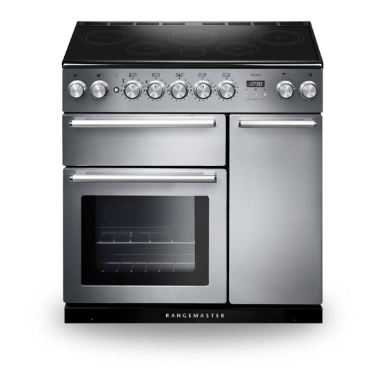
Page 10: Cooker Overview
2. Cooker Overview ArtNo.025-0005 - Overview - 90 induction - 2 button clock & GO grill Fig. 2.1 The 90 induction cooker (Fig. 2.1) has the following features: Fig. 2.2 5 induction cooking zones A control panel Glide-out Grill™ with 4 position Trivet Multifunction oven Tall fan oven The Hob... - Page 11 Make sure that the base of the pan is clean and dry to prevent Fig. 2.4 any residue burning onto the hob panel. This also helps prevent scratches and deposits. Max: 1.85 kW Max: 1.85 kW Max: 1.85 kW Boost: 2.5 kW Boost: 3.0 kW Boost: 2.5 kW Always use pans that are the same size as (or slightly larger...
- Page 12 When the Automatic Heat-up function is activated, the hob Automatic heat-up time at Power level control display will flash alternately between the [A ] setting 100% (min:sec) and the chosen power level. 0:48 Once the Automatic Heat-up time has ended the hob display 2:24 will stop flashing and will show the chosen power level.
- Page 13 Low Temperature Setting, L1/L2 Maximum Operating Time Power Level Each cooking area is equipped with 2 low temperature settings: 2 hours L1 and L2 L1 will maintain a temperature of about 40 °C – ideal for • 6 hours gently melting butter or chocolate. 6 hours L2 will maintain a temperature of about 90 °C –...
-
Page 14: The Glide-Out Grill
The Glide-out Grill Fig. 2.9 Open the door and, using the handle, pull the grill pan carriage forward (Fig. 2.9). The grill has two elements that allow either the whole area of the pan to be heated or just the right-hand half. Adjust the heat to suit by turning the knob. -
Page 15: The Ovens
The Ovens Fig. 2.12 The clock must be set to the time of day before the ovens will work. See the following section on ‘The Clock’ for instructions on setting the time of day. References to ‘left-hand’ and ‘right-hand’ ovens apply as viewed Multi-function oven from the front of the appliance. - Page 16 Conventional Oven (Top and Base Heat) Multifunction Oven Functions Fan Oven This function combines the heat from the top and base elements. It is particularly suitable for roasting This function operates the fan and the heating and baking pastry, cakes and biscuits. element around it.
-
Page 17: Main Oven Light
Operating the Ovens Fig. 2.14 Multifunction Ovens The multifunction oven has two controls: a function selector and a temperature setting knob (Fig. 2.14). Turn the function selector control to a cooking function. Turn the oven temperature knob to the temperature required (Fig. 2.15). -
Page 18: Using The Clock
Using the Clock Fig. 2.17 You can use the clock to turn the left-hand oven on and off. Note: When using the timer functions, first set the clock as required before setting the oven temperature. The oven can be switched on when the cook symbol [ ] is ArtNo.306-0001 - 3-button clock displayed. - Page 19 To Start and Then Stop the Left-hand Oven Fig. 2.23 Set the left-hand oven to automatically start and stop using a combination of the ‘cook period’ and ‘stop time’. You cannot set a start time directly – this is set automatically by a combination of the ‘cook period’...
-
Page 20: Accessories
Accessories Fig. 2.28 Oven Shelves – Left-hand (Main) Oven Shelf guard The oven shelves (Fig. 2.28) are retained when pulled forward but can be easily removed and refitted. Pull the shelf forward until the back of the shelf is stopped by the shelf stop bumps in the oven sides (Fig. -
Page 21: Cooking Tips
3. Cooking Tips Using Your Induction Cooker General Oven Tips If you have not used an induction cooker before please be The wire shelves should always be pushed firmly to the back aware of the following: of the oven. • Make sure that the pans you have or buy are suitable Baking trays with food cooking on them should be placed for use on the induction hob. -
Page 22: Cooking Table
4. Cooking Table DocNo.031-0004 - Cooking table - electric & fan single cavity The oven control settings and cooking times given in the table below are intended to be used Top (T) AS A GUIDE ONLY. Individual tastes may require the temperature to be altered to provide a ArtNo.050-0007 preferred result. -
Page 23: Cleaning Your Cooker
ArtNo.040-0002 - Cleaning - 90 induction GENERIC 5. Cleaning Your Cooker Isolate the electricity supply before carrying out any major Fig. 5.1 cleaning. Allow the cooker to cool. NEVER use paint solvents, washing soda, caustic cleaners, biological powders, bleach, chlorine based bleach cleaners, coarse abrasives or salt. -
Page 24: Grills
Grills Fig. 5.2 The grill pan and trivet should be washed in hot soapy water. After grilling meats or any foods that soil, leave to soak for a few minutes immediately after use. Stubborn particles may be removed from the trivet using a nylon brush. Alternatively, the grill pan can be washed in a dishwasher. -
Page 25: Ovens
Glass Fronted Door Panels Fig. 5.7 The oven door front panels can be taken off so that the glass panels can be cleaned. Move the cooker forward to gain access to the sides (see the ‘Moving the Cooker’ section under ‘Installation’). -
Page 26: Cleaning Table
Cleaning Table Cleaners listed are available from supermarkets or electrical retailers as stated (Table 5.1). For enamelled surfaces use a cleaner that is approved for use on vitreous enamel. Regular cleaning is recommended. For easier cleaning, wipe up any spillages immediately. Hotplate Part Finish... -
Page 27: Troubleshooting
6. Troubleshooting DocNo.053-0006 - Troubleshooting - Induction G5 Interference with and repairs to the hob MUST NOT The induction hob is noisy be carried out by unqualified persons. Do not try When using the induction hob there may be some to repair the hob as this may result in injury and ‘noise’... - Page 28 Power failure In the event of a failure in the electrical supply, remember to reset the clock to make sure that the timed oven continues to operate. Fascia illumination is not coming on (Hi-LITE only) Is the power on? The appliance has developed a fault that cannot be rectified by the user.
- Page 29 The oven light is not working Fig. 6.1 The bulb has probably blown. You can buy a replacement bulb (which is not covered under the guarantee) from most electrical stores. Ask for an Edison ArtNo.324-0005 Oven light bulb screw fitting 15 W 230 V lamp, FOR OVENS. It must be a special bulb, heat resistant to 300 °C (Fig.
-
Page 30: Installation
WARNING! Refer to Before You Start... chapter. Check the appliance is electrically safe and gas sound when you have finished. 7. Installation Dear Installer You will need the following equipment to complete the cooker installation satisfactorily: Before you start your installation, please complete the details Multimeter (for electrical checks). -
Page 31: Positioning The Cooker
WARNING! Refer to Before You Start... chapter. Check the appliance is electrically safe and gas sound when you have finished. Positioning the Cooker Fig. 7.1 ArtNo.090-0028 - 90 cooker min spacing GENERIC Fig. 7.1 and Fig. 7.2 show the minimum recommended 75 mm 75 mm distance from the cooker to nearby surfaces. -
Page 32: Repositioning The Cooker Following Connection
WARNING! Refer to Before You Start... chapter. Check the appliance is electrically safe and gas sound when you have finished. Lowering the Two Rear Rollers Fig. 7.5 To adjust the height of the rear of the cooker, first fit a 13 mm spanner or socket wrench onto the hexagonal adjusting nut (Fig. -
Page 33: Electrical Connection
WARNING! Refer to Before You Start... chapter. Check the appliance is electrically safe and gas sound when you have finished. Electrical Connection Current Operated Earth Leakage Breakers The cooker must be installed by a qualified electrician, in The combined use of your cooker and other domestic accordance with all relevant British Standards/Codes of appliances may cause nuisance tripping, so we recommend Practice (in particular BS 7671), or with the relevant national... -
Page 34: Circuit Diagrams
8. Circuit Diagrams P095199 P095199 P095199 P028728 P095199 P095199 P095199 The connections shown in the circuit diagram are for single-phase. The ratings are for 230 V 50 Hz. Code Description Code Description Code Colour Grill front switch Clock Blue Grill energy regulator Right-hand fan oven thermostat Brown Grill element left-hand side... -
Page 35: Technical Data
COUNTRY OF DESTINATION: GB, IE, FR, NL, DE, SE, BE, AT, CH, LU. Connections Electric 230 / 400 V ~ 50 Hz 3N Dimensions Model NEXUS 90 Induction Overall height minimum 905 mm maximum 930 mm Overall width 900 mm... -
Page 36: Hotplate Efficiency
Hotplate Efficiency Brand Rangemaster Model Identification Nexus Size Type Induction Type of Hob Induction Number of electric zones Zone 1 - Ø cm 18.5 Heating Technology Energy Consumption (ECElectric cooking) - Wh/kg Zone 2 - Ø cm 15.5 Heating Technology Energy Consumption (ECElectric cooking) - Wh/kg Zone 3 - Ø... -
Page 37: Oven Data
Oven Data Brand Rangemaster Model identification Nexus Type of oven Electric Mass Number of cavities Left-hand Efficiency Fuel type Electric Cavity type Multifunction Power - conventional Power - forced air convection Volume Litres Energy consumption (electricity) - conventional kWh / cycle 1.08... - Page 38 Notes...
- Page 39 0800 804 6261 or depending on your mobile network tariff you can For a competitive quote and to arrange for a Rangemaster approved call free on 0370 789 5107. engineer to attend, call Consumer Services on: 0800 804 6261 or...
- Page 40 Registered in England and Wales. Registration No. 354715 Registered Office: Juno Drive, Leamington Spa, Warwickshire, CV31 3RG Rangemaster continuously seeks improvements in specification, design and production of products and thus, alterations take place peri- odically. Whilst every effort is made to produce up-to-date literature, this booklet should not be regarded as an infallible guide to current...