Table of Contents
Advertisement
Quick Links
Advertisement
Table of Contents

Related Manuals for Devolo MicroLlink


Summary of Contents for Devolo MicroLlink
- Page 1 ® MicroLink ISDN i...
- Page 2 The reproduction and distribution of the documentation and software supplied with this product and the use of its contents is subject to written authorization from devolo. We reserve the right to make any alterations that arise as the result of technical development.
- Page 3 Additional information in the Internet at 'www.devolo.com'. Our online services www.devolo.com are available to you around the clock should you have any queries regarding the MicroLink ISDN i. Package Contents...
- Page 4 EU and Switzerland. Connect the device to the public telecommunications network with the sup- plied cable. The declaration of conformity with the basic requirements can be found in the appendix of this manual. devolo MicroLink ISDN i...
-
Page 5: Table Of Contents
4.4 Warranty conditions ..........66 devolo MicroLink ISDN i... -
Page 6: Introduction
Windows operating system. It could also be found in the download area of our homepage www.devolo.com. In case you need more information, please refer to the sys- tem documentation. Highlights of the MicroLink ISDN i... - Page 7 Flash ROM technology—With the help of flash ROM technology, firmware updates can be implemented quickly and easily. Warranty—three years warranty for the MicroLink ISDN i Protected—The MicroLink ISDN i satisfies the CE requirements. devolo MicroLink ISDN i...
-
Page 8: Control Commands
Transfer phase means that a connection to a remote data station (i.e. to another ISDN modem) exists: the ISDN modem is online. This is the case after successful call establishment (outgoing call), as well as after answering devolo MicroLink ISDN i... -
Page 9: Bit-Oriented Registers
To set the bit 6 of register S14, enter the command ATS14.6=1. If you would like this value to be maintained after the ISDN modem is switched off, the new entry can be stored with the command AT*W. devolo MicroLink ISDN i... -
Page 10: Overview Of At Commands And Registers
“Commands and registers“ lists AT commands and registers to change the basic settings of the modem. In addition, you will find AT com- mands and registers in the column “Additional commands and registers“ to affect the performance of the modem. devolo MicroLink ISDN i... -
Page 11: Basic Controlling
Control of DTR effect AT&D AT$D, AT:D, S28 (Bit 7) Control of modem answers ATE, ATQ, ATV, AT\V AT&D, AT-H, AT-M, AT*Q, Control of dial tones AT&G Control of data format S28 (Bit 0-1), S53 devolo MicroLink ISDN i... -
Page 12: Overview Of The At Command Set
Report serial number and hardware release Display product name Report self-test result Report plug&play ID text Display of current ISDN parameters $IBP B-channel protocol setting $IBR Setting the ISDN bit rate $ICI? Display charge information $ICI Delete charge information devolo MicroLink ISDN i... - Page 13 Sets value of last register used to x Display of the current settings Inactivity timer $UPX Firmware upload in flash ROM Messages in short form as a digit Messages in plain text Display of firmware version &V Display configuration profiles devolo MicroLink ISDN i...
- Page 14 Sets bit m in S register n to value x (m = 0 to 7; x = 0 to 1) Query of the value range of a command The complete AT command set can be found in the next chapter 'AT com- mands: Detailed description'. devolo MicroLink ISDN i...
-
Page 15: At Commands: Detailed Description
: DCD is always active *AT&C1 : DCD indicates an existing connection Communications programs normally evaluate the line DCD to verify the pres- ence of a connection. The MicroLink ISDN i supports this evaluation with the setting AT&C1. devolo MicroLink ISDN i... -
Page 16: Establishing A Connection
: Disables DTR dialing AT$D1 : Enables DTR dialing When DTR dialing is enabled and the condition of the control line switches from OFF to ON, the MicroLink ISDN i establishes a connection to the number devolo MicroLink ISDN i... - Page 17 With AT&D2 and AT&D3 as well as DTR = OFF, the MicroLink ISDN i does not return a RING for incoming calls. Automatic call answering is not possi- ble until after the DTR transition from OFF to ON. A RING message with sub- devolo MicroLink ISDN i...
- Page 18 ISDN i is thus reset to its factory defaults. This command is not executed dur- ing existing connections. The dial-number memory, charge statistics, configuration profiles and ISDN settings are not reset by the command AT&F, however. devolo MicroLink ISDN i...
- Page 19 : Report product code in nnn format ATI1 : Report checksum ATI2 : Report checksum result (OK or ERROR) ATI3 : Report version number and firmware release date ATI4 : Display of current parameters ATI5 : Report serial number and hardware release devolo MicroLink ISDN i...
- Page 20 V120 V.120 protocol V110 V.110 protocol HDLC HDLC protocol TRANS Transparent HDLCP HDLC-PPP protocol X.75, T.70NL and Cept/Kit → X75FB1 X.75 HDLCP → → X75FB2 X.75 V.120 HDLCP → X75FB3 X.75 V.120 → V120FB1 V.120 HDLCP devolo MicroLink ISDN i...
- Page 21 $ICI:=0,113,1 (113 = total charges, 1 = last call on port 0). Parameter Value Description Port 0 (V.24 interface) The current-charge display is automatically reset to 0 after the next dialing process. The total-charge information can be deleted with the command AT$ICI=0,0. devolo MicroLink ISDN i...
- Page 22 Standard Description <Value1> 2048 Data block length for X.75 (4-2048) bytes <Value2> 2048 Data block length for HDLCP and HDLC (1-2048) bytes <Value3> Data block length for V.120 (5-259) bytes $IDP Setting the D-channel protocol AT$IDP=<Value1> devolo MicroLink ISDN i...
- Page 23 In addition, the terminal selection digit used for outgoing calls is also estab- lished. All changes are automatically recorded in the nonvolatile memory and are preserved until the next change. Parameter Value Description Port 0 (V.24 interface) devolo MicroLink ISDN i...
- Page 24 All changes are automatically recorded in the nonvolatile memory and are preserved until the next change Parameter Value Description Port 0 (V.24 interface) <"MSN1"> 0..9 Store 1st MSN <"MSN2"> 0..9 Store 2nd MSN <"MSN3"> 0..9 Store 3rd MSN devolo MicroLink ISDN i...
- Page 25 The following settings are valid: Parameter Value Description Port 0 (V.24 interface) <Value1> Telephone service (3.1 kHz telephone service) off Telephone service (3.1 kHz telephone service) on <Value2> Telephone service (analog telephone service) off Telephone service (analog telephone service) on devolo MicroLink ISDN i...
- Page 26 Group 3 fax operation Example To set the MicroLink ISDN i for Group 3 fax operation, enter the following command: AT$ISCO=0,3 The MicroLink ISDN i is set to the value 1 (telephone service (analog tele- phone service)) by default. devolo MicroLink ISDN i...
- Page 27 The command AT\P corresponds to the command AT&Z. The numbers stored with the command AT\P can thus be overwritten with the command AT&Z. The number stored at location 0 is also used for automatic dialing with DTR (see AT$D). devolo MicroLink ISDN i...
-
Page 28: Escape Sequence
The return of the CONNECT message can be suppressed after an invalid escape sequence with this command. Data flow control on the serial port AT\Q0 : No handshake AT\Q1 : Bidirectional XON/XOFF handshake AT\Q2 : Unidirectional CTS handshake devolo MicroLink ISDN i... - Page 29 Set and read the internal register ATSn=x : Sets register n to value x ATSn? : Reads the value of register n ATSn : Sets pointer to register n : Reads the value of last register used devolo MicroLink ISDN i...
-
Page 30: T Inactivity Timer
This command can be used to select numerical short form or plain text for the messages sent by the MicroLink ISDN i to the attached computer. The mes- sages in short form and plain text are covered in the chapter “Description of messages”. devolo MicroLink ISDN i... -
Page 31: Error Correction
AT\V2 provides additional information regarding the correction process in the form of CONNECT xxxxx/REL-LAPB. With the configuration AT\V8 the call establishment messages are issued in the CONNECT xxxxx/ISDN/X75 form. xxxxx stands for the speed with which the connection was established. devolo MicroLink ISDN i... - Page 32 Handling of busy signals/CONNECT messages ATX0 : Busy signal returns NO CARRIER ATX1 : Busy signal returns NO CARRIER ATX2 : Busy signal returns NO CARRIER ATX3 : Busy signal returns BUSY *ATX4 : Busy signal returns BUSY devolo MicroLink ISDN i...
- Page 33 (0 or 1). The marked configuration profile is loaded when switching the adapter on or during an initialization triggered by the transition of DTR from ON to OFF (see command AT&D). Load configuration profile ATZn : Load configuration profile n (n = 0, 1) devolo MicroLink ISDN i...
- Page 34 Register values can be changed using this command. The value set for the bit m can be set to the value x in the corresponding register. If access is not permitted, the value in the S register remains unchanged and the MicroLink ISDN i returns ERROR. devolo MicroLink ISDN i...
-
Page 35: Description Of Registers
Call establishment is not aborted, however, if bit 6 of register S14 has been set to 1 (default = 0). This setting permits the attached computer to send characters to the MicroLink ISDN i during call establish- ment. devolo MicroLink ISDN i... - Page 36 The transition to the command phase is blocked by values >127. Carriage return characters Valid values 0 to 127 decimal Default value 13 (carriage return) Store in nonvolatile memory AT*W The character for M can be redefined in register S3. devolo MicroLink ISDN i...
- Page 37 The contents of register S14 is stored in the nonvolatile memory with the commands AT&W or AT*W. The individual bits have the following signifi- cance: Dec. Description Command Reserved No command echo to host ATE0 Command echo to host ATE1 devolo MicroLink ISDN i...
- Page 38 AT&W or AT*W. The individual bits have the following signifi- cance: Dec. Description Command 0..2 Reserved 3..4 Ignore transition of DTR status AT&D0 → Switch to command phase if DTR AT&D1 → Abort connection if DTR AT&D2 → Reinitialize if DTR AT&D3 5..7 Reserved devolo MicroLink ISDN i...
- Page 39 7N2 (7 data bits, no parity, 2 stop bits) 6..7 Reserved The values in bit 4 and 5 are overwritten with each AT command issued unless the automatic bit rate identification is switched off in register S51. devolo MicroLink ISDN i...
- Page 40 AT&W or AT*W. The individual bits have the following signifi- cance: Dec. Description Command 0..3 No handshake AT\Q0 XON/XOFF bidirectional AT\Q1 RTS/CTS unidirectional AT\Q2 RTS/CTS bidirectional AT\Q3 XON/XOFF unidirectional AT\Q4 XON/XOFF characters are not sent AT\X0 devolo MicroLink ISDN i...
- Page 41 Describtion 0..4 Reserved No parity bit transmission at 7E1 & 7O1 via ISDN Parity bit transmission at 7E1 & 7O1 via ISDN with e. g. X.75 according to the data format from register S23 6..7 Reserved devolo MicroLink ISDN i...
- Page 42 Computer-side bit rate 12,000 bps Computer-side bit rate 14,400 bps Computer-side bit rate 19,200 bps Computer-side bit rate 38,400 bps Computer-side bit rate 57,600 bps Computer-side bit rate 76,800 bps Computer-side bit rate 115,200 bps Computer-side bit rate 230,000 bps devolo MicroLink ISDN i...
- Page 43 AT*W. The individual bits have the following significance: Dec. Description 0..1 Decimal display of S registers Hexadecimal display of S registers Binary display of S registers Message 'Continue with any character...' yes Message 'Continue with any character...' no devolo MicroLink ISDN i...
- Page 44 Error message to network if unit is busy or not oper- ational No response to network if unit is busy or not opera- tional Incoming calls are acknowledged with ALERT No ALERT is sent upon incoming calls No LLC for V.120 LLC for V.120 Reserved devolo MicroLink ISDN i...
- Page 45 Caller ID of the remote station is not dis- played after a CONNECT Caller ID is displayed after a CONNECT Caller ID of the remote station is not dis- played after RING Caller ID is displayed after RING devolo MicroLink ISDN i...
- Page 46 Register S156 contains the number of incorrectly received data packets in the signaling channel (D channel) for every 250 data packets. This register can be read only. The contents of this register can only be reset by switching the adapter off and back on. devolo MicroLink ISDN i...
- Page 47 Status of the S interface Register S159 contains the current status of the ISDN S interface. This reg- ister can be read only. Dec. Description 0..1 Reserved bus not activated bus activated No TEI assigned TEI is assigned devolo MicroLink ISDN i...
- Page 48 Call had incorrect EAZ or incorrect MSN/DN DTR (line S1) was in off-state, call was ignored ISDN adapter had another connection or establishing another con- nection (BUSY) Dial number monitoring not in order Dial number monitoring not in order, no number specified devolo MicroLink ISDN i...
- Page 49 These registers can be read only. The coding is effected as 1TR6 code. S163 S164 Description Bit rate adjustment to 56,000 bps (automatic switching to 56,000 bps at V.120/X.75/HDLC) Other Data transfer 64,000 bps devolo MicroLink ISDN i...
- Page 50 The individual bits in register S180 have the following significance: Dec. Description 0..4 No protocol selected X.75 T.70NL (X.75/T70) V.120 HDLC Transparent HDLC-PPP X.75, T.70NL and Cept/Kit V.110 → X.75 HDLCP → → X.75 V.120 HDLCP devolo MicroLink ISDN i...
- Page 51 The agreed B-channel protocol can be displayed in register S194 after the establishment of a connection. This register can be read only. Dec. Description 0..3 No protocol selected X.75 T.70NL (X.75/T70) V.120 HDLC Transparent HDLC-PPP X.75, T.70NL and Cept/Kit V.110 4..7 Reserved devolo MicroLink ISDN i...
-
Page 52: Description Of Messages
The ISDN supplies the caller ID of the incoming call, if this has not been sup- pressed by the remote station. Register S153 can be used to set whether this number should be displayed together with the RING and/or CONNECT mes- sage. Examples RING;0241938800 CONNECT;0241938800 CONNECT 64000/ISDN/V120;0241938800 devolo MicroLink ISDN i... - Page 53 The following table provides an overview of the CONNECT messages that may be displayed during ISDN operation: Short form Plain text CONNECT 1200 CONNECT 2400 CONNECT 4800 CONNECT 9600 CONNECT 19200 CONNECT 38400 CONNECT 48000 CONNECT 56000 CONNECT 56000/REL CONNECT 64000 CONNECT 64000/REL devolo MicroLink ISDN i...
-
Page 54: V.24 Interface
This signal line is normally always active (ON), but is influenced by the com- mands AT\D and AT&S. Clear to send – CTS = Clear To Send This output is normally always active (ON), but is influenced by the com- mands AT\D, AT\Q and AT&R. devolo MicroLink ISDN i... -
Page 55: Error Messages
S30 or by the AT\Tn command. 001/007 Establishment of connection The DTR signal was deactivated, e.g. by aborted by DTR = off the terminal program. 001/009 Establishment of connection Establishment of connection canceled. aborted by ATH devolo MicroLink ISDN i... - Page 56 Register S30 timer elapsed, inactivity timer ISDN error messages (valid for 1TR6 protocol) 052/000 Abort by network, no reason Dial again. given or reason not translatable 052/128 Normal end of connection The connection was correctly ended by both stations. devolo MicroLink ISDN i...
- Page 57 Dial again later. unit: Unit busy 052/189 Target subscriber: Blocked Check with remote station regarding against incoming connections blockage. 052/190 Target subscriber rejected con- Check with remote station. nection 052/217 Network bottleneck (e.g. con- Dial again later. gestion) devolo MicroLink ISDN i...
- Page 58 053/041 Temporary fault 053/042 ISDN network overloaded 053/044 Channel or service not available 053/047 Service not available 053/049 Service not available 053/050 Requested service not ordered 053/057 Service feature not permitted 053/058 Service feature not available devolo MicroLink ISDN i...
- Page 59 053/069 Requested characteristic does not exist 053/070 Data transfer service available only 053/079 Service or option does not exist 053/088 Remote station does not support requested service 053/091 Invalid transmission network selection 053/127 Unknown ISDN error devolo MicroLink ISDN i...
-
Page 60: Appendix
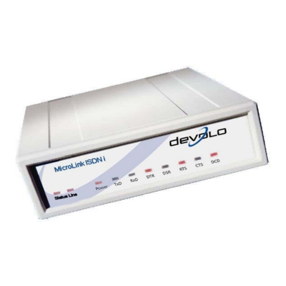
CTS (M2) – ISDN modem clear to send DCD (M5) – Connection established (red and green LED) 4.1.1 Status display Green and yellow LEDs on the front panel of the ISDN terminal adapter serve as the status display of the ISDN connection. devolo MicroLink ISDN i... - Page 61 DTR (S1) Computer operational RTS (S2) Switch on transmit CTS (M2) MicroLink ISDN i clear to send DCD (M5) Connection established LED lights up red for insecure or fax connections LED lights up green for secure connections devolo MicroLink ISDN i...
-
Page 62: Technical Data
PBX with S port Line type DSS1 (Euro ISDN), Basic Rate Interface (point-to- multipoint connection), 1TR6 as well as ISDN PBXs with S ports Power supply 9 – 30V , 9 – 30V Power consumption 3.7 W devolo MicroLink ISDN i... - Page 63 0.7V between the DC source ground and the interface ground occurs (due to the rectifier diode). If these grounds are connected galvanically the electric current flows back via the interface ground—following the lowest resistance. Normally, this does not cause problems. devolo MicroLink ISDN i...
- Page 64 Appendix RJ11 socket contact assignments socket Line Mini-DIN 8 socket pin assignments Explanation Mini DIN 8 (USA) – S1.1 – – S1.2 Mini DIN 8 devolo MicroLink ISDN i...
-
Page 65: Declaration Of Conformity
Interface specification: Termination point of a public telecom. network Spezifikation I-CRT 3: 1994 specification: Diese Erklärung wird verantwortlich abgegeben durch: This declaration is submitted by: Aachen, 21. Januar 2003 Heiko Harbers Aachen, 21 January 2003 Vorstandsvorsitzender devolo MicroLink ISDN i... -
Page 66: Warranty Conditions
Warranty period The warranty period for this devolo product is three years. This period begins at the day of deliv- ery from the devolo dealer. Warranty services carried out by devolo do not result in an extension of the warranty period nor do they initiate a new warranty period. - Page 67 Claims for compensation of lost profits, indirect or consequential detriments, are excluded. devolo is not liable for lost data or retrieval of lost data in cases of slight and ordinary neg- ligence.