Table of Contents
Advertisement
Quick Links
Download this manual
See also:
Service Manual
Advertisement
Table of Contents

Related Manuals for King Canada KC-108C


Summary of Contents for King Canada KC-108C
-
Page 1: Instruction Manual
KING CANADA 8” DRILL PRESS MODEL: KC-108C INSTRUCTION MANUAL COPYRIGHT © 1999 ALL RIGHTS RESERVED BY KING CANADA TOOLS INC. - Page 2 Warranty does not apply to defects due directly or indirectly to misuse, abuse, negligence or accidents, repairs or alterations and lack of maintenance. KING CANADA shall in no event be liable for death, injuries to persons or property or for incidental, special or consequential damages arising from the use of our products.
-
Page 3: General Safety Instructions For Power Tools
GENERAL SAFETY INSTRUCTIONS FOR POWER TOOLS 1. KNOW YOUR TOOL 12. ALWAYS WEAR SAFETY GLASSES. Read and understand the owners manual and labels affixed to Always wear safety glasses (ANSI Z87.1). Everyday the tool. Learn its application and limitations as well as its eyeglasses only have impact resistant lenses, thet are NOT specific potential hazards. -
Page 4: Specifications
SPECIFICATIONS VOLTAGE ..........................................110V HP ............................................1/3HP AMPS ............................................2.5A MOTOR R.P.M........................................1700 Hz ..............................................60 PHASE ............................................1 CHUCK CAPACITY ......................................1/2” DISTANCE BETWEEN SPINDLE AXIS AND COLUMN ........................4-1/2” MAX. SPINDLE TRAVEL ......................................2” MAX. DISTANCE FROM CHUCK TO THE TABLE ............................7” MAX. DISTANCE FROM CHUCK TO THE BASE............................10” RANGE OF SPINDLE SPEEDS (1700 MOTOR R.P.M AT 60Hz) ............620, 1100, 1720, 2340, 3100 R.P.M. -
Page 5: Getting To Know Your Drill Press
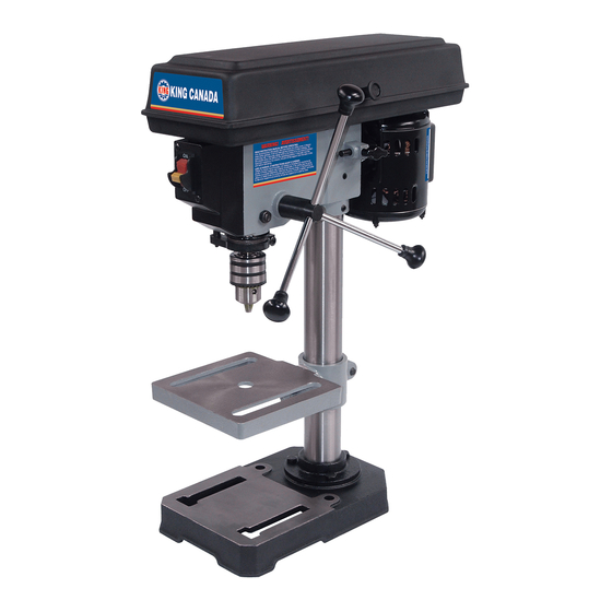
GETTING TO KNOW YOUR DRILL PRESS 8. SPRING CAP 1. BELT GUARD 9. DEPTH POINTER 2. BELT 19. SWITCH TENSION 3. HEAD LOCK SET SCREWS 15. FEED HANDLE 16. CHUCK 4. TABLE SUPPORT 10. DEPTH SCALE FEED SPRING ADJUSTMENT 14. TABLE 18. - Page 6 UNPACKING/TOOLS NEEDED TABLE OF LOOSE PARTS A- Head assembly ..............1 B- Column support assembly ..........1 C- Instruction manual ............1 D- Box of loose parts............1 E- Bag of loose parts ............1 F- Base ..................1 G- Table/support assembly ..........1 TABLE OF LOOSE PARTS IN BAG H- Feed handles ..............3 I- 4mm hex.
-
Page 7: Electrical Connections
The plug must be plugged into an appropriate outlet that is properly installed and grounded in accordance with all local codes and ordinances. 110V WIRING DIAGRAM MODEL:KC-108C WARNING: TO MAINTAIN PROPER GROUNDING OF YOUR DRILL PRESS, DO NOT REMOVE OR ALTER THE GROUNDING PRONG IN ANY MANNER. -
Page 8: Assembly Instructions
ASSEMBLY INSTRUCTIONS Table/Support BASE AND COLUMN ASSEMBLY (FIG.6) assembly 1. Position the base on the floor. Remove the protective covering and discard. 2. Remove protective sleeve from the column and discard. Place the column assembly on the base, align the holes in the column support Column with the holes in the base. - Page 9 ASSEMBLY INSTRUCTIONS INSTALLING THE FEED HANDLES (FIG.10) 1. Locate the three feed handles among the loose parts. 2. Screw the feed handle tightly into the threaded holes in the hub. Feed handle INSTALLING THE BELT GUARD KNOB 1. To attach the belt guard knob, use the knob and a pan head screw from the loose parts bag.
- Page 10 ADJUSTMENTS WARNING! For your own safety, turn the switch OFF and remove the Spring cap plug from the power source before making any adjustements. To avoid injury from thrown parts due to the spring release, follow instructions Notch carefully and wear safety glasses. Boss QUILL RETURN SPRING (FIG.13) 1.
-
Page 11: Operating Instructions
OPERATING INSTRUCTIONS FEEDING Pull down the feed handles with only enough effort to allow the drill to cut. Feeding too slowly might cause the drill to burn...feeding too rapidly might stop the motor...cause the belt or drill to slip... tear the workpiece loose or break the drill bit. -
Page 12: Maintenance & Troubleshooting
It falls off when trying tapered surface. grease and oil. to install it. PARTS DIAGRAM & PARTS LISTS Refer to the Parts section of the King Canada web site for the most updated parts diagram and parts list.