
Related Manuals for KitchenAid KBFA20ER


Summary of Contents for KitchenAid KBFA20ER
-
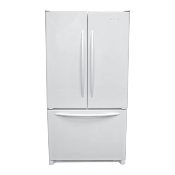
Page 1: French Door
KAR-16 TECHNICAL EDUCATION FRENCH DOOR BOTTOM-MOUNT REFRIGERATOR Models KBFA20ER & KBFA25ER JOB AID 4317387... - Page 2 FORWARD This KitchenAid Job Aid, “French Door Bottom-Mount Refrigerator” (Part No. 4317387), provides the technician with information on the installation, operation, and service of the French Door Bot- tom-Mount Refrigerator. For specific information on the model being serviced, refer to the “Use and Care Guide,”...
-
Page 3: Table Of Contents
Safety First ............1-1 KitchenAid Model & Serial Number Designations ....... 1-2 Model &... - Page 4 — NOTES — - iv -...
-
Page 5: General
GENERAL SAFETY FIRST Your safety and the safety of others is very important. We have provided many important safety messages in this Job Aid and on the appliance. Always read and obey all safety messages. This is the safety alert symbol. This symbol alerts you to hazards that can kill or hurt you and others. -
Page 6: Kitchenaid Model & Serial Number Designations
KITCHENAID MODEL & SERIAL NUMBER DESIGNATIONS MODEL NUMBER MODEL NUMBER PRODUCT GROUP K = KITCHENAID PRODUCT IDENTIFICATION BF = BTM FREEZER, FRENCH DOOR MERCHANDISING SCHEME/SERIES A = ARCHITECT CAPACITY 20 = 20 CU. FT. 25 = 25 CU. FT. MODEL FEATURES... -
Page 7: Model & Serial Number Label & Tech Sheet Locations
MODEL & SERIAL NUMBER LABEL & TECH SHEET LOCATIONS The Model & Serial Number label location is shown below. Model & Serial Number Label The Tech Sheet location is shown below. Bottom Grille Tech Sheet... -
Page 8: Specifications
SPECIFICATIONS Component Specifications all parts 115VAC/60HZ unless noted Compressor run capacitor Volt............. 220 VAC Capacitance ........15 µfd ± 10% 905 BTUH Compressor BTUH ..........Watt ........... 60 Hz / 153 watts Current Lock rotor ......19.0 amps± 15% Current Full load ........ 1.26 amps±... -
Page 9: Kitchenaid Refrigerator Warranty
If you need service, first see the “Troubleshooting” section of the Use and Care Guide. After checking “Trouble- shooting,” additional help can be found by checking the “Assistance or Service” section, or by calling the KitchenAid Customer Interaction Center, 1-800-422-1230 (toll-free), from anywhere in the U.S.A. In Canada, contact your des-... - Page 10 — NOTES —...
-
Page 11: Installation Information
INSTALLATION INFORMATION INSTALLATION INSTRUCTIONS LOCATION REQUIREMENTS • The refrigerator is designed for indoor, household use only. • To ensure proper ventilation for the refrig- erator, allow for a 1/2˝ (1.25 cm) space at Excessive Weight Hazard the top and behind the refrigerator. Use two or more people to move and •... -
Page 12: Electrical Requirements
ELECTRICAL REQUIREMENTS WATER SUPPLY REQUIREMENTS Read all directions before you begin. IMPORTANT: • If you turn the refrigerator on before the water line is connected, turn the ice maker OFF. • All installations must meet local plumbing code requirements. Electrical Shock Hazard •... -
Page 13: Refrigerator Doors
Water Pressure Remove Doors and Hinges A cold water supply with water pressure of between 35 and 100 psi (241- 689 kPa) is re- quired to operate the water dispenser and ice maker. If you have questions about your water pressure, call a licensed, qualified plumber. - Page 14 NOTE: The green, ground wire remains Replace the parts for the bottom hinge as attached to the hinge. shown in Bottom Hinge graphic. Tighten screws. Replace the refrigerator door. Remove the parts for the top hinge, as shown in Top Hinge graphic, and lift the NOTE: Provide additional support for the left-hand side door from the bottom hinge refrigerator door while the hinges are be-...
-
Page 15: Adjusting The Doors
ADJUSTING THE DOORS NOTE: It may take several turns of the roller adjustment screw to adjust the tilt of the re- Depending on the model, the refrigerator may frigerator have two (Style 1) or four (Style 2) adjustable rollers located at the base of the refrigerator. If the refrigerator seems unsteady, or you want the door to close easier, adjust the refrigera- tor’s tilt using the instructions below. - Page 16 — NOTES —...
-
Page 17: Product Operation
PRODUCT OPERATION THEORY OF OPERATION TEMPERATURE MANAGEMENT REFRIGERATOR DAMPER OPERATION The KitchenAid French Door Bottom-Mount Refrigerator uses a thermistor in each cooling When the refrigerator compartment warms compartment to maintain proper tempera- and cooling is required, power is applied to the tures. - Page 18 CABINET AIR FLOW REFRIGERATOR AIR SUPPLY TUNNEL TO FRESH FOOD COMPARTMENT CONTROL DAMPER CRISPER AIR SUPPLY PORT REFRIGERATOR RETURN AIR EVAPORATOR FAN TUNNELS ASSEMBLY EVAPORATOR FREEZER AIR SUPPLY GRILLE EVAPORATOR COVER FREEZER RETURN AIR THROUGH LOUVERS AT BOTTOM OF EVAPORATOR COVER...
- Page 19 WATER DISPENSING FLOW 5/16" O.D. 5/16" OD x 5/16" OD COMPRESSION UNION PLASTIC TUBING ROUTED THRU A FOAMED-IN CONDUIT FILTER THIS AREA WATER WATER DISPENSER RESERVOIR REMOVE WATER TUBING FROM CONDUIT FROM DISPENSER END PLASTIC TUBING 5/16" O.D MAKER WATER SUPPLY CONNECTIO N 1/4"...
-
Page 20: Product Operation
PRODUCT OPERATION Refrigerator Freezer Order Replace Filter Door Holiday Temp OptimIce Reset Mode Alarm Alarm Cool USER INTERFACE USER INTERFACE FEATURES TEMP ALARM The Temperature Alarm combines power out- MAX COOL age and warm alarm features. The max cool feature assists with periods of high refrigerator use, full grocery loads, or POWER OUTAGE temporarily warm room temperatures. -
Page 21: Ice Production Rate
USER PREFERENCES ICE PRODUCTION RATE The user interface allows you to set user pref- • Normal Ice Production: The ice maker erences, if desired. should produce a complete batch of ice every 3 hours. If ice is not being made fast enough, TEMPERATURE DISPLAY (F OR C) adjust the freezer control to a lower (colder) This preference allows you to change the tem-... - Page 22 — NOTES —...
-
Page 23: Component Access
COMPONENT ACCESS This section instructs you on how to service each component inside the French Door Bottom- Mount Refrigerator. The components and their locations are shown below. COMPONENT LOCATIONS User Interface Board & Refrigerator Thermistor Refrig. Door Switch (2) Refrig. Lights (2) Flipper Mullion Water Filter... -
Page 24: Removing The Refrigerator Thermistor, User Interface Board
REMOVING THE REFRIGERATOR THERMISTOR, USER INTERFACE BOARD, DOOR SWITCH, & LIGHT SOCKET User Interface Assembly Electrical Shock Hazard Disconnect power before servicing. User Interface Slots Replace all parts and panels before operating. Failure to do so can result in death or electrical shock. - Page 25 To remove the user interface board: b) Disconnect the wires from the refrigera- tor door switch terminals and remove the a) Disconnect the 3-wire board connec- switch. tor at J1. b) Press and release the locking arm, and disconnect the ribbon cable at Door Switch Wires board connector J2.
-
Page 26: Removing The Motorized Air Door
REMOVING THE MOTORIZED AIR DOOR Remove the two screws from the motor- ized air door housing, and remove the housing from the liner. Air Door Housing Screws Electrical Shock Hazard Disconnect power before servicing. Replace all parts and panels before operating. -
Page 27: Removing The Water Dispenser Switch Assembly
REMOVING THE WATER DISPENSER SWITCH ASSEMBLY Pull the top of the water dispenser out and remove the water dispenser from the liner. Disconnect the two wires from the dis- penser switch terminals. Push and release the locking tabs on the water dispenser switch, and pull the Electrical Shock Hazard switch off the housing pins. -
Page 28: Removing The Water Reservoir
REMOVING THE WATER RESERVOIR Pull the refrigerator away from the wall. Remove the hex-head screw from the dual water valve tube clamp and remove the clamp from the tube. Pull the end of the water tube from the quick-disconnect on the dual water valve. -
Page 29: Removing The Water Filter Connector
REMOVING THE WATER FILTER CONNECTOR Squeeze the sides of the water line fit- ting retainer and slide the retainer off its bracket, then slide the fitting off the re- tainer Fitting Bracket Water Line Fitting Retainer Electrical Shock Hazard Disconnect power before servicing. Replace all parts and panels before operating. - Page 30 11. From inside the refrigerator compartment, 13. Unsnap the left filter connector pin from turn the water filter 1/4-turn counterclock- the housing clip and remove the connec- wise, and remove it from the connector. tor. Clip Water Filter Filter Connector 14.
-
Page 31: Removing The Flipper Mullion
REMOVING THE FLIPPER MULLION Rotate Flipper Mullion Out Electrical Shock Hazard Disconnect power before servicing. Replace all parts and panels before Mullion Screw operating. Failure to do so can result in death or electrical shock. Unplug refrigerator or disconnect power. Open the refrigerator compartment doors. -
Page 32: Removing The Freezer Door Switch & Light Socket
REMOVING THE FREEZER DOOR SWITCH & LIGHT SOCKET b) Disconnect the wires from the freezer door switch terminals and remove the switch. Freezer Door Switch Wires RD & RD-WH Electrical Shock Hazard VI-WH Disconnect power before servicing. Replace all parts and panels before operating. - Page 33 d) Disconnect the two wires from the freezer light socket terminals. e) Press the locking tab to release the light socket, and remove the socket Ground from the reflector. NOTE: If you are re- Wire Clip Freezer Light Wires moving the reflector from the freezer, unclip the green ground wire.
-
Page 34: Removing The Freezer Thermistor
REMOVING THE FREEZER THERMISTOR Place the tip of a flat-bladed screwdriver in the slot of the freezer thermistor cover, then move the screwdriver handle to the left to release the locking tab, and pull out on the left side of the cover to release if from the evaporator cover. -
Page 35: Removing The Ice Maker And Water Fill Tube
REMOVING THE ICE MAKER AND WATER FILL TUBE Fill Tube Electrical Shock Hazard Disconnect power before servicing. Power Replace all parts and panels before Connector operating. 3 Screws Failure to do so can result in death or To remove the water fill tube: electrical shock. -
Page 36: Removing The Evaporator Fan Motor, Defrost Bimetal
REMOVING THE EVAPORATOR FAN MOTOR, DEFROST BIMETAL, DEFROST HEATER, & EVAPORATOR Press the release arm on the left freezer basket glide, and pull the glide out of its support. Electrical Shock Hazard Left Glide Release Arm Disconnect power before servicing. Remove the three hex-head screws from Replace all parts and panels before the left glide support and remove the sup-... -
Page 37: Defrost Heater Evaporator
Remove the four hex-head screws from d) Unclip the fan motor from the housing the evaporator cover and remove the cover and remove the clip, (see the lower from the freezer. left photo), then pull the bottom of the fan motor out, and remove the motor. 11. - Page 38 12. To remove the defrost heater & evapo- f) Pull the bottom of the evaporator rator: out and rotate it up several inches. IMPORTANT: When you rotate the a) Disconnect the left and right main har- evaporator, allow the copper tubing to ness wire connectors from the heater bend, and not the evaporator tubing connectors.
-
Page 39: Removing The Dual Water Valve
REMOVING THE DUAL WATER VALVE Squeeze the sides of the water line fit- ting retainer and slide the retainer off its bracket. Fitting Bracket Water Line Fitting Retainer Electrical Shock Hazard Disconnect power before servicing. Replace all parts and panels before operating. - Page 40 Remove the hex-head screw from the 11. Pull the water valve access cover out tube clamp on the water tube, and re- from the rear of the unit and position it so move the clamp from the tube. you can access the dual water valve. Pull the end of the water tube from the 12.
-
Page 41: Removing The Main Electronic Control Board
REMOVING THE MAIN ELECTRONIC CONTROL BOARD Main Control Board Housing Electrical Shock Hazard Disconnect power before servicing. Replace all parts and panels before Housing operating. Release Arm Failure to do so can result in death or electrical shock. Turn the housing over so you can access the board wire connectors. -
Page 42: Removing The Condenser Fan Motor
REMOVING THE CONDENSER FAN MOTOR Disconnect the power connector from the condenser fan motor. Remove the three hex-head screws from the condenser fan motor and remove the motor. Power Connector Electrical Shock Hazard Disconnect power before servicing. Replace all parts and panels before operating. -
Page 43: Removing The Compressor
REMOVING THE COMPRESSOR Retaining Wire Ground Wire Screw Overload Relay Electrical Shock Hazard Motor Start Capacitor Disconnect power before servicing. Replace all parts and panels before operating. Failure to do so can result in death or electrical shock. Unplug refrigerator or disconnect power. Pull the refrigerator away from the wall so that you can access the rear of the unit. -
Page 44: Removing The Power Supply Cord
REMOVING THE POWER SUPPLY CORD Release the locking arms, and discon- nect the power supply cord connector from the main harness. Remove the hex-head screw from the green ground wire and remove the power supply cord. Power Supply Cord Connector Electrical Shock Hazard Disconnect power before servicing. -
Page 45: Removing The Front And Rear Rollers
REMOVING THE FRONT AND REAR ROLLERS To remove a front roller: a) Tilt the refrigerator back approximately 3˝ and prop the front up. b) Turn the silver (outer) leveling screw to the left (counterclockwise) and re- move the threaded end from the front roller. - Page 46 c) Turn the gold (inner) leveling screw d) Rotate the rear roller so that the brack- to the left (counterclockwise), and re- et tab aligns with the chassis slot, and move the threaded rod from the rear remove the roller. roller you are removing.
-
Page 47: Removing The Condensate Drain Pan & Condenser
REMOVING THE CONDENSATE DRAIN PAN & CONDENSER Remove the rear torx screws from the base pan and the front torx screws from the bottom of the cabinet. Carefully lower the base pan. Be careful not to kink the compressor or condenser tubing. - Page 48 — NOTES — 4-26...
-
Page 49: Component Testing
COMPONENT TESTING Before testing any of the components, perform • Check all connections before replacing the following checks: components, looking for broken or loose wires, failed terminals, or wires not pressed • The most common cause for control failure into connectors far enough. is corrosion on connectors. -
Page 50: Water Dispenser Switch
Electrical Shock Hazard Disconnect power before servicing. Replace all parts and panels before operating. Failure to do so can result in death or electrical shock. WATER DISPENSER SWITCH FLIPPER MULLION Dispenser Switch Mullion Connector Refer to page 4-5 for the procedure for ac- Refer to page 4-9 for the procedure for access- cessing the water dispenser switch. -
Page 51: Defrost Heater
Electrical Shock Hazard Disconnect power before servicing. Replace all parts and panels before operating. Failure to do so can result in death or electrical shock. DEFROST HEATER DUAL WATER VALVE Large Terminals Small Terminals Defrost Heater Connectors Refer to page 4-14 for the procedure for ac- Refer to page 4-17 for the procedure for ac- cessing the defrost heater. -
Page 52: Compressor
Electrical Shock Hazard Disconnect power before servicing. Replace all parts and panels before operating. Failure to do so can result in death or electrical shock. COMPRESSOR Overload Relay & Motor Start Cap Motor Start Capacitor Overload Relay Refer to page 4-21 for the procedure for ac- To test the motor start capacitor, set cessing the compressor. -
Page 53: Diagnostics & Troubleshooting
DIAGNOSTICS & TROUBLESHOOTING DIAGNOSTIC TESTS PROGRAMMING MODE: (FOR PROGRAMMING A NEW CONTROL) NOTE: The Program Code is located on the Serial Plate on this unit after the word Code. Open the Fresh Food door and press and hold the Door Alarm Keypad. Press and hold Freezer Temperature Down Keypad . -
Page 54: Forced Defrost Mode
FORCED DEFROST MODE The forced defrost function is performed using the Freezer display and Refrigerator keypad. En- ter the Forced Defrost Mode by performing the following sequence of events: Open the Fresh Food door and press and hold the Door Alarm Keypad. Press and hold Refrigerator Temperature Down Keypad. - Page 55 SERVICE TEST – 111 FRESH FOOD FAN (IF EQUIPPED) • Press the Refrigerator Up Keypad and Refrigerator Down Keypad to toggle Fresh Food Fan On and Off. NOTE: Display will show state OFF or DC voltage. SERVICE TEST – 112 FREEZER FAN •...
- Page 56 SERVICE TEST – 162 CRUSHER DISPENSER (IF EQUIPPED) • Display shows the state of the Crusher Dispenser (ON or OFF). NOTE: By pushing Actuator pad you can control state of Crusher Dispenser without opening Ice Chute door. SERVICE TEST – 163 WATER DISPENSER (IF EQUIPPED) •...
- Page 57 SERVICE TEST – 182 LED INDICATOR OPERATION • Press the Refrigerator Up Keypad to show operation of LED Indicators. All LED Indicators will flash. Press again and the LED will stop flashing. SERVICE TEST – 191 ICE MAKER WATER VALVE •...
-
Page 58: Troubleshooting
TROUBLESHOOTING Symptom Possible Causes Corrective Action Unit does not run No power to unit Check for power at outlet. Check fuse box/circuit breaker for blown fuse or tripped breaker. Replace or reset. Faulty power cord Check with test light at unit; if no circuit and current is indicated at outlet, replace or repair. - Page 59 Symptom Possible Causes Corrective Action Refrigerator section too cold Refrigerator temperature control set Adjust refrigerator temperature too cold control. Refrigerator airflow not properly Check air flow. adjusted Freezer and refrigerator sections too Temperature controls set too warm Reset temperature controls. warm Poor door seal Level cabinet.
- Page 60 Symptom Possible Causes Corrective Action Frost or ice on evaporator Defrost thermostat faulty Check defrost thermostat. Replace if failed. Evaporator fan faulty Check fan motor. Replace if failed. Defrost heater remains open Check defrost heater continuity. Replace if failed. Defrost control faulty Check control and replace if failed.
-
Page 61: Wiring Diagrams
WIRING DIAGRAMS WIRING DIAGRAM 1... - Page 62 WIRING DIAGRAM 2...
- Page 63 SCHEMATIC DIAGRAM...
- Page 64 — NOTES —...
- Page 65 — NOTES —...
- Page 66 — NOTES —...
-
Page 67: Product Specifications
WARRANTY INFORMATION SOURCES IN THE UNITED STATES: FOR PRODUCT SPECIFICATIONS AND WARANTY INFORMATION CALL: FOR WHIRLPOOL PRODUCTS: 1-800-253-1301 FOR KITCHENAID PRODUCTS: 1-800-422-1230 FOR ROPER PRODUCTS: 1-800-447-6737 FOR TECHNICAL ASSISTANCE WHILE AT THE CUSTOMER’S HOME CALL: THE TECHNICAL ASSISTANCE LINE: 1-800-253-2870...