Mackie D-2 Owner's Manual
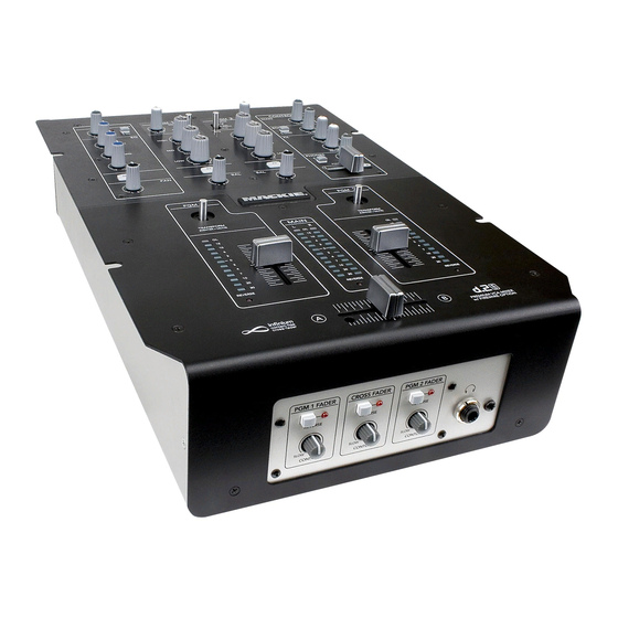
2-channel dj mixer with firewire option
Hide thumbs
Also See for D-2:
- Instalation instructions (4 pages) ,
- Specifications (2 pages) ,
- Manual (4 pages)
Table of Contents
Advertisement
Quick Links
See also:
Manual
2-Channel DJ Mixer with FireWire Option
MIC
OL
SIG
48V
OFF
+3
+50
O O
ON
LEVEL
EQ
U
HIGH
HIGH
-15
+15
U
MID
MID
-15
+15
U
LOW
LOW
-15
+15
ON
PAN
L
R
1
PGM
TRANSFORM
OL
10
7
4
2
0
2
4
7
10
20
30
REVERSE
infinium
contact-free
cross-fader
O W N E R ' S M A N U A L
1
2
PGM
PGM
SOURCE
SOURCE
U
U
LINE/
LINE/
PHONO
PHONO
MAX
O O
MAX
LEVEL
CD
CD
LEVEL
EQ
EQ
HIGH
KILL
+10
KILL
+10
MID
KILL
+10
KILL
+10
LOW
KILL
+10
KILL
+10
FX
FX
BAL
BAL
L
R
L
R
TRANSFORM
MAIN
L
R
OL
10
7
4
2
0
2
4
7
10
20
30
REVERSE
A
B
CONTROL
MAIN
MAX
O O
LEVEL
BOOTH
U
STEREO
O O
MAX
MONO
LEVEL
FX
O O
+15
SEND
O O
+15
RETURN
PHONES
U
PGM
MAIN
O O
MAX
LEVEL
PGM SOURCE
1 1 1
2
2
PGM
OL
10
7
4
2
0
2
4
7
10
20
30
REVERSE
Advertisement
Table of Contents

Related Manuals for Mackie D-2


Summary of Contents for Mackie D-2
- Page 1 2-Channel DJ Mixer with FireWire Option SOURCE LINE/ PHONO LEVEL LEVEL HIGH HIGH KILL KILL KILL TRANSFORM REVERSE infinium contact-free cross-fader O W N E R ’ S M A N U A L CONTROL SOURCE MAIN LINE/ PHONO LEVEL LEVEL BOOTH HIGH...
-
Page 2: Safety Instructions
Important Safety Instructions 1. Read these instructions. 2. Keep these instructions. 3. Heed all warnings. 4. Follow all instructions. 5. Do not use this apparatus near water. 6. Clean only with dry cloth. 7. Do not block any ventilation openings. Install in accordance with the manufacturer’s instructions. -
Page 3: Table Of Contents
Appendix D: Transform Switch Rotation and Fader Replacement...25 Limited Warranty...27 Don’t forget to visit our website at www.mackie.com for more information about this and other Mackie products. Part No. 0014096 Rev. A 7/05 ©2005 LOUD Technologies Inc. All Rights Reserved. Printed in China. -
Page 4: Introduction
The d.2 is the fi rst DJ mixer made by Mackie. We were able to apply our extensive knowledge of mixer design to the d.2, making it a truly professional product with the high-end performance you’ve come to expect from... -
Page 5: Getting Started
Getting Started READ THIS PAGE!! Even if you never reads manuals, please read and digest the safety instructions on page 2, and this page before you begin using the d.2 mixer. Zero the Controls Turn the rear panel POWER switch off. Turn down the LEVEL controls for MIC, PGM 1 and PGM 2, and center all EQ, PAN, and BAL controls. -
Page 6: Hookup Diagrams
DJ Mixer SWA1501 Powered Subwoofer DESIGNED BY MACKOIDS IN WOODINVILLE, WA, USA • MANUFACTURED IN CHINA FABRIQUE EN CHINE • COPYRIGHT ©2005 • "MACKIE", AND THE RUNNING MAN FIGURE ARE TRADEMARKS OF LOUD TECHNOLOGIES, INC. • PATENT PENDING. MAIN OUT BOOTH... - Page 7 Radio Show Recording/Podcasting/having a good old time DESIGNED BY MACKOIDS IN WOODINVILLE, WA, USA • MANUFACTURED IN CHINA FABRIQUE EN CHINE • COPYRIGHT ©2005 • "MACKIE", AND THE RUNNING MAN FIGURE ARE TRADEMARKS OF LOUD TECHNOLOGIES, INC. • PATENT PENDING.
- Page 8 DJ Mixer Powered Subwoofer DESIGNED BY MACKOIDS IN WOODINVILLE, WA, USA • MANUFACTURED IN CHINA FABRIQUE EN CHINE • COPYRIGHT ©2005 • "MACKIE", AND THE RUNNING MAN FIGURE ARE TRADEMARKS OF LOUD TECHNOLOGIES, INC. • PATENT PENDING. MAIN OUT...
- Page 9 CD Turntable (PGM 2) CD Turntable (PGM 1) DESIGNED BY MACKOIDS IN WOODINVILLE, WA, USA • MANUFACTURED IN CHINA FABRIQUE EN CHINE • COPYRIGHT ©2005 • "MACKIE", AND THE RUNNING MAN FIGURE ARE TRADEMARKS OF LOUD TECHNOLOGIES, INC. • PATENT PENDING. BOOTH...
-
Page 10: Rear Panel Features
DJ Mixer DESIGNED BY MACKOIDS IN WOODINVILLE, WA, USA • MANUFACTURED IN CHINA FABRIQUE EN CHINE • COPYRIGHT ©2005 • "MACKIE", AND THE RUNNING MAN FIGURE ARE TRADEMARKS OF LOUD TECHNOLOGIES, INC. • PATENT PENDING. MAIN OUT... -
Page 11: Power Receptacle
3 and 4 for PGM 2. The FireWire card can easily be installed with the help of a small screwdriver. Ask your Mackie dealer about it. (The FireWire card, not the screwdriver.) Each card comes with installation instructions that I have to write before the boss gets back from his vacation in Gary, Indiana. -
Page 12: Top Panel Features
Top Panel Features MIC Input Section 16. MIC LEVEL Control This knob adjusts the gain of the mic preamp for any microphone plugged into the MIC input jack [1]. It ranges from +13 dB to +63 dB of gain. Adjust this knob so that the loudest speaking or shouting that you do into the microphone just barely lights... -
Page 13: Program Input Section
Program Input Section 25. LEVEL Control This knob adjusts the gain of the PGM input signals selected by the position of the SOURCE Select switch [26]. This knob ranges from off to +13 dB of gain at maximum. Adjust this with your good eye on the PRO- GRAM METERS [42], so the level is typically bouncing between the 0 and +4 LEDs. -
Page 14: Control Section
Control Section 32. MAIN LEVEL Control This knob adjusts the main output level at the MAIN OUT XLRs [9] (and to the RCA Main Outs [11] when the LIVE/RECORD switch [12] is out). (Remem- ber, when the LIVE RE- CORD switch is pushed in, the RCA Main Outs are not affected by the MAIN LEVEL control.) -
Page 15: Program Output Section
Program Output Section 40. TRANSFORM Switch The transform switch has three positions: Latch- ing, Center, and Momen- tary. When the switch is Latched, this program’s signal is on, and passes through to the outputs. When the switch is in the center position, this program’s signal is muted at the outputs and FX Sends. - Page 16 45. REVERSE LED This LED lights when the REVERSE switch [48] has been activated for the Crossfader. For more details, see the dis- cussion of the REVERSE switches [48] on the next page. 46. CROSSFADER The crossfader is used to fade between the two PGM signals in the MAIN outputs.
-
Page 17: Front Panel Features
Front Panel Features 47. CONTOUR Controls Use the CONTOUR controls to adjust how fast or slow each fader responds to movement. In the SLOW position, the faders respond in a linear fashion, increas- ing from minimum to maximum at the same rate. In the FAST position, the faders respond logarithmically, increasing from minimum to maximum very quickly, and then changing very little for the remainder of the fader... -
Page 18: Appendix A: Service Information
Appendix A: Service Information Warranty Service Details concerning Warranty Service are spelled out in the Warranty section on page 27. If you think your d.2 has a problem, please do everything you can to confi rm it before calling for service. Doing so might save you from the deprivation of your mixer and the associated suffering. -
Page 19: Repair
Repair Service for Mackie products is available at a factory- authorized service center. Service for Mackie products living outside the United States can be obtained through local dealers or distributors. If your d.2 needs service, follow these instructions: Review the preceding troubleshooting suggestions. -
Page 20: Appendix B: Connections
Appendix B: Connections XLR Connectors The d.2 MIC combo input accepts 3-pin male XLR connectors; the MAIN OUTs accept 3-pin female XLR connectors. These are wired as follows, according to standards specifi ed by the AES (Audio Engineering Society). XLR Balanced Wiring: Pin 1 = Shield Pin 2 = Hot (+) Pin 3 = Cold (–) -
Page 21: Appendix C: Technical Info
Appendix C: Technical Info Specifi cations Frequency Response : Mic Input to any Output: (Trim at 0 dB):+0, –1 dB 20 Hz to 20 kHz Line/CD Input to any Output: ±0.5 dB 20 Hz to 20 kHz Phono input to any Output: ±1 dB of RIAA EQ curve Distortion (THD and IMD): THD @ Main Output, 20 Hz to 20 kHz... - Page 22 Therefore, we reserve the right to change these specifi cations at any time without notice. “Mackie,” and the “Running Man” are registered trademarks of LOUD Technologies Inc. All other brand names mentioned are trademarks or registered trademarks of their respective hold- ers, and are hereby acknowledged.
-
Page 23: Block Diagram
RIGHT LEFT RIGHT MAIN LEFT MAIN PGM1 Voltage Control PGM2 Voltage Control Owner’s Manual... -
Page 24: Gain Structure Diagram
d.2 DJ Mixer... -
Page 25: Appendix D: Transform Switch Rotation And Fader Replacement
Appendix D: Transform Switch Rotation and Fader Replacement Transform Switch Rotation From the factory, the transform switches operate vertically, that is (to get all technical for a moment) fore and aft. You can perform a simple modifi cation to make these switches operate sideways, or even diagonally, to suit your carefully cultivated set of operational preferences. - Page 26 Replacing Faders If the faders ever need to be replaced, this can be done with the help of your trusty screwdriver. 10. Follow steps 1 to 5 and remove the top panel. 11. Take care to only remove the two outer screws of each fader you are replacing, as shown below.
-
Page 27: Limited Warranty
B. Failure to register online or return the product registration card will not void the three-year warranty. C. Service and repairs of Mackie products are to be performed only at a factory-authorized facility (see D below). Unauthorized service, repairs, or modifi cation will void this warranty. - Page 28 16220 Wood-Red Road NE • Woodinville, WA 98072 • USA United States and Canada: 800.898.3211 Europe, Asia, Central and South America: 425.487.4333 Middle East and Africa: 31.20.654.4000 Fax: 425.487.4337 • www.mackie.com E-mail: sales@mackie.com...