Table of Contents
Advertisement
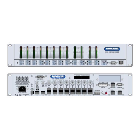
DX8 Digital Audio Mixer/
OL
OL
OL
2
2
2
4
4
4
7
7
7
10
10
10
15
15
15
20
20
20
25
25
25
30
30
30
35
35
35
40
40
40
50
50
50
1
2
3
1
2 3 4 5 6 7 8
DIRECT OUTPUTS
U
THE FOLLOWING ARE TRADEMARKS OR REGISTERED
TRADEMARKS OF MACKIE DESIGNS INC "MACKIE",
"MACKIE INDUSTRIAL", AND THE "RUNNING MAN" FIGURE
CONCEIVED, DESIGNED, AND MANUFACTURED
BY MACKIE DESIGNS INC WOODINVILLE • WA • USA
-20
+20
MADE IN USA • FABRIQUE AU USA • COPYRIGHT ©1999
TRIM
BUS A
MIC
–
POWER
+ G
INPUT
LINE
22-28V DC,
–
G
+
3A MAX
–
–
100
240V
, 50/60Hz, 1A MAX
+
LISTED COMMERCIAL
AUDIO EQUIPMENT
LINE
R
9Z39
Signal Processor
OL
OL
OL
OL
2
2
2
2
4
4
4
4
7
7
7
7
10
10
10
10
15
15
15
15
20
20
20
20
25
25
25
25
30
30
30
30
35
35
35
35
40
40
40
40
50
50
50
50
4
5
6
7
DX8 DIGITAL MIXER
U
U
U
U
U
0
60
0
60
0
60
0
-20
+20
- 30dB +30dB
- 30dB +30dB
- 30dB +30dB
- 30dB +30dB
TRIM
TRIM
TRIM
TRIM
TRIM
BUS B
1
2
3
4
MIC
MIC
MIC
MIC
LINE
LINE
LINE
LINE
LINE
with Automixing
Instruction Manual
15
12
9
6
3
0
3
6
9
12
15
8
LO
EQ
HI
A
MASTER
SERIAL NUMBER
MANUFACTURING DATE
U
U
U
U
60
0
60
0
60
0
60
0
60
- 30dB +30dB
- 30dB +30dB
- 30dB +30dB
- 30dB +30dB
TRIM
TRIM
TRIM
TRIM
5
6
7
8
MIC
MIC
MIC
MIC
LINE
LINE
LINE
LINE
OL
2
4
7
10
DX8 DIGITAL MIXER
15
20
25
30
35
40
50
A
B
LOCK
MODE
B
COMM PORT
12
INPUTS
1 +5V
–
G
+
G
11
OUTPUTS
1
REMOTE BUS
COMM PORT
LOGIC I/O
OUTPUTS
PHANTOM POWER
–
G
+
48V DC
A
B
A
B
ON
1 2 3 4 5 6 7 8
RECORD
POWER
–
G
+
Advertisement
Table of Contents

Related Manuals for Mackie DX8


Summary of Contents for Mackie DX8
- Page 1 TRADEMARKS OF MACKIE DESIGNS INC "MACKIE", "MACKIE INDUSTRIAL", AND THE "RUNNING MAN" FIGURE CONCEIVED, DESIGNED, AND MANUFACTURED BY MACKIE DESIGNS INC WOODINVILLE • WA • USA - 30dB +30dB MADE IN USA • FABRIQUE AU USA • COPYRIGHT ©1999 TRIM...
-
Page 2: Table Of Contents
DX8. 10. Object and Liquid Entry — Do not drop objects into or spill liquids into the inside of the DX8. 11. Damage Requiring Service — The DX8 should be serviced only by qualified service personnel when: A. -
Page 3: Introduction
Priority settings to create sophisticated audio management systems. All settings and text labels are retained in the DX8, and can be saved on the computer’s local drive. The DX8 is UL and CE approved and designed for continuous use in professional fixed installation systems. -
Page 4: Front Panel Features
THE FOLLOWING ARE TRADEMARKS OR REGISTERED TRADEMARKS OF MACKIE DESIGNS INC "MACKIE", "MACKIE INDUSTRIAL", AND THE "RUNNING MAN" FIGURE CONCEIVED, DESIGNED, AND MANUFACTURED BY MACKIE DESIGNS INC WOODINVILLE • WA • USA MADE IN USA • FABRIQUE AU USA • COPYRIGHT ©1999 BUS A POWER... -
Page 5: Rear Panel Features
DX8 settings. A second COMM port on the rear panel duplicates this function, for permanent connection to an installed controller. POWER Use the POWER switch to turn the DX8 on and off. DX8 DIGITAL MIXER LOCK MODE MASTER... -
Page 6: Signal-Flow Diagram
The DX8 can be powered using a 24 VDC power supply. This can serve as the primary power supply for the DX8, or as a backup supply in case of an AC power failure. The DX8 seamlessly switches to the backup supply if there’s a power loss. -
Page 7: Installation
3. INSTALLATION APPLICATION DIAGRAMS DX8 – 7... - Page 8 DX8 – 8...
- Page 9 THE FOLLOWING ARE TRADEMARKS OR REGISTERED TRADEMARKS OF MACKIE DESIGNS INC "MACKIE", "MACKIE INDUSTRIAL", AND THE "RUNNING MAN" FIGURE CONCEIVED, DESIGNED, AND MANUFACTURED BY MACKIE DESIGNS INC WOODINVILLE • WA • USA MADE IN USA • FABRIQUE AU USA • COPYRIGHT ©1999 TRIM TRIM...
- Page 10 DX8 – 10...
- Page 11 The secondary DX8 is used to connect the microphones and instruments for the band. The A and B OUTPUTS are connected to the BUS A and B LINE inputs on the primary DX8, where the signal is mixed with the program sources connected to the primary DX8.
-
Page 12: Connections
DX8 – 12 Connecting Unbalanced Sources It may be necessary to connect a 2-conductor unbalanced input to a balanced input on the DX8. To connect an unbalanced line-level signal: Follow the instructions for connecting a balanced line-level signal above, but wire the connector as... -
Page 13: Ac Power Considerations
It is recommended that you use 18, 20, 22, or 24 gauge wire for the remote control connections, depending on the distance between the DX8 and the remotes. The REMOTE BUS connector is wired as follows: Pin 1 = Ground (Shield) Pin 2 = Data + (with +24 VDC power) Pin 3 = Data –... -
Page 14: Operation
DX8. However, the Quick Start provides a quick overview to get the DX8 set up and working fast. Make sure the power switch is off while setting up and making connections to the DX8. -
Page 15: Using Inputs 1-8
Use this to make broad equalization adjustments to the output signals of the DX8. The output EQ gain can be adjusted from the front panel, and the EQ gain and corner frequency can be adjusted from the PC. -
Page 16: Direct Outputs
REMOTE BUS connection. Each remote control has an 8-position DIP switch that must be set to a unique ID. When the DX8 is first turned on, it polls the REMOTE BUS and identifies the remote controls connected to it by each unique ID. -
Page 17: Front Panel Lock
When the logic input is inactive, the DX8 returns to its base state as long as no other momentary function is in force. Normally, the base state is the state the DX8 was in prior to activating the preset state. -
Page 18: Dx8-Pc Software
It is necessary to install the DX8-PC software on your PC. 1. Make sure no other applications are running. 2. Insert the DX8 CD-ROM into your PC's CD drive, or download the software from install/dx8. 3. The CD should begin the installation automatically. -
Page 19: Overview
Changes made in the PC software are immediately executed in the DX8. Also, changes made by controls on or connected to the DX8 are immediately displayed in the PC software. The graphical user interface is divided into four sections: 1. - Page 20 ← 4. Click PC DX8 to save all the current settings of the DX8 to the PC. The Status box will indicate if the file was successfully saved to the selected location. To open a configuration file: 1. Click Select File in the Configuration File window.
-
Page 21: Indicators And Presets
Windows About This provides information about the DX8-PC software application, including the version and personnel credits. Close Window (ESC) This closes the window that is currently selected (front-most) on-screen. Close All (Ctrl+/) This closes all windows that are currently open on the screen, leaving just the main window open. - Page 22 Presets The DX8 stores up to 16 presets, which can be recalled via the Presets drop-down box. Select a preset in the drop-down box and the settings are instantly recalled from the DX8 memory. Save To Preset Click this button to save the current mixer settings on the DX8 to a preset.
-
Page 23: Buttons
B side) copy the settings of the A Parametric EQ to the B Parametric EQ (and vice versa). Use the Parametric EQ to help eliminate specific troublesome peaks and dips in the room response. DX8 – 23... - Page 24 It is calibrated in milliseconds, with a range from 10 ms to 2500 ms (2.5 seconds). DX8 – 24 • Ratio: This determines the change in output level as a function of the change in input level, once the threshold has been exceeded.
- Page 25 There are three parts to the automixing feature in the DX8. AUTO: This button turns Automixing on or off for an individual channel in the Mix A or Mix B output.
- Page 26 Force-on functions, i.e., at any time the active Force- on functions actually having an effect are those that are applied to inputs with the highest or no priority. DX8 – 26 The following flow chart demonstrates the Force-on/off operation for any particular input:...
- Page 27 This is connected to a Logic Input pin, which forces off the lavalier mic. Output Signal Present: Use this logic signal to light an LED to indicate the presence of a signal at one of the outputs. DX8 – 27...
-
Page 28: Channel Strip
(500Hz-20kHz) of the channel high- frequency shelving EQ. Click and drag up or down to increase or decrease the settings of these controls. DX8 – 28 Mid Peaking EQ These two knobs control the gain (± 15 dB) and the center frequency (20Hz-20kHz) of the channel mid-frequency peaking EQ. -
Page 29: Output Strip
Note that the actual level settings for inputs assigned to Control Groups do not change on the front panel meter or the DX8-PC application main window when a Control Group level is modified. Think of a Control Group as a virtual fader whose gain value is added to the real faders assigned to it. -
Page 30: Specifications
6. SPECIFICATIONS DX8 Block Diagram DX8 – 30... -
Page 31: Dx8 Specifications
Master level @ unity, channel levels @ unity: Single channel to Master Out: (referenced to 1% THD+N) Total Harmonic Distortion (THD+N) (1kHz @ +10 dBu (unity level) 20Hz-20kHz): Mic in to Master Out: < 0.005% –82 dBu –100 dBu DX8 – 31... - Page 32 Mic inputs: Line inputs: Bus A/B inputs: All outputs: Impedances Mic inputs: Line inputs: All other inputs: All outputs: DX8 – 32 PHYSICAL Dimensions (HxWxD): < –90 dB Net Weight: 20Hz–20kHz, ±0.5 dB ELECTRICAL AC Power: –129.5 dBm unweighted DC Power:...
-
Page 33: Service Information
© 2001-2003 All Rights Reserved. Mackie Designs Inc. 6. Service Information In the event that your DX8 should require servicing, please follow these instructions: 1. Call Mackie Tech Support at 1-888-337-7404, 8 am to 5 pm PST (Monday-Friday), to verify the problem and obtain a Return Authorization (RA) Number. -
Page 34: Appendix A: Logic Input Functions
Preset Active Preset 1-16 Priority Inactive None Auto-gate Status Input 1A-8A Input 1B-8B DX8 – 34 Affected I/O None Input 1 to Input 8 Input 1 to Input 8 Input 1 to Input 8 Input 1 to Input 8 Input 1 to Input 8... -
Page 35: Appendix C: Selection Remote Predefined Functions
Mute Group 8 Force On 4 Force On 4 Force On 8 Force On 8 Force Off 4 Force Off 4 Force Off 8 Force Off 8 Preset Recall 4 Preset Recall 4 Preset Recall 8 Preset Recall 8 DX8 – 35... - Page 36 Mackie Designs Inc. 16220 Wood-Red Road NE • Woodinville, WA 98071 • USA US and Canada: 800.898.3211 Europe, Asia, Central and South America: 425.487.4333 Middle East and Africa: 31.20.654.4000 Fax: 425.487.4337 • www.mackie.com E-mail: sales@mackie.com...