Table of Contents
Advertisement
SERVICE MANUAL
Ver. 1.0 2010.06
9-889-883-01
2010F05-1
www.electronicsrepair.net
When a Super Audio CD is played
Playing frequency range
2 Hz to 100 kHz
Frequency response
2 Hz to 40 kHz (–3 dB)
Dynamic range
100 dB or more
Total harmonic distortion rate
0.0035 % or less
Wow and flutter
Value of measurable limit
(±0.001 % W. PEAK) or
less
When a CD is played
Frequency response
2 Hz to 20 kHz (±0.5 dB)
Dynamic range
96 dB or more
Total harmonic distortion rate
0.0039 % or less
Wow and flutter
Value of measurable limit
(±0.001 % W. PEAK) or
less
Output jacks
Jack type Output
level
ANALOG
Phono
2 Vrms
OUT L/R
jacks
(at 50
kilohms)
DIGITAL
Square
–18 dBm
(CD) OUT
optical
OPTICAL*
output
connector
DIGITAL
Coaxial
0.5 Vp-p
(CD) OUT
output
COAXIAL*
connector
* Outputs only the audio signals of the CD
Sony Corporation
Audio&Video Business Group
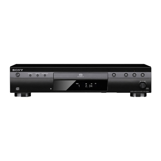
SCD-XE800
Model Name Using Similar Mechanism
Mechanism Type
Optical Pick-up Block Name
SPECIFICATIONS
General
Laser Diode Properties
Power requirements
Power consumption
Power consumption (during standby mode)
Dimensions (w/h/d)
Mass (approx.)
Load
Supplied accessories
impedance
Audio connecting cord
Over 10
Remote commander
kilohms
Batteries
(Light
Design and specifications are subject to change
emitting
without notice.
wave
length: 660
I Standby power consumption 0.5 W.
nm)
I Halogenated flame retardants are not used in
75 ohms
the printed wiring boards.
SUPER AUDIO CD PLAYER
AEP Model
UK Model
SCD-XA5400ES
CDM66F1-DVBU101
KHM-313CAB
Emission duration:
Continuous
Laser Output*: Less than
44.6 µW
* This output is the value
measurement at a
distance of 200 mm from
the objective lens surface
on the Optical Pick-up
Block with 7 mm
aperture.
230 V AC, 50/60 Hz
20 W
0.5 W
430 × 95 × 295 mm incl.
projecting parts
3.5 kg
Red and White plugs (1)
RM-ASU097 (1)
R03 (size-AAA) (2)
Advertisement
Table of Contents

Related Manuals for Sony SCD-XE800


Summary of Contents for Sony SCD-XE800
- Page 1 SCD-XE800 SERVICE MANUAL AEP Model UK Model Ver. 1.0 2010.06 Model Name Using Similar Mechanism SCD-XA5400ES Mechanism Type CDM66F1-DVBU101 Optical Pick-up Block Name KHM-313CAB SPECIFICATIONS General When a Super Audio CD is played Playing frequency range 2 Hz to 100 kHz...
-
Page 2: Table Of Contents
COMPONENTS IDENTIFIED BY MARK 0 OR DOTTED LINE WITH MARK 0 ON THE SCHEMATIC DIAGRAMS AND IN THE PARTS LIST ARE CRITICAL TO SAFE OPERATION. REPLACE THESE COMPONENTS WITH SONY PARTS WHOSE PART NUMBERS APPEAR AS SHOWN IN THIS MANUAL OR IN SUPPLEMENTS PUBLISHED BY SONY. -
Page 3: Servicing Notes
SCD-XE800 SECTION 1 SERVICING NOTES NOTES ON HANDLING THE OPTICAL PICK-UP BLOCK OR BASE UNIT The laser diode in the optical pick-up block may suffer electro- static break-down because of the potential difference generated by the charged electrostatic load, etc. on clothing and the human body. - Page 4 – Bottom view –...
-
Page 5: Disassembly
SCD-XE800 SECTION 2 DISASSEMBLY • This set can be disassembled in the order shown below. 2-1. DISASSEMBLY FLOW 2-2. CASE, FUSE (F001) 2-4. PANEL (LOADING) (Page 5) (Page 6) 2-3. POWER BOARD 2-5. FRONT PANEL BLOCK 2-6. CD MECHANISM DECK BLOCK... -
Page 6: Power Board
SCD-XE800 2-3. POWER BOARD 2-4. PANEL (LOADING) -
Page 7: Front Panel Block
SCD-XE800 2-5. FRONT PANEL BLOCK 2-6. CD MECHANISM DECK BLOCK (CDM66F1-DVBU101) Note 1: ß... -
Page 9: Base Unit
SCD-XE800 2-9. BASE UNIT 2-10. OPTICAL PICK-UP BLOCK (KHM-313CAB) -
Page 10: Test Mode
SCD-XE800 SECTION 3 TEST MODE CDM TEST Note 1: According to the following procedures when you ship it Aging test mode of CDM. (Return it to the customer). Procedure: 1. SERVICE MODE (1) of step 6 and 7 (EEPROM clearness) 1. - Page 11 SCD-XE800 List of trouble log Note: “nnn” of toggle article number is a generation frequency of the error. Test key Toggle article Type Content (Remote commander) number It was not possible to communicate with MTK fi ve seconds more continu-...
- Page 12 SCD-XE800 SERVICE MODE (2) 4. To execute each function, press its number by using numeric button on the remote commander. Note: SERVICE MODE (2) is a service mode of Super Audio CD. 5. To release from this mode, disconnect the power cord.
- Page 13 SCD-XE800 The error code consists of three kinds of error codes. To Clear Laser Hours and Emergency History To Return to the Top Menu of Remocon Diagnosis Perform Step 6. for EEPROM CLEAR of SERVICE MODE (1). Menu M a n u a l A d j u s t A.
- Page 16 SCD-XE800 THIS NOTE IS COMMON FOR PRINTED WIRING BOARDS AND SCHEMATIC DIAGRAMS. • Circuit Boards Location (In addition to this, the necessary note is printed in each block.) For Printed Wiring Boards. For Schematic Diagrams. Note: Note: OUT-SW board • X : Parts extracted from the component side.
- Page 28 SCD-XE800 • Waveforms • IC Block Diagrams – MAIN Board – – MAIN Board – IC504, 506 SI-3010KM-TLS IC1901 TC74LVX4053FT (EL) IC201 DSD1751DBQR IC501 qd (Xout) DSDL DBCK 15 14 DSDR DSCK FILTER PSCK PBCK 3.2 Vp-p MODE 200 ns...
- Page 29 SCD-XE800 – DISPLAY Board – IC802 ML9208-03MBZ03B 64 VDD 63 DA 8 BIT SHIFT 62 CP REGISTER 61 CS 60 RESET COMMAND PORT DECODER DRIVER CONTROL CIRCUIT DRIVER ADRAM 16W ! 2B TIMING TIMING GENERATOR2 GENERATOR1 CGRAM DCRAM 248W ! 35B...
- Page 30 SCD-XE800 • IC Pin Function Description MAIN BOARD IC501 R5F364A6DFA (SYSTEM CONTROLLER) Pin No. Pin Name Description 1, 2 No Use Not used No Use CEC serial data input from the HDMI OUT connector Fixed at “H” in this set...
- Page 31 SCD-XE800 Pin No. Pin Name Description 65 to 73 No Use Not used KEY_INT Wake up signal input terminal LED_LAT Serial data latch pulse signal output terminal Not used No Use Not used No Use I2C Two-way data bus with the clock generator Fixed at “H”...
- Page 32 SCD-XE800 MAIN BOARD IC1101 CXD9927R-B (RF AMP, SERVO DSP) Pin No. Pin Name Description RF offset cancellation capacitor connecting terminal RFGC RF AGC loop capacitor connecting Not used IREF Reference current input terminal AVDD3 Power supply terminal (+3.3V) AGND Ground terminal...
- Page 33 SCD-XE800 Pin No. Pin Name Description XROMCS Chip select signal output to the fl ash ROM Address signal output to the fl ash ROM Read enable signal output to the fl ash ROM 79, 80 HD0, HD1 Two-way data bus terminal with the fl ash ROM...
- Page 34 SCD-XE800 Pin No. Pin Name Description 165, 166 AVDD3 Power supply terminal (+3.3V) EXT_CAP Not used 168, 169 AGND3, AGND18 Ground terminal TXCN TMDS clock signal (negative) output to the HDMI OUT connector Not used TXCP TMDS clock signal (positive) output to the HDMI OUT connector...
- Page 35 SCD-XE800 Pin No. Pin Name Description ADACVDD1, 228, 229 Power supply terminal (+3.3V) ADACVDD2 Rt/DIR_DI Serial data input terminal Fixed at “L” in this set Lt/DIR_DO Serial data output terminal Not used ADACVSS3 Ground terminal ADACVDD3 Power supply terminal (+3.3V) SADCVDD18 Power supply terminal (+1.8V)
-
Page 36: Exploded Views
SCD-XE800 SECTION 5 EXPLODED VIEWS Note: • -XX and -X mean standardized parts, so • The mechanical parts with no reference The components identiÞ ed by mark they may have some difference from the number in the exploded views are not sup-... -
Page 37: Chassis Section
SCD-XE800 5-2. CHASSIS SECTION... -
Page 38: Mechanism Deck Section (Cdm66F1-Dvbu101)
SCD-XE800 5-3. MECHANISM DECK SECTION (CDM66F1-DVBU101) -
Page 39: Base Unit Section
SCD-XE800 5-4. BASE UNIT SECTION... -
Page 40: Electrical Parts List
SCD-XE800 SECTION 6 DISPLAY MAIN ELECTRICAL PARTS LIST Note: • Due to standardization, replacements in • CAPACITORS When indicating parts by reference num- the parts list may be different from the uF: µF ber, please include the board name. parts specifi ed in the diagrams or the com- •... - Page 41 SCD-XE800 MAIN Ref. No. Part No. Description Remark Ref. No. Part No. Description Remark C202 1-164-217-11 CERAMIC CHIP 150PF C1110 1-165-908-11 CERAMIC CHIP 1uF C203 1-115-416-11 CERAMIC CHIP 0.001uF C1111 1-104-658-91 ELECT 100uF C204 1-114-263-91 ELECT 47uF C1112 1-126-947-11 ELECT...
- Page 42 SCD-XE800 MAIN Ref. No. Part No. Description Remark Ref. No. Part No. Description Remark C1186 1-127-715-11 CERAMIC CHIP 0.22uF C2130 1-162-970-11 CERAMIC CHIP 0.01uF C1187 1-104-658-91 ELECT 100uF C2502 1-164-172-11 CERAMIC CHIP 0.0056uF C1190 1-104-658-91 ELECT 100uF C2503 1-127-760-11 CERAMIC CHIP 4.7uF 6.3V...
- Page 43 SCD-XE800 MAIN Ref. No. Part No. Description Remark Ref. No. Part No. Description Remark IC1102 6-715-450-01 IC MX29LV320DBTI-70-SCD-0803 R286 1-216-809-11 METAL CHIP 1/10W R287 1-216-809-11 METAL CHIP 1/10W IC1103 6-714-152-01 IC R1EX24064ASAS0A IC1104 6-714-642-01 IC EM638165 TSA-6G R288 1-216-809-11 METAL CHIP...
- Page 44 SCD-XE800 MAIN Ref. No. Part No. Description Remark Ref. No. Part No. Description Remark R566 1-216-809-11 METAL CHIP 1/10W R1154 1-216-864-11 SHORT CHIP R567 1-216-809-11 METAL CHIP 1/10W R1155 1-216-864-11 SHORT CHIP R568 1-216-809-11 METAL CHIP 1/10W R1156 1-216-809-11 METAL CHIP...
- Page 45 SCD-XE800 MAIN MOTOR OUT-SW POWER Ref. No. Part No. Description Remark Ref. No. Part No. Description Remark R1783 1-216-833-11 METAL CHIP 1/10W < SWITCH > R1801 1-211-990-11 METAL CHIP 0.5% 1/10W SW010 1-572-086-11 SWITCH, LEAF (CHUCKING) R1900 1-216-857-11 METAL CHIP...
- Page 46 SCD-XE800 POWER TRANS Ref. No. Part No. Description Remark Ref. No. Part No. Description Remark 0 D107 8-719-053-18 DIODE 1SR154-400TE-25 0 D108 < THERMISTOR > 8-719-053-18 DIODE 1SR154-400TE-25 0 D109 8-719-053-18 DIODE 1SR154-400TE-25 0 TH50 0 D110 1-804-046-21 THERMISTOR, POSITIVE (RXE030)