
Related Manuals for TurboChef Encore Touch Rapid


Summary of Contents for TurboChef Encore Touch Rapid
- Page 1 Service Manual fo r t h e t u rb o c h e f e n c o re tou ch ra pid cook o ve n CAUTION: Read the instructions before using the machine. ©2015 TurboChef Technologies, Inc.
- Page 2 For further information, call 800.90 TURBO +1 214.379.6000 The information contained in this manual is important for the proper installation, use, maintenance, and repair of this oven. Follow these procedures and instructions to help ensure satisfactory cooking results and years of trouble-free service. Errors –...
-
Page 3: Table Of Contents
Table of Contents Important Safety Instructions General Safety Information Reducing Fire Risk Grounding Instructions Power Cord Replacement or Removal Precautions to be Observed Before and During Servicing to Avoid Possible Exposure to Excessive Microwave Energy RF Interference Considerations Protective Earth (Ground) Symbol Equipotential Bonding Symbol Specifications and Installation Theory of Operation... - Page 4 Info Mode Information Screen Serial Number Menu Version Sage Firmware Version Phoenix Firmware Version Service Number Voltage - View Incoming Tutorials Counters Screen Cook Counter Total Cook Time Magnetron Time Total Time (oven on) Fault Log Power Cycles Options Screen Editing yes/no Cook More yes/no Load Menu yes/no...
- Page 5 Test Mode Magnetron Test Top Heater Test Bottom Heater Test Control Blower Speed Manufacturing (Mfg) Screen Oven Model Serial Number Load Menu from USB or Smart Card Save Menu to USB or Smart Card Firmware Update Edit Mode Edit Set Temperature Edit Bottom Temperature Offset Access Edit Items Screen Name a Group...
- Page 6 Oven Door Removing/Reinstalling the Oven Door Adjusting the Oven Door Interlock Switches Relay - K3 Monitor Adjusting the Primary, Secondary, and Monitor Switches Measuring RF Leakage for Microwave Safety Troubleshooting Microwave System Capacitors Testing a Capacitor Filament Transformers Wiring the Filament Transformers High-Voltage Transformers Wiring the High-Voltage Transformers Testing a Filament or High-Voltage Transformer...
- Page 7 Power Components Electrical Compartment Cooling Fan Electrical Compartment Thermostat Electrical Compartment Thermocouple EMI Filter Fuses Power Supply Relay - K6 Voltage Relay - K7 All Cooling Fans Voltage Sensor Wire Harnesses Troubleshooting Filtering System Catalytic Converter Air Filter Vent Catalyst Troubleshooting Troubleshooting Overview of Troubleshooting...
- Page 8 Oven Schematic and Wire Harnesses Relay Schematic Oven Schematic Wire Harness: Heater Wire Harness: Cooling Fans Wire Harness: HV Microwave Circuit 1 Wire Harness: HV Microwave Circuit 2 Wire Harness: Low Voltage Wire Harness: Main Line Voltage 67-68 Encore 2 Appendix - Replacing Oven Components Replacing Oven Components Oven Exterior Impingement System...
-
Page 9: Important Safety Instructions
IMPORTAnT SAfETy InSTRuCTIOnS WARNING: When operating this oven, strictly adhere to the following safety precautions to reduce the risk of burns, electric shock, fire, injury, damage to oven or property near oven, or possible exposure to excessive microwave energy. GEnERAL SAfETy InfORMATIOn Read all instructions before using this appliance. -
Page 10: Grounding Instructions
SAfETy InSTRuCTIOnS GROunDInG InSTRuCTIOnS This appliance must be grounded. In the event of an electrical short circuit, grounding reduces the risk of electric shock by providing an escape wire for the electric current. This oven is equipped with a cord that has a grounding wire with a grounding plug, which must be plugged into an outlet that is properly installed and grounded. -
Page 11: Rf Interference Considerations
Rf InTERfEREnCE COnSIDERATIOnS This oven generates radio frequency signals. This device has been tested and was determined to be in compli- ance with applicable portions of FCC part 18 requirements and to the protection requirements of Council Directive 89/336/EEC on the approximation of the laws of the Member States relating to electromagnetic compatibility at the time of manufacture. - Page 12 SAfETy InSTRuCTIOnS This page intentionally left blank.
-
Page 13: Specifications And Installation
Specifications and Installation... -
Page 15: Theory Of Operation
1: Oven Dimensions Theory of Operation Dimensions Oven Dimensions The TurboChef Encore Touch oven uses radiant heat in combination with high-speed air impingement and side- Height - Single Oven launched microwave to cook food rapidly without com- with legs: 23” (584 mm) promising quality. -
Page 16: Certifications
United States. WARNING: The oven must be properly placed on a food station at all times. TurboChef will not recognize a fallen oven as Single Phase (6200 watts) a warrantable claim and is not liable for any US/Canada: 208/240 VAC*, 60 Hz, 30 A injuries that may result. -
Page 17: Installing The Oven
Installation near Open Heat Source align with the leg holes of the oven. For details, contact customer support at When placing a TurboChef oven near an open heat source (see Figure 2, below), strictly adhere to the fol- 800-90TURBO or +1 214-379-6000. -
Page 18: Oven Restraint Kit
800.90TURBO or +1 214.379.6000. figure 3: Voltage Selection ChefComm Limited Ventilation Part Number: CON-7016 The TurboChef Encore oven has been approved ChefComm Limited is a “read-and-upload only” by Underwriter’s Laboratory for ventless operation version of ChefComm Pro that helps ensure menu... - Page 19 Daily and Quarterly Maintenance...
-
Page 21: Daily Maintenance
TurboChef® Oven Cleaner (Product Number: 103180), only TurboChef®-approved cleaning chemicals. Failure to TurboChef ® Oven Guard (Product Number: 103181), Kay adhere to these procedures or the use of any other cleaning ClickSan® sanitizer, nylon scrub pad, clean damp and dry... - Page 22 Step 8: Clean the Oven Cavity Step 7 DO NOT spray TurboChef ® Oven Cleaner into the holes in the oven cavity. • Apply Oven Cleaner to a towel or nylon scrub pad and clean the top, sides, and bottom of the cavity. DO NOT apply excessive pressure to the waveguide covers (A), located on each side of the cavity.
-
Page 23: Quarterly Maintenance
Quarterly Maintenance Supplies and Equipment To ensure optimal oven performance, complete the Required: Phillips screwdriver, clean towels, rubber gloves following cleaning steps once per quarter or more for handling catalytic converter. frequently as required. Recommended: dust mask, vacuum, bristle or paint brush 1. - Page 24 CLEAnInG This page intentionally left blank.
-
Page 25: Oven Controls And Cooking
Oven Controls and Cooking... -
Page 27: Oven Controls
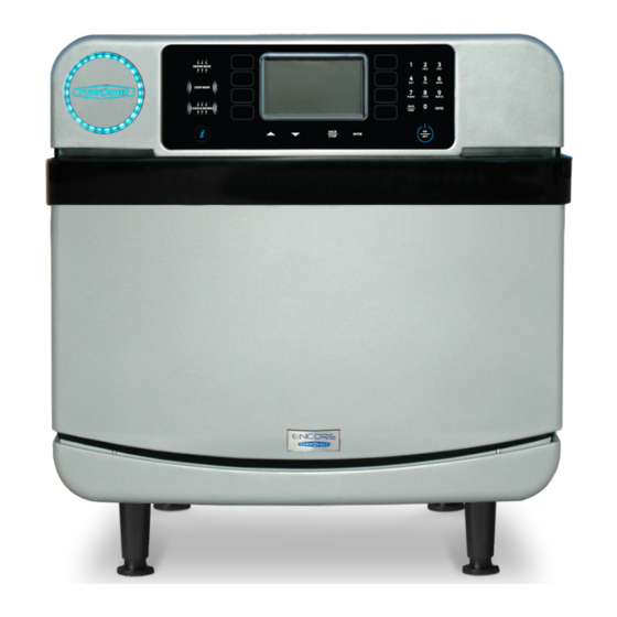
figure 4: Oven Controls, Oven Off figure 5: Oven Controls, Item Select Note: Display options vary depending on which features are enabled. Oven Controls 6. Groups/Items (1-8 and 9-16) The oven contains 16 food groups divided 1. Menu Icon/Temperature Icon into 2 groups of 8. -
Page 28: Menu Cook Mode
OVEn COnTROLS AnD COOKInG Menu Cook Mode The oven is preprogrammed with recipe settings at the time of manufacture and is ready to operate out of the box. New menu settings can be loaded via USB or smart card (page 21-22) or programmed manually (page 23). settings are not present, the oven will cook only in manual mode (page 13). - Page 29 Step 4: Place food in the Oven WARNING: Inside of oven and oven door are hot! Step 5: Select a Group NOTE: Touch “More Groups” to view additional groups. Step 6: Select an Item NOTE: Touch “More Items” to view additional items. Step 7: Cooking NOTE: To immediately terminate a cook cycle, touch “STOP.”...
- Page 30 OVEn COnTROLS AnD COOKInG Step 9: Cook More / Brown More / Cook & Brown More NOTE: This option must be enabled in order to cook an item beyond its original cook time (see page 15 for details). To cook an item longer than its original cook time, touch one of the icons on the screen: - Touch “Cook More”...
-
Page 31: Manual Cook Mode
Manual Cook Mode Manual Cook Mode allows cooking “on the fly,” whereas Menu Cook Mode (page 10) allows cooking from preset cook settings. To access Manual Mode, touch the Manual icon when the oven is off or cool- ing down (page 9) or touch the Menu/Manual toggle on the Menu Mode screen (page 10). NOTE: If the “Manual”... - Page 32 OVEn COnTROLS AnD COOKInG ...continued from previous page. d. Select an item to overwrite. 8. Save to Menu NOTE: To cancel, touch “CANCEL.” If you want to save a manual mode setting into the oven menu (page 10), touch “Save to Menu.”...
- Page 33 Info Mode...
-
Page 35: Info Mode
Info Mode Info Mode: Options Screen To access Info Mode, touch the “i” icon when the From the Info Mode Information or Counters oven is off, cooling down, or in manual mode. screen, touch “Login” to access the Options screen. From the Info Mode screen, access: When prompted, input the password 9 4 2 8... - Page 36 InfO MODE Light Ring yES/nO: Cooking Stone yES/nO: The light ring provides visual cues in regards to oven The “Stone” option should be set to: operation and how much cook time is remaining. - “YES” if a baking stone is being used - “NO” if only a wire rack is being used VAC yES/nO: When VAC is set to YES the incoming voltage will be “YES” increases the temperature of the bottom half...
- Page 37 Language: Sound Volume: The default language is English. To change to Touch “Volume” and use the plus or minus icons or another language, touch “Language: English” slider to increase or decrease the oven sound. and then touch the preferred language and touch Set Date: “ENTER.”...
-
Page 38: Test Mode
InfO MODE Info Mode: Service Screen Auto On - yES/nO: “Auto On” is a feature that turns the oven on auto- matically at a specific time of day. figure 14: Info Mode, Service Screen from the Service screen, view: figure 12: Info Mode, Auto On - Fault Log 1. -
Page 39: Magnetron Test
Counters and Timers: Magnetron Test: To turn on the magnetrons, touch and hold the “Magnetron Test” icon. To turn them off, release the icon. While holding the “Magnetron Test” icon, measure the current transformer wire on the control board for 13-15A (240 V) or 15-17A (208 V). Current Transformer figure 17: Info Mode, Counters... -
Page 40: Oven Model
InfO MODE Oven Model: Control Blower Speed: Touch the “Blower” icon to increase the blower The oven model shown on the screen must match motor speed in 10% increments. the model of the oven being serviced. If this set- ting must be changed, select the proper oven model from the list shown on the display. -
Page 41: Load Menu From Usb Or Smart Card
Load Menu from uSB or Smart Card NOTE: When loading a menu from a USB, a copy of the current oven menu will be saved NOTE: To update a menu, you may need to verify to the USB. that access to the Load Menu screen is turned on. See page 15 for details. -
Page 42: Firmware Update
Once installation is complete, the oven will display “Installation Complete.” TurboChef may at some point recommend a firmware update. The update will make sure your oven is operat- ing at its maximum efficiency, but should not affect cooking results or menu settings. -
Page 43: Edit Mode
Edit Mode... -
Page 45: Edit Set Temperature
If recipe settings are not cooking as desired, consult To change the temperature offset, your menu developer, authorized distributor, or TurboChef Customer Support. 1. Place the oven in Edit Mode. To change a set temperature, 1. Place the oven in Edit Mode. -
Page 46: Access Edit Items Screen
EDIT MODE 2. Touch the current offset temperature. 2. Select a Group. NOTE: The set temperature will apply only to the groups adjacent to it. After changing a temperature, be sure to check the temperature for both groups 1-8 and goups 9-16. -
Page 47: Delete A Group
Delete a Group 2. Touch the Group to be moved. To delete a group, 1. Place the oven in Edit Mode. 3. Touch “Move Group.” 2. Touch the group to be deleted. 4. The group that is to be moved will be highlighted blue. -
Page 48: Item Editing Options
EDIT MODE Item Editing Options 4. Touch an item to be edited. From the Item Editing Options screen, the operator can: To access the Edit Settings screen, - Edit Settings - Name an Item 1. Touch “EDIT” to place the oven in Edit Mode. - Change the Group - Move an Item - Delete an Item... -
Page 49: Edit Settings
Edit Settings From the Item Editing Options screen (page 26), select “Edit Settings.” From the Edit Settings screen the operator can: - Edit % Time - Edit % Air - Edit % Microwave - Edit Cook Time - Name an Item - Run a Test Cook Cycle Edit % Time Touch a % Time icon to change, enter the new percentage, and touch “ENTER.”... - Page 50 EDIT MODE Edit Cook Time Touch the current cook time. The maximum allowable cook time is 10:00. Using the number keypad, enter the cook time and touch “ENTER.” Once all changes are made, touch “SAVE.” name an Item Touch the current name. Using the keypad, input the name and touch “ENTER.” Once all changes are made, touch “SAVE.”...
-
Page 51: Name Item
Caps lock Add from Cookbook The cookbook is a listing of all TurboChef recipes available for general market use, as found at cookbook.turbochef.com. From the “Editing Options” screen (page 26), touch “Add from Cookbook.” Cook settings can be filtered by “Course Type”... -
Page 52: Change Group
EDIT MODE Change Group From the “Editing Options” screen (page 26), select “Change Group.” Select a new group. Touch an item space to indicate where the item will be moved. NOTE: If an item is moved to a space that already contains settings, the old settings will be overwritten. -
Page 53: Delete Item
Delete Item From the “Editing Options” screen (page 26), select “Delete Item.” Touch “OK” to delete the item. NOTE: Once an item is deleted, it cannot be recovered. - Page 54 EDIT MODE This page intentionally left blank.
-
Page 55: Oven Systems
Oven Systems... -
Page 57: Impingement System
Impingement System High Limit Thermostat The high limit thermostat is a 250 VAC, 3-pole, The impingement system rapidly heats, filters, and manual-reset thermostat with a trip point of 572 º F recirculates air into the cook cavity. (300 º C). The thermostat interrupts power to the bottom or top heater in the event of an abnormal This section contains information about the condition. -
Page 58: Oven Door
OVEn SySTEMS Oven Door 4. Carefully remove the oven door by pulling it away from the oven. This section contains information about the 5. Reinstall (or replace) the door by securing it via following components: the hex screws, verifying that the door is parallel - Oven door to the oven frame. -
Page 59: Interlock Switches
The door must completely snap shut on its own. If the 1. Ensure the oven has been at operating temperature door sticks or force is needed to finish closing it, it is for at least fifteen minutes. out of adjustment. 2. -
Page 60: Measuring Rf Leakage For Microwave Safety
OVEn SySTEMS Measuring Rf Leakage for Microwave Safety 5. Close the oven door and press the Cook key. The microwave system will turn on. WARNING: This procedure requires work with 6. Measure microwave emission around the door as hot surfaces and water loads. To avoid burns, be shown in the adjacent illustration, moving the careful when testing. -
Page 61: Microwave System
Microwave System 1. Disconnect the oven from the power source. 2. Fully discharge the capacitor. The oven employs left and right microwave 3. Isolate the capacitor from the circuit. systems. In the case of an over-current situation, 4. Check for an open or shorted capacitor by the F3 fuse (20 amp) will blow, shutting off both placing ohmmeter leads between the capacitor systems immediately. -
Page 62: High-Voltage Transformers
OVEn SySTEMS High-Voltage Transformers Testing a filament or High-Voltage Transformer The high-voltage transformers are ferro-resonant, DANGER: Never attempt to measure the which limits faulty currents and minimizes magnetron secondary voltage values of the HV power changes due to input voltage changes. The high- transformers. -
Page 63: Testing A High-Voltage Diode
High Voltage Transformers Primary Voltage, frequency, Taps, Secondary Taps and Resistance and Resistance 4, Ground, 53.60–65.52 Ω NGC-3062-1 208 VAC, 60 Hz, 1 & 2, 0.819–1.001 Ω 240 VAC, 60 Hz, 1 & 3, 0.972–1.188 Ω 3, Ground, 57.52–70.30 Ω NGC-3062-2 230 VAC, 50 Hz, 1 &... -
Page 64: Magnetron Thermostats
OVEn SySTEMS Magnetron Thermostats The magnetron thermostats are “open-on rise.” They are designed to open at 270 º F (132 º C), which triggers an F5 fault. filament and High NOTE: The magnetron thermostats are wired in Voltage Terminals series. If one opens, the control will switch off both magnetrons until the open thermostat closes. -
Page 65: Control System
Control System LED Light Ring This section contains information about the The LED light ring provides visual cues in regards following components: to oven operation and counts down the final 30 sec- - Control board onds of each cook cycle. - Display and UI Control Board (Phoenix) - Ethernet extension cable Micro SD... -
Page 66: Power Components
OVEn SySTEMS Power Components fuses The F1 and F2 fuses are 12-amp, ATMR, class CC. This section contains information about the The F3 fuse is 20-amp, ATMR, class CC. The F1 following components: fuse (via blue wire) and F2 fuse (via brown wire) - Electrical compartment cooling fan are designed to blow if an over-current situation is - Electrical compartment thermostat... -
Page 67: Voltage Sensor
Let the The wire harnesses distribute power to the oven’s catalytic converter air dry before reinstalling. electrical components. For oven schematic and If TurboChef Oven Cleaner is not available, wire harness drawings, see pages 63-68. use only distilled water. Troubleshooting... - Page 68 OVEn SySTEMS This page intentionally left blank.
-
Page 69: Troubleshooting
Troubleshooting... -
Page 71: Overview Of Troubleshooting
Overview of Troubleshooting f3: Magnetron Current Low This fault is displayed when the current transformer This section contains information on the (CT) on the I/O control board detects less than 10 following: amps. The fault is monitored when the microwave is - Fault code descriptions on during a cook cycle or in Test Mode. -
Page 72: F7 Rtd Open
TROuBLESHOOTInG f7: RTD Open RTD senses +650°F (343°C) for more than 40 This fault is displayed when the control detects that seconds but less than 2 minutes. The fault will only one or both of the RTDs is “open.” The display will appear in the fault log and will not terminate a cook show “999 º... -
Page 73: Fault Code Troubleshooting
fault Code Troubleshooting From Test Mode, you can run oven diagnostics and check fault counts. To access Test Mode see page 19, or turn on Diagnostic mode (see “Diagnostic Mode Yes/No” on page 16) To locate oven components for testing, adjustment, or replacement, see the Appendix. Troubleshooting: f1: BLOWER (Blower Running Status Bad) Is the blower Is the oven type Cycle power to the oven. - Page 74 TROuBLESHOOTInG Troubleshooting: f2: LOW TEMP (Cook Temperature Low) Is the H1 or H2 heater defective? Is the high-limit Reset and determine why it tripped – excess grease thermostat tripped? 1. Isolate the heater circuits by buildup, etc. The reset disconnecting them from the button is on the back panel high-limit switch.
- Page 75 Troubleshooting: f3: MAG CuRR (Magnetron Current Low) Is the K6 mechanical Energize the mag- relay in good working Intl. U.S. netron circuit from Is the oven International or U.S.? order? Test Mode (page 19). Are there 10+ amps present on the cur- Confirm the F3 fuse is a Replace the F3 fuse and Replace...
- Page 76 TROuBLESHOOTInG Troubleshooting: f4: MOnITOR (Door Monitor Defective) Is the connector to the monitor Seat the connector switch properly seated? on the switch. Are the switches opening in the correct sequence (P, S, M) while the oven is hot? (Ensure Is the 20-amp F3 fuse blown? Replace the F3 fuse.
- Page 77 Troubleshooting: f6: EC TEMP (Electrical Compartment Temperature High) Is the oven in an area of moderate temperature (120ºF [49ºC] or cooler)? Does the oven have Relocate oven to room to ventilate? cooler area. Move oven to open area or remove Required clearances: items that are in close proximity.
- Page 78 TROuBLESHOOTInG Troubleshooting: f8: HEAT LOW Set oven type to Encore Is the oven type set to Is the blower motor “Encore”? (see page 20) and try warming up the moving air? Check in oven again. Does the Test Mode - see page fault persist? 20, section “Control Blower Speed.”...
- Page 79 Update the firmware the oven have the latest firmware version? Insert a USB thumb (page 22). (Check with TurboChef customer support). drive. Does the oven detect the USB drive? Replace the USB/smart Card Reader and USB Verify the rear air filter extension cable.
-
Page 80: Cook Door Open" Message When Door Is Closed
TROuBLESHOOTInG non-fault Code Troubleshooting This section provides troubleshooting tips for issues that may occur independently of an oven fault. Troubleshooting: “Cook Door Open” Message when Door is Closed Refer to the F4: MONITOR Enter Test Mode (page 19) Is “F4 MONITOR” troubleshooting procedures on and observe the status indi- fault present? -
Page 81: No Display (Screen Is Blank)
Troubleshooting: no Display – Screen is Blank Unplug the oven for 20 Return the oven to service. seconds and plug it back in. Did the display come back? Is the display white or does it Are any of the LEDs on have stripes across it? the back of the display lit? Replace the power... -
Page 82: Touch Screen Is Locked Up Or Unresponsive
TROuBLESHOOTInG Troubleshooting: Touch Screen is Locked up or unresponsive Follow the “Troubleshooting: Is the problem related to Is the screen blank? No Display-Screen is Blank” specific food items? steps on Page 55. Reload the menu (page 21). Doees the oven show a door open message? Follow the “Troubleshooting: ‘Cook Door Open’... -
Page 83: Oven Keeps Cooling Down, Will Not Warm Up
If the error message is card reader and connectors. verify that the menu is correct. If still present, replace the Does the problem persist? necessary, obtain a new menu card MicroSD card. from TurboChef. Does the problem persist? Return the oven to service. -
Page 84: Menu Will Not Load - Usb
If the error message is menu, et cetera). If necessary, obtain a and connectors. still present, replace the new menu file from TurboChef. Does Does the problem MicroSD card. the problem persist? persist? Verify that the file... -
Page 85: Firmware Will Not Update
Replace the USB/smart problem persist? card reader and connec- Obtain a new firm- tors. Does the problem ware file (directory) persist? and/or USB drive from TurboChef After selecting Technical Support. the “Update Firmware” Replace the display. option, is there a MicroSD error Return the oven to service. -
Page 86: Food Not Cooking Properly
Is the menu part number Ensure the food item and revision correct? Verify is being properly with customer or contact stored/prepared TurboChef Customer Service. before cooking. Login to the MFG Update the menu screen (page 20). Is Is the correct amount (page 21). -
Page 87: Steam Present During Or After Cooking
Troubleshooting: Steam Present During or After Cooking Perform both the daily and quarterly cleaning procedures (pages 5-7). Verify the ventilation holes on the rear vent catalyst housing cover are not blocked with debris. Steam still present Check to see if the rear Install the rear vent Is the rear vent catalyst vent catalyst (or possibly... - Page 88 TROuBLESHOOTInG This page intentionally left blank.
-
Page 89: Oven Schematic And Wire Harnesses
Oven Schematic and Wire Harnesses... -
Page 91: Relay Schematic
Oven Schematic and Wire Harnesses This section provides an overall wiring schematic for the oven. It also provides detailed drawings of each wire harness with labeled connectors. The following drawings are provided: - Relay Schematic (below) - Oven Schematic (page 64) - Heater (page 65) Cooling Fans (page 65) - High Voltage Microwave Circuit 1 and 2 (page 66) - Page 92 OVEn SCHEMATIC AnD WIRE HARnESSES...
- Page 93 EnC-1401: Harness, Wiring, Heater DANGER: Before removing any oven part, be sure the oven as completed “cooling down” (see “Step 10” on page 12) and is removed from the power source. EnC-1405: Harness, Wiring, Cooling fans DANGER: Before removing any oven part, be sure the oven has completed “cooling down” (see “Step 10”...
- Page 94 OVEn SCHEMATIC AnD WIRE HARnESSES EnC-1402: Harness, Wiring, HV, MW Circuits 1 and 2 DANGER: Before removing any oven part, be sure the oven has completed “cooling down” (see “Step 10” on page 12) and is removed from the power source. EnC-1403: Harness, Wiring, Low Voltage DANGER: Before removing any oven part, be sure the oven has completed “cooling down”...
- Page 95 EnC-1404 View 1: Harness, Wiring, Line Voltage DANGER: Before removing any oven part, be sure the oven has completed “cooling down” (see “Step 10” on page 12) and is removed from the power source. Continued on next page...
- Page 96 OVEn SCHEMATIC AnD WIRE HARnESSES EnC-1404 View 2: Harness, Wiring, Line Voltage DANGER: Before removing any oven part, be sure the oven has completed “cooling down” (see “Step 10” on page 12) and is removed from the power source.
- Page 97 Appendix - Replacing Oven Components...
-
Page 99: Replacing Oven Components
- Oven Door and Related Parts (A-8 through A-9) - Control System (A-10 through A-11) - Power Components (A-12 through A-15) If you have any questions that are not addressed in this manual or appendix, please contact TurboChef Customer Service at 800.90TURBO or +1 214.379.6000. -
Page 100: Oven Exterior
APPEnDIX - REPLACInG OVEn COMPOnEnTS Oven Exterior DANGER: Before removing any oven part, be sure the oven has completed “cooling down” (see “Step 10” on page 12) and is removed from the power source. 14 15 Door removed for clarity High-Limit Reset Button... - Page 101 figure Item Description Item Part number fastener Description fastener Part number(s) Reference # Badge, Logo, Encore/Encore 2 EnC-1192 nut, Push, 1/8” 101293 (qty 2) Catalytic Converter, Vent Tube RWD-9191 none none Cover, Exhaust Tube EnC-1080 Screw, #8 x 3/8, Ph Mod Truss Hd, Cres 101682 (qty 6) Screw, #8-32 x 3/8, PPHD, Bk Oxide 102922 (qty 1)
-
Page 102: Impingement System
APPEnDIX - REPLACInG OVEn COMPOnEnTS Impingement System DANGER: Before removing any oven part, be sure the oven has completed “cooling down” (see “Step 10” on page 12) and is removed from the power source. NOTE: For clarity, some components have been removed from the illustrations below. - Page 103 figure Item Description Item Part number fastener Description fastener Part number Reference # Blower Motor nGC-1025 nut, 1/4 - 20, Serr Hex flange, Plated 100906 (qty 6) Blower Motor Speed Controller COn-3010 Screw, #8 x 1/2, Serr Ph Truss Hd, Sheet Mtl 101688 (qty 4) Bracket, BMSC –...
-
Page 104: Microwave System
APPEnDIX - REPLACInG OVEn COMPOnEnTS Microwave System DANGER: Lethal voltage is present while the microwave circuit is on. Before servicing any oven part, be sure the oven has completed “cooling down” (see “Step 10” on page 12) and is removed from the power source. NOTE: For clarity, some components have been removed from the illustrations below. - Page 105 figure Item Description Item Part number fastener Description fastener Part number Reference # Bracket, Capacitor (x2) 100134 Screw, #8 x 1/2, Serr Ph Truss Hd, Sheet Mtl 101688 (qty 4) Capacitor, .91 uf, 2500 VAC (x2) 100232 Bracket, Capacitor See Item 1 Diode, High Voltage (x2) 100481 Screw, #8 x 1/2, PHPH, PLT...
-
Page 106: Oven Door And Related Parts
APPEnDIX - REPLACInG OVEn COMPOnEnTS Oven Door and Related Parts DANGER: Before removing any oven part, be sure the oven has completed “cooling down” (see “Step 10” on page 12) and is removed from the power source. NOTE: For clarity, some components have been removed from the illustrations below. * When replacing the primary switch: a.) Discard one of the switches supplied with kit NGC-3033 b.) Use the shorter screws (see Figure below) - Page 107 figure Item Description Item Part number fastener Description fastener Part number Reference # See page A-3 Badge, Logo, Encore/Encore 2 EnC-1192 nut, Push, 1/8 101293 (qty 2) Catch, Latch EnC-1131 Screw, #8 x 3/8, Security, Torx Hd 102748 (qty 2) Cover, Door, Gray EnC-3019 Screw, #8 x 5/8, Ph Mod Truss Hd, Cres...
-
Page 108: Control System
A-10 APPEnDIX - REPLACInG OVEn COMPOnEnTS Control System DANGER: Before removing any oven part, be sure the oven has completed “cooling down” (see “Step 10” on page 12) and is removed from the power source. NOTE: For clarity, some components have been removed from the illustrations below. - Page 109 Screw, #8-32 x 5/8”, PfH, 100 Deg, SS 102811 (qty 2) Kit, Control Board COn-3019 Screw, #6-32 x 1/4”, Int Tooth, PPH, SS 102910 (qty 2) Kit, Light Ring (TurboChef) EnC-3005-1 nut, #6-32, Keps Hex, Ext Tooth, Cres 102961 (qty 4) Kit, Light Ring (SuBWAy®) EnC-3005-2...
-
Page 110: Power Components
A-12 APPEnDIX - REPLACInG OVEn COMPOnEnTS Power Components DANGER: Before removing any oven part, be sure the oven has completed “cooling down” (see “Step 10” on page 12) and is removed from the power source. NOTE: For clarity, some components have been removed from the illustrations below. nEMA 6-30P IEC 309, 3-pin IEC 309, 4-pin... - Page 111 A-13 figure Item Description Item Part number fastener Description fastener Part number Reference # Bracket, Back Wall Support (Bracket Only) EnC-1374 Screw, #8 x 1/2, Serr Ph Truss Hd, Sheet Mtl 101688 (qty 2) Bracket, Cooling Duct EnC-1206 Screw, #8 x 1/2, Serr Ph Truss Hd, Sheet Mtl 101688 (qty 4) Bracket, Power Cord EnC-1388 Screw, #8 x 1/2, Serr Ph Truss Hd, Sheet Mtl 101688 (qty 7)
- Page 112 A-14 APPEnDIX - REPLACInG OVEn COMPOnEnTS Power Components, Continued DANGER: Before removing any oven part, be sure the oven has completed “cooling down” (see “Step 10” on page 12) and is removed from the power source. NOTE: For clarity, some components have been removed from the illustrations below.
- Page 113 A-15 figure Item Description Item Part number fastener Description fastener Part number Reference # fuse Block, 3 Pole, 30 Amp 103566 Screw, #8 x 1/2, Serr Ph Truss Hd, Sheet Mtl 101688 (qty 2) fuse, f1, 12 amp, Class CC, ATMR 100592 none none...
- Page 114 A-16 APPEnDIX - REPLACInG OVEn COMPOnEnTS This page intentionally left blank.
- Page 116 For service or information: wi th in no r t h am e r i c a c a l l Customer Support at 800.90 T U R B O ou ts i d e n o r th am e r i c a c a l l +1 214.379.6000 or Your Authorized Distributor Global Operations Customer Support:...