Toyotomi Oil Miser OM-148 Installation Manual
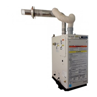
Instantaneous oil-fired water heater
Hide thumbs
Also See for Oil Miser OM-148:
- Installation manual (30 pages) ,
- Operation and maintenance instructions (16 pages) ,
- Operation and maintenance instructions (16 pages)
Table of Contents
Advertisement
Quick Links
Download this manual
See also:
Installation Manual
Instantaneous Oil-Fired Water Heater
IMPORTANT
THIS APPLIANCE SHOULD BE INSTALLED BY A LICENSED, AUTHORIZED PERSON(S) DUE TO THE
NECESSITY OF MAKING ELECTRICAL, WATER AND FUEL CONNECTIONS. RETAIN THIS MANUAL FOR
FUTURE REFERENCE. CHECK LOCAL CODES AND ORDINANCES FOR PERMITTED USE.
CAUTION
THIS WATER HEATER SHALL NOT BE USED FOR COMMERCIAL USE OR FOR ANY PURPOSES OTHER
THAN HOT WATER SUPPLY USES. OTHER USAGE MAY CAUSE A MALFUNCTION OR SHORTEN ITS
SERVICE LIFE. DO NOT REMOVE THE RATING PLATE AND LABELS FROM THE WATER HEATER UNIT.
Safety Tips for Installation ⋯⋯⋯⋯⋯⋯⋯⋯⋯⋯ 1
Unpacking ⋯⋯⋯⋯⋯⋯⋯⋯⋯⋯⋯⋯⋯⋯⋯⋯⋯ 2
Standard Installation Parts ⋯⋯⋯⋯⋯⋯⋯⋯⋯⋯ 2
Accessory Parts ⋯⋯⋯⋯⋯⋯⋯⋯⋯⋯⋯⋯⋯⋯⋯ 2
Dimensional Outline⋯⋯⋯⋯⋯⋯⋯⋯⋯⋯⋯⋯⋯ 3
Selecting a Location ⋯⋯⋯⋯⋯⋯⋯⋯⋯⋯⋯ 4
Tools Needed for Installation ⋯⋯⋯⋯⋯⋯⋯ 4
Fuel Tank Installation ⋯⋯⋯⋯⋯⋯⋯⋯⋯⋯⋯ 5
Removing Air Trap ⋯⋯⋯⋯⋯⋯⋯⋯⋯⋯⋯⋯ 6
Installation Manual
OM-148
MODEL
(Type D)
CONTENTS
Temperature and Pressure Relief
Valve Installation ⋯⋯⋯⋯⋯⋯⋯⋯⋯⋯⋯ 6
Permanent Wiring Installation ⋯⋯⋯⋯⋯⋯⋯ 6
Plumbing ⋯⋯⋯⋯⋯⋯⋯⋯⋯⋯⋯⋯⋯⋯⋯⋯ 7
Preparation ⋯⋯⋯⋯⋯⋯⋯⋯⋯⋯⋯⋯⋯⋯⋯ 12
Operation ⋯⋯⋯⋯⋯⋯⋯⋯⋯⋯⋯⋯⋯⋯⋯⋯ 12
Chimney Installation ⋯⋯⋯⋯⋯⋯⋯⋯⋯⋯⋯⋯ 13
Advertisement
Table of Contents

Related Manuals for Toyotomi Oil Miser OM-148


Summary of Contents for Toyotomi Oil Miser OM-148
-
Page 1: Table Of Contents
Instantaneous Oil-Fired Water Heater Installation Manual OM-148 MODEL (Type D) IMPORTANT THIS APPLIANCE SHOULD BE INSTALLED BY A LICENSED, AUTHORIZED PERSON(S) DUE TO THE NECESSITY OF MAKING ELECTRICAL, WATER AND FUEL CONNECTIONS. RETAIN THIS MANUAL FOR FUTURE REFERENCE. CHECK LOCAL CODES AND ORDINANCES FOR PERMITTED USE. CAUTION THIS WATER HEATER SHALL NOT BE USED FOR COMMERCIAL USE OR FOR ANY PURPOSES OTHER THAN HOT WATER SUPPLY USES. -
Page 2: Section A
SECTION A: SAFETY TIPS FOR INSTALLATION BE SURE TO FOLLOW THE FOLLOWING INSTRUCTIONS. The instructions which are contained in this manual are classified into the following two types, which are "WARNING" and "CAUTION". These instructions are intended to provide important information for safe operation. -
Page 3: Section B
SECTION B: UNPACKING UNPACKING Unpack the unit carefully. Check to see if there are any loose screws that may have occurred in transit. Take accessories and the instruction manual out of the carton. STANDARD INSTALLATION PARTS The following standard installation kits are available: •... -
Page 4: Dimensional Outline
DIMENSIONAL OUTLINE Hot water Supply 5-1/8" 5-1/8" Outlet (130mm) (130mm) (NPT 3/4) Male Water Supply Inlet (NPT 3/4) Male 3/16" (5mm) Air Intake Inlet Exhaust Outlet 2-3/4"( 70mm) 2-3/4"( 70mm) 12-5/8"(320mm) Access Cover Temperature and Pressure Relief Valve Installation Opening (NPT 3/4) Female Front Panel Junction Box... -
Page 5: Section C
SECTION C: INSTALLATION WARNING: This unit must be installed in accordance with these instructions, local codes, ordinances and/or in the absence of local codes, the latest edition of the national fire protection association (NFPA31) code. Check and comply with all state, local codes and ANSI (AMERICAN NATIONAL STANDARD INSTITUTE) Z21.22 that may apply to water heater(s) before beginning the installation. -
Page 6: Fuel Tank Installation
FUEL TANK INSTALLATION The fuel tank must be purchased separately and installed by a qualified fuel supply technician. NOTE: Fuel tank installation must comply with National Fire Protection Association Code NFPA 31 or local- ly applicable codes. Check with local building officials. The following instructions should be followed for installation of a large capacity, gravity-fed fuel tank. -
Page 7: Removing Air Trap
REMOVING AIR TRAP When operating for the first time or when refueling an empty tank, air may be trapped in the fuel line, mak- ing ignition difficult. In this situation, after removing the trapped air thoroughly from the fuel filter at the fuel tank outlet, follow the procedures below: Press "POWER SWITCH"... -
Page 8: Plumbing
BE SURE TO FOLLOW THE FOLLOWING PROCEDURE POWER SOURCE: 120V AC, 60Hz single phase Disconnect power supply cord from power source. Remove four (4) screws and junction box cover on the left side of unit. Disconnect ground wire (green) from the power supply cord bracket. - Page 9 Use standard copper alloy unions and nipples for the connections to the unit. Copper piping is recommended for the hot water supply line. Note: Refer to local codes when considering piping materials. Steel piping is not recommended as it may cause rust in the piping. Use NPT for piping of hot and cold water. Connecting plumbing to the unit, hold unit fittings securely with a wrench to prevent damage to the unit.
-
Page 10: Installation Of Unit And Flue Pipe
INSTALLATION OF THE UNIT AND FLUE PIPE SAFETY TIPS WARNING: The flue pipe opening must be fully exposed to outside air. Do not vent into a garage, basement, under the floor, or into any enclosed area. Do not install the flue pipe in close proximity to other objects or materials. Before making a hole in your wall for the flue pipe, make sure the area is free of electrical wires, gas pipes and other obstacles. - Page 11 INSTALLATION OF FLUE PIPE IMPORTANT: Check and comply with all state and local codes that may apply to water heater before begin- ning installation. Select unit location. Allow clearances as indicated above between the unit and all other materials Make sure that the outside area to where the flue pipe will reach is clear of any objects. NOTE: For wall thickness greater than 10-1/2 inches, a flue pipe extension is available.
- Page 12 Slide the insulating cloth cover over the flexible exhaust pipe and the flexible bent joint. Insulating cloth cover Remove the screw from the exhaust opening of the unit. Insert the flexible exhaust pipe to the exhaust opening and secure them with the screw. NOTE: Seal all connections of the pipes with the aluminum tape.
-
Page 13: Section D
0- /2 in. (270 mm) maximum Inner flue pipe Hose band Rubber joint Flange gasket 4~ 0- /2 in. ( 00~270 mm) Insulating cloth cover Outer flue pipe Flexible bent joint Tight band Inner sleeve flange Inlet hose Rubber joint Aluminum tape Flexible exhaust pipe Hose band... -
Page 14: Section E
SECTION E: CHIMNEY INSTALLATION This unit is a sealed combustion system and as an installation option it may be connected directly to a chimney. Using this option, room air is used for combustion and the exhaust gases are vented into the chimney to the outside. IMPORTANT: This appliance should be installed by a licensed, authorized person(s) due to necessity of making electrical, water and fuel connections. - Page 15 Installation of Chimney Example Chimney Liner Intake Air Outlet Opening Chimney Exhaust Pipe (Dia. = 5 inch/4 inch) Heat-Resistand Barometric Sealing Matrials Draft Regulator (UL-listed) Outside Intake Pipe Top Exhaust Pipe Adapter Outside Air Intake Opening OM-148 Fig. 1 INSTALLATION OF EXHAUST PIPE ADAPTER Remove the screw from the exhaust outlet of the unit.
- Page 16 TOYOTOMI U.S.A., INC. 604 Federal Road, Brookfield, CT 06804 www.toyotomiusa.com This manual supersedes earlier editions. PART No.20476691 Printed in Japan Rev. 3/09 4731003052...