Toyotomi Oil Miser OM-180 Installation Manual
Instantaneous oil-fired water heater
Hide thumbs
Also See for Oil Miser OM-180:
- Installation manual (20 pages) ,
- Operation & maintenance instructions manual (16 pages) ,
- Operation and maintenance instructions (16 pages)
Table of Contents
Advertisement
Quick Links
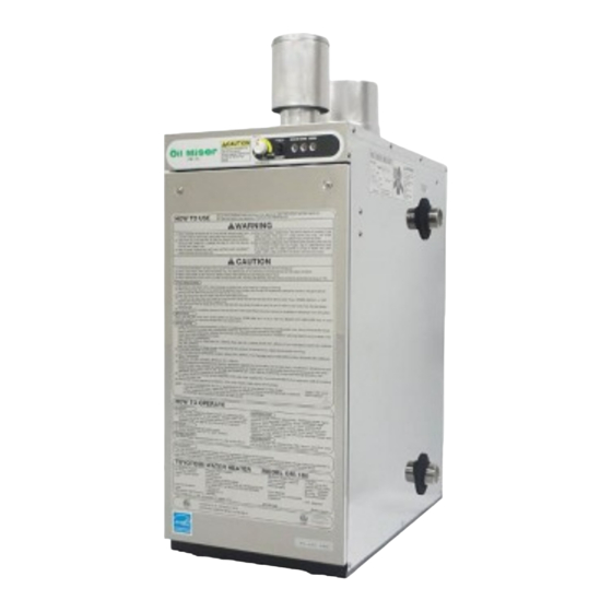
Instantaneous Oil-Fired Water Heater
IMPORTANT
THIS APPLIANCE SHOULD BE INSTALLED BY A LICENSED, AUTHORIZED PERSON(S) DUE TO THE
NECESSITY OF MAKING ELECTRICAL, WATER AND FUEL CONNECTIONS. RETAIN THIS MANUAL FOR
FUTURE REFERENCE. CHECK LOCAL CODES AND ORDINANCES FOR PERMITTED USE.
CAUTION
THIS WATER HEATER SHALL NOT BE USED FOR COMMERCIAL USE OR FOR ANY PURPOSES OTHER
THAN HOT WATER SUPPLY USES. OTHER USAGE MAY CAUSE A MALFUNCTION OR SHORTEN ITS
SERVICE LIFE. DO NOT REMOVE THE RATING PLATE AND LABELS FROM THE WATER HEATER UNIT.
Temperature and Pressure Relief
Installation Manual
OM-180
MODEL
CONTENTS
1
2
2
2
3
4
4
5
6
6
7
9
10
10
11
12
15
15
16
Advertisement
Table of Contents

Related Manuals for Toyotomi Oil Miser OM-180


Summary of Contents for Toyotomi Oil Miser OM-180
-
Page 1: Table Of Contents
Instantaneous Oil-Fired Water Heater Installation Manual OM-180 MODEL IMPORTANT THIS APPLIANCE SHOULD BE INSTALLED BY A LICENSED, AUTHORIZED PERSON(S) DUE TO THE NECESSITY OF MAKING ELECTRICAL, WATER AND FUEL CONNECTIONS. RETAIN THIS MANUAL FOR FUTURE REFERENCE. CHECK LOCAL CODES AND ORDINANCES FOR PERMITTED USE. -
Page 2: Section A
SECTION A: SAFETY TIPS FOR INSTALLATION BE SURE TO FOLLOW THE FOLLOWING INSTRUCTIONS. The instructions which are contained in this manual are classified into the following two types, which are "WARNING" and "CAUTION". These instructions are intended to provide important information for safe operation. -
Page 3: Section B
SECTION B: UNPACKING UNPACKING Unpack the unit carefully. Check to see if there are any loose screws that may have occurred in transit. Take accessories and the instruction manual out of the carton. STANDARD INSTALLATION PARTS The following standard installation kits are available: •... -
Page 4: Dimensional Outline
DIMENSIONAL OUTLINE 3/16” (5mm) Air Intake Inlet Exhaust Outlet ø2-3/4”(ø70mm) ø2-3/4”(ø70mm) 12-5/8” (320mm) Access Cover Hot Water Outlet or T&P Relief Valve (NPT 1-1/4”Male) Front Panel Cold Water Inlet or Drain Outlet (NPT 1-1/4” Male) Fuel Line Junction Box... -
Page 5: Section C
SECTION C: INSTALLATION WARNING: This unit must be installed in accordance with these instructions, local codes, ordinances and/or in the absence of local codes, the latest edition of the national fire protection association (NFPA31) code. Check and comply with all state, local codes and ANSI (AMERICAN NATIONAL STANDARD INSTITUTE) Z21.22 that may apply to water heater(s) before beginning the installation. -
Page 6: Fuel Tank Installation
FUEL TANK INSTALLATION The fuel tank must be purchased separately and installed by a qualified fuel supply technician. NOTE: Fuel tank installation must comply with National Fire Protection Association Code NFPA 31 or local- ly applicable codes. Check with local building officials. The following instructions should be followed for installation of a large capacity, gravity-fed fuel tank. -
Page 7: Removing Air Trap
REMOVING AIR TRAP When operating for the first time or when refueling an empty tank, air may be trapped in the fuel line, mak- ing ignition difficult. In this situation, after removing the trapped air thoroughly from the fuel filter at the fuel tank outlet, follow the procedures below: Press "POWER SWITCH"... -
Page 8: Plumbing
WARNING: Plumbing should conform to proper plumbing methods, and in conformance with local codes or regulations. A licensed plumber familiar with local codes and ordinances should install the OM-180. CAUTION: An ANSI (AMERICAN NATIONAL STANDARD INSTITUTE) listed temperature and pressure relief valve should be installed at the hot water outlet connection of the heater at the time of installation. - Page 9 Install heat insulation material on the hot water piping to prevent heat loss. In closed systems we recommend the use of an antifreege solution to prevent freezing and corrosion. Check with the plumbing installer for the proper mix. Copper or stainless steel or cross-linked polyethylene pipe should be used for the main and branch pipes. Be sure to connect a hot water pipe with the Expansion Tank, and install at the inlet side of the Circulation Pump.
- Page 10 Plumbing Example (For Heating) Air release valve Circulation pump Temperature Header and pressure relief valve Header valve Hot water Expantion Outlet tank Bypass Union Differential Pressure relief valve Pressure valve Air release valve Valve Hot water Inlet Header valve Drain Header Air separator Water supply valve...
-
Page 11: Permanent Wiring Installation
PERMANENT WIRING INSTALLATION WARNING: TO AVOID ANY RISK OF FIRE AND ELECTRIC SHOCK. Make sure the main circuit breaker and power supply cord is disconnected before servicing. Electric shock may cause serious injury. It is recommended that installation should be conducted by a Licensed Electrician. PROCEDURE FOR PERMANENT WIRING POWER SOURCE: 120V AC, 60Hz single phase Turn off the main circuit breaker. -
Page 12: Differential Switch And Dip Switch
DIFFERENTIAL SWITCH AND DIP SWITCH NOTE: Make sure that the power supply cord is disconnected when changing the position of DIP Switch is selected. The differential switch on the main circuit board controls does not change the heat exchanger water temper- ature. -
Page 13: Wiring For Timer
Connect to the circulation pump using the attached coupler. See the wiring diagram below for wiring to the circuit board. How to use the coupler Make 3/16 in. (4-5mm) space. Lead wire for circulation pump Circulation pump Stopper (available on the market) Power lead wire of the external circulation pump... -
Page 14: Installation Of Unit And Flue Pipe
INSTALLATION OF THE UNIT AND FLUE PIPE SAFETY TIPS WARNING: The flue pipe opening must be fully exposed to outside air. Do not vent into a garage, basement, under the floor, or into any enclosed area. Do not install the flue pipe in close proximity to other objects or materials. Before making a hole in your wall for the flue pipe, make sure the area is free of electrical wires, gas pipes and other obstacles. - Page 15 INSTALLATION OF FLUE PIPE IMPORTANT: Check and comply with all state and local codes that may apply to water heater before begin- ning installation. Select unit location. Allow clearances as indicated above between the unit and all other materials Make sure that the outside area to where the flue pipe will reach is clear of any objects. NOTE: Make sure wall thickness is not greater than 10-1/2 inches.
- Page 16 Slide the insulating cloth cover over the flexible exhaust pipe and the flexible bent joint. Insulating cloth cover NOTE: When disconnecting the extension pipe (such as flexible pipe and flexible bent joint), turn clockwise and pull apart. Remove the screw from the exhaust opening of the unit. Insert the flexible exhaust pipe to the exhaust opening and secure them with the screw.
-
Page 17: Section D
10-1/2 in. (270 mm) maximum Inner flue pipe Hose band Rubber joint Flange gasket 4~10-1/2 in. (100~270 mm) Insulating cloth cover Outer flue pipe Flexible bent joint Tight band Inner sleeve flange Inlet hose Rubber joint Aluminum tape Flexible exhaust pipe Hose band Exhaust pipe ring SECTION D:... -
Page 18: Section E
In case another appliance is connected to the same chimney flue (2 or more units), it may be necessary to comply with state and local codes. Connecting the OM-180 hot water heater with two or more appliances using the same chimney flue may affect the performance of the hot water heater. - Page 19 Intake Pipe Top Exhaust Pipe Adapter Outside Air Intake Opening (more than155 in OM-180 Fig. 1 INSTALLATION OF EXHAUST PIPE ADAPTER Exhaust Outlet Remove the screw from the exhaust outlet of the unit. Insert the exhaust pipe adapter to the exhaust outlet and secure with the screw.
- Page 20 TOYOTOMI U.S.A., INC. 604 Federal Road, Brookfield, CT 06804 www.toyotomiusa.com This manual supersedes earlier editions. PART No.20476787 Printed in Japan Rev. 6/11 4788003052...