Table of Contents
Advertisement
INSTALLATION AND SERVICE MANUAL
WARNING: Do not use
this appliance if any part
has been under water. The
possible
damage
flooded appliance can be
extensive
and
numerous safety hazards.
Any appliance that has
been under water must be
replaced.
HYDRONIC HEATING BOILERS and
DOMESTIC WATER HEATERS
495,000 - 2,065,000 Btu/hr MODELS
WARNING: Improper
installation,
alteration,
maintenance can cause
property damage, personal
injury,
hazardous
loss of life. Refer to this
manual. Installation and
service must be performed
to
a
by a qualified installer,
service agency or the gas
present
supplier. This unit contains
materials that have been
identified as carcinogenic,
or possibly carcinogenic,
to humans.
Save this manual for future reference.
adjustment,
service
or
exposure
to
materials
or
CB-CW(E)-i&s-06
WARNING:
information in this manual
is not followed exactly, a
fire
or
explosion
result causing property
damage, personal injury or
loss of life.
– Do not store or use
gasoline
or
flammable
vapors
liquids in the vicinity of
this or any other appliance.
WHAT TO DO IF YOU SMELL
GAS
• Do not try to light any
appliance.
• Do
not
touch
electric switch; do not
use any phone in your
building.
• Immediately call your
gas supplier from a
neighbors
Follow
the
supplier's instructions.
• If you cannot reach your
gas supplier, call the fire
department.
– Installation and service
must be performed by a
qualified installer, service
agency or the gas supplier.
If
the
may
other
and
any
phone.
gas
Advertisement
Table of Contents

Related Manuals for Lochinvar 000 - 2


Summary of Contents for Lochinvar 000 - 2
-
Page 1: Domestic Water Heaters
INSTALLATION AND SERVICE MANUAL HYDRONIC HEATING BOILERS and 495,000 - 2,065,000 Btu/hr MODELS WARNING: Do not use this appliance if any part has been under water. The possible damage flooded appliance can be extensive present numerous safety hazards. Any appliance that has been under water must be replaced. -
Page 2: Table Of Contents
Hydronic Heating Boilers and Domestic Water Heaters Table of Contents General Product Information ......3 Special Instructions ......3 Unpacking . -
Page 3: General Product Information
GENERAL PRODUCT INFORMATION Special Instructions This manual supplies information for the installation, operation and servicing of the appliance. Read and understand this manual completely before installing unit. Installation and service must be performed by a qualified service installer, service agency, or the gas supplier. Unpacking Upon receiving equipment, check for signs of shipping damage. - Page 4 Hydronic Heating Boilers and Domestic Water Heaters 3. Boilers and water heaters are heat producing appliances. To avoid damage or injury, do not store materials against the appliance or the vent-air intake system. Use proper care to avoid unnecessary contact (especially children) with the appliance and vent-air intake components.
-
Page 5: Product Identification
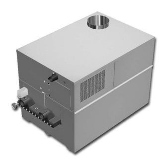
Installation and Service Manual PRODUCT IDENTIFICATION Front View Rear View Figure 1 – Front and Rear View... -
Page 6: Installation
Figure 2 - Clearances from Combustible Construction Base for Combustible Floors There is no manufactured combustible floor base kit available for 985,000 - 2,065,000 Btu/hr models. You must construct a 3" (7.5 cm) 3" (7.5 cm) (3" min. from any surface) 6"... -
Page 7: Freeze Protection
base for combustible floor installation. Install unit over a base of hollow clay tiles or concrete blocks from 8" to 12" thick and extending at least 24" beyond the unit sides. Place tiles or blocks so that the holes line up horizontally to provide a clear passage through the tiles or blocks. -
Page 8: Freeze Protection For A Heating Boiler System
Combustion Air Filter The 985,000 - 2,065,00 Btu/hr models have a standard air filter(s) located behind the combustion air inlet panel(s). This filter helps ensure clean air is used for the combustion process. -
Page 9: Combustion Air Options
Combustion Air Options CAUTION: Under should the mechanical room ever be under a negative pressure. Particular care should be taken where exhaust fans, attic fans, clothes dryers, compressors, air handling units, etc., take away air from the unit. 1. Outside Combustion Air, No Ducts You can direct outside combustion air to this unit using either one or two permanent openings. -
Page 10: Exhaust Fans
Hydronic Heating Boilers and Domestic Water Heaters INSTALLATION Continued Figure 9 - Combustion Air from Interior Space All dimensions are based on net free area in square inches. Metal louvers or screens reduce the free area of a combustion air opening a minimum of approximately 25%. Check with louver manufacturers for exact net free area of louvers. - Page 11 You must locate the air inlet termination elbow at least 12" (30cm) above the roof or above normal snow levels. Keep the vent cap clear of snow, ice, leaves, and debris to avoid blocking the flue. Figure 10 - Vent Termination from Peaked Roof - 10' or Less From Ridge IMPORTANT: Vent terminations are not shown in Figures 10, 11, 12, and 13.
-
Page 12: Vent System Options
Hydronic Heating Boilers and Domestic Water Heaters INSTALLATION Continued TABLE - B Flue Pipe Sizes Input Flue Btu/hr Size 495,000 6" 645,000 8" 745,000 8" 985,000 10" 1,255,000 12" 1,435,000 12" 1,795,000 14" 2,065,000 14" Vent System Options This unit has two venting options. 1. -
Page 13: Conventional Negative Draft Venting
1. Conventional Negative Draft Venting IMPORTANT: Before installing a venting system, follow all venting clearances and requirements found in the Venting, General Information section, page 10. Figure 14 - Conventional Negative Draft Vertical Venting with Combustion Air Louvers This option uses Type-B double-wall flue outlet piping. The blower brings in combustion air. -
Page 14: Outdoor Installation Venting
Hydronic Heating Boilers and Domestic Water Heaters INSTALLATION Continued 4. Turn on clothes dryers and any other appliances not connected to the common venting system. Turn on any exhaust fans, such as range hoods and bathroom exhausts, so they will operate at maximum speed. Do not operate a summer exhaust fan. - Page 15 Outdoor Vent/Air Inlet Location Keep venting areas free of obstructions. Keep area clean and free of combustible and flammable materials. Maintain a minimum clearance of 3" (76mm) to combustible surfaces and a minimum of 3" (76mm) clearance to the air inlet. To avoid a blocked air inlet or blocked flue condition, keep the air inlet, flue outlet and drain slot clear of snow, ice, leaves, debris, etc.
-
Page 16: Connecting To Gas Supply
4.5" w.c. 8" w.c. Figure 17 - 495,000 - 745,000 Btu/hr Gas Line Connection Example Figure 18 - 985,000 - 2,065,000 Btu/hr Gas Line Connection Example IMPORTANT: Do not block access to the electrical cover plate when installing the sediment trap. The sediment trap must be a... -
Page 17: Connecting Gas Piping To Unit
The combination gas valves have an integral vent limiting device and does not require venting to atmosphere outside the building. The unit will not operate properly if the reference hose is removed or a vent to atmosphere is installed. Optional gas controls may require routing of bleeds and vents to the atmosphere outside the building when required by local codes. -
Page 18: Combination Gas Valves
Domestic Water Heaters INSTALLATION Continued Water heater models do not have downstream test valves, but the rest of the gas train is represented by Figure 19. Combination Gas Valves These units fire in up to 2 stages of burner input. Each stage of... -
Page 19: Gas Manifold Pressure Adjustment
9. If gas pressure is out of range, contact your gas utility, gas supplier, qualified installer or service agency to determine the necessary steps to provide proper gas pressure to the control. 10. If gas supply pressure is within normal range, remove the gas manometer and replace the pressure tap fittings in the gas control as indicated in the following steps. -
Page 20: Connecting To Water Supply
TABLE - I NET MANIFOLD PRESSURE Regulator Pressure Less Front Chamber Pressure Nat. Gas (495,000 - 745,000 Btu/hr) Nat. Gas (985,000 - 2,065,000 Btu/hr) LP Gas (495,000 - 2,065,000 Btu/hr) TABLE-H CONNECTING TO WATER SUPPLY Inlet and Outlet Connections For ease of service, install unions on the water inlet and water outlet of the unit. -
Page 21: Relief Valve
Figure 22 - Water Connections Relief Valve This unit is supplied with a relief valve(s) sized in accordance with ASME Boiler and Pressure Vessel Code, Section IV ("Heating Boilers"). The relief valve(s) is installed in the vertical position and mounted in the hot water outlet. Place no other valve between the relief valve and the unit. -
Page 22: Terminal Strip Connection Options
2,065,000 Figure 23A - Models 495,000 - 745,000 Btu/hr Control Panel Component Location Drawing Figure 23B - Models 985,000 - 2,065,000 Btu/hr Control Panel Component Location Drawing IMPORTANT: Do not block access to the electrical cover plate when installing electrical conduit. -
Page 23: Boiler System Piping
Figure 24B - Remote On/Off Boiler or Water Heater - Models 985,000 - 2,065,000 Btu/hr Only Figure 24C - Two-Stage (High/Low Fire) Boiler or Water Heater - Models 985,000 - 2,065,000 Btu/hr Only Figure 24D - Field-Installed Safety Devices - Models 985,000 - 2,065,000 Btu/hr Only... -
Page 24: Primary/Secondary Boiler Piping
Hydronic Heating Boilers and Domestic Water Heaters INSTALLATION Continued Circulator Pump Requirements This is a low mass, high efficiency hot water boiler which must have adequate flow for quiet, efficient operation. selection is critical to achieve proper operation. A pump should be selected to achieve proper system design water temperature rise. -
Page 25: Low Temperature Return Water Systems
Systems Any non-condensing boiler and venting system will develop operational problems when exposed to inlet water temperatures below 140°F. Lochinvar offers a low Installation and Service Manual temperature protection valve (LTV) that is factory preset to maintain 140°F inlet water to the boiler regardless of the system return water temperature. -
Page 26: Installation With A Chilled Water System
Hydronic Heating Boilers and Domestic Water Heaters INSTALLATION Continued Sludge formed as the result of excessive oxygen in the system can restrict water flow resulting in a premature boiler failure. Any boiler damage due to excessive oxygenation is non- warrantable. Figure 28 - Boiler with Low Temperature Bypass Piping System Temperature Rise Chart Based on Btu/hr Input System Temperature Risased on Btu/hr Input... -
Page 27: Boiler Flow Rate
Boiler Flow Rate CAUTION: The maximum flow rate for models 495,000 - 745,000 Btu/hr is 60 GPM and 90 GPM on 985,000 - 2,065,000 models. Do not exceed the maximum flow rate of the heating boiler. If higher flow rates are required through the boiler, an optional Cupro-Nickel heat exchanger is available. -
Page 28: Water Treatment
Hydronic Heating Boilers and Domestic Water Heaters INSTALLATION Continued 8. Recheck all air vents as described in step 4. 9. Inspect the liquid level in the expansion tank. The system must be full and under normal operating pressure to ensure proper water level in the expansion tank. -
Page 29: To Turn Off Gas To Appliance
Figure 31 - Control Panel Cover Figure 32 - ON/OFF Switch 8. Turn the manual gas cock clockwise to the “OFF” position. 9. Wait five (5) minutes to clear out any gas. If you smell gas, STOP! Follow “B” in the safety information. If you do not smell gas, go on to the next step. -
Page 30: Temperature Control Settings
Hydronic Heating Boilers and Domestic Water Heaters OPERATION Continued Figure 34 - Locating Temperature Control Temperature Control Settings There are three setting knobs on the temperature control unless your unit is specified as a boiler only with an outdoor air reset option. -
Page 31: Outdoor Air Reset Option
High-Fire Offset The temperature control operates a two-stage firing system. The two stages are High-Fire and Low-Fire. High-Fire operates all burners while Low-Fire operates approximately one-half of the burners. The High-Fire knob specifies the number of degrees below set point that the High-Fire stage shuts down. At that point, the unit will continue to operate at the Low-Fire stage until the set point is reached. -
Page 32: Temperature Control Sensors
Boilers with the outdoor air reset option also have an outside air temperature sensor. Water Heater Application Water heater units are shipped with two sensors; the inlet water temperature sensor and the multi-purpose temperature sensor to be used as a tank sensor. -
Page 33: Remote Mounting Of Sensor
Figure 38 - Hot Surface Igniter Caution: The igniter is extremely fragile, be very careful when removing. A faulty or damaged hot surface igniter MUST BE replaced with a Lochinvar PLT3400 igniter. Do not use general purpose field replacement igniters. - Page 34 Hydronic Heating Boilers and Domestic Water Heaters OPERATION Continued Hot Surface Ignition Control Module Ignition Module Lockout Functions The ignition module may lockout in either a hard-lockout condition, requiring pushing of the reset button to recycle the control, or a soft-lockout condition which may recycle after an approximate five-minute waiting period.
-
Page 35: Operation And Diagnostic Lights
Status ignition module. Alarm Indicates flame failure on the ignition module and will indicate additional alarms if the alarm of any failure option is purchased. Models 495,000 - 745,000 Btu/hr Models 985,000 - 2,065,000 Btu/hr Figure 40 - Operation/Diagnostic Lights... -
Page 36: Domestic Water Heaters
1. With the pump running and the water heater off, the inlet and outlet thermometers should read the same temperatures. If they do not, an adjustment must be made to your final calculation. -
Page 37: Water Chemistry
Units Circulating Pump EXPANSION TANK (IF REQUIRED) 1. The water heater must be connected to a properly sized pump that circulates water between the heater and storage tank. CIRCULATING 2. The pump is sized to heater input and water hardness. Care PUMP should be taken to size the pump correctly. -
Page 38: Minimum Pump Performance
120°F (49°C) or lower temperature hot water to reduce risk of scald injury. Operate this high efficiency hot water heater at a temperature setting high enough to prevent condensing of the products of combustion on the unit's heat exchanger or in the attached venting system. -
Page 39: Location Of Cold Water Supply Piping Connections
5. Stage firing can be achieved by adjusting the High-Fire Offset to any value other than zero. Typically, a setting of 3°F is 5°F is suitable for stage firing in a water heater application. Stage firing of a potable water heater is normally only used to replace system standby heat loss. -
Page 40: Cleaning And Maintenance
Hydronic Heating Boilers and Domestic Water Heaters CLEANING AND MAINTENANCE Listed below are items that must be checked to ensure safe reliable operations. Verify proper operation after servicing. CAUTION: Label all wires prior to disconnection when servicing controls. Wiring errors can cause improper and dangerous operation. -
Page 41: Heat Exchanger Cleaning
Heat Exchanger Cleaning 1. While burners are removed, check the heat exchanger surface for sooting. If present, heat exchanger must be cleaned and problem corrected. Proceed as follows. 2. Remove gas manifold(s)/orifice assemblies as described in steps 1 through 5 in Burner Removal and Cleaning, page 3. - Page 42 Hydronic Heating Boilers and Domestic Water Heaters CLEANING AND MAINTENANCE Figure 43 - Air Pressure Switch Turn the adjustment screw on the air shutter to open or close shutter. Figure 44 - Adjusting Air Shutter Set Up Procedure To the left of the fan is an air pressure switch with a large and a small tube delivering pressure from points inside the unit (see Figure 43).
-
Page 43: Servicing Hot Surface Igniter And Ignition Module
Adjustment Procedure: 1,435,000, 1,795,000 and 2,065,000 Btu/hr Models 1. Remove the upper front jacket panels from the unit to access the upper chamber. 2. Slightly loosen the screws that attach the fan transition box to the metal base (see Figure 46). 3. -
Page 44: Ignition System Checkout
22. After a time delay of 10 seconds, the remaining gas valves on the 985,000 - 2,065,000 Btu/hr models open, supplying gas to the remaining burners. 23. The gas/air mixture is forced out of the burners and out of the burner ports under pressure. -
Page 45: Glossary
(yellow) is connected to chassis ground. 24VAC Circuit Breaker A circuit breaker is provided on the 985,000 - 2,065,000 Btu/hr models for protection of the low voltage supply transformer from overloads and short circuits. The breaker is located inside the unit on the lower right corner of the control panel. - Page 46 (Controlled by Electronic Temperature Controller and Ignition Module) A small relay board is provided on the 985,000 - 2,065,000 Btu/hr models to switch the blower from low to high speed and to deliver power from the low fire stage (Stage 1) to the high fire stage (Stage 2) depending upon the electronic thermostat's settings.
-
Page 47: Schematic/Wiring Diagrams
SCHEMATIC DIAGRAM MODELS 495,000 - 745,000 BTU/HR CONTACTS VENTER LOUVER- OPTIONAL O.C. 24VCOM 24 GND... - Page 48 WIRING DIAGRAMS - MAIN UNIT CONNECTIONS MODELS 495,000 - 745,000 BTU/HR...
- Page 49 WIRING DIAGRAMS - MAIN UNIT CONNECTIONS MODELS 495,000 - 745,000 BTU/HR (CONTINUED) 24 VAC LOW VOLTAGE XFMR. TEST SILENCE NORMALLY CLOSED BR/W LOUVER /DAMPER 120 VAC RELAY SPLICE CHASSIS GROUND SPLICE SPLICE SPLICE BURNER GROUND VALVE #1 HOT SURFACE IGNITER MAIN UNIT - GAS VALVES - BLOWER PRESSURE SWITCH OA SENSOR OPERATOR...
- Page 50 SCHEMATIC AND WIRING DIAGRAM MODELS 985,000 - 2,065,000 BTU/HR GROUND CHASSIS BREAKER CIRCUIT...
- Page 51 WIRING DIAGRAM - CONTROL BOX CONNECTIONS MODELS 985,000 - 2,065,000 BTU/HR ADDED ALARM UNLESS CONNECTED 120V 24VAC XFMR.
- Page 52 Revision 4 (CB-CW(E)-i&s-04) reflects changes made to the O.A. section. Revision 5 (CB-CW(E)-i&s-05) reflects changes made to text on Page 21 and the LBLs on pages 47-51. Revision 6 (ECO #C02870) reflects the addition of a mixing valve to FIG. 41 (page 37) and edits made to the scald warnings.