Table of Contents
Advertisement
Advertisement
Table of Contents

Related Manuals for Asus M2NPV-VM


Summary of Contents for Asus M2NPV-VM
- Page 1 M2NPV-VM...
- Page 2 Product warranty or service will not be extended if: (1) the product is repaired, modified or altered, unless such repair, modification of alteration is authorized in writing by ASUS; or (2) the serial number of the product is defaced or missing.
-
Page 3: Table Of Contents
Contents Notices......................vi Safety.information..................vii M2NPV-VM specifications summary............x Chapter 1: Product introduction Special features................1-2 1.1.1 Product highlights ............1-2 1.1.2 Innovative ASUS features ..........1-4 Before you proceed..............1-5 1.3. Motherboard.overview..............1-6 1.3.1... - Page 4 ASUS EZ Flash utility ............2-5 2.1.4 Updating the BIOS ............2-6 2.1.5 Saving the current BIOS file ..........2-8 2.1.6 ASUS CrashFree BIOS 2 utility ........2-9 BIOS setup program..............2-10 2.2.1 BIOS menu screen ............2-11 2.2.2 Menu bar ................2-11 2.2.3...
- Page 5 Contents Power menu................. 2-26 2.5.1 ACPI Suspend Type ............2-26 2.5.2 ACPI APIC Support ............2-26 2.5.3 APM Configuration ............2-26 2.5.4 Hardware Monitor ............2-29 Boot menu................... 2-31 2.6.1 Boot Device Priority ............2-31 2.6.2 Removable Drives ............2-31 2.6.3 Boot Settings Configuration .........
-
Page 6: Notices
Notices Federal Communications Commission Statement This device complies with Part 15 of the FCC Rules. Operation is subject to the following two conditions: • This device may not cause harmful interference, and • This device must accept any interference received including interference that may cause undesired operation. -
Page 7: Safety.information
Safety information Electrical.safety • To prevent electrical shock hazard, disconnect the power cable from the electrical outlet before relocating the system. • When adding or removing devices to or from the system, ensure that the power cables for the devices are unplugged before the signal cables are connected. If possible, disconnect all power cables from the existing system before you add a device. -
Page 8: About This Guide
Refer to the following sources for additional information and for product and software updates. ASUS.websites The ASUS website provides updated information on ASUS hardware and software products. Refer to the ASUS contact information. Optional documentation Your product package may include optional documentation, such as warranty flyers, that may have been added by your dealer. -
Page 9: Conventions Used In This Guide
Conventions used in this guide To make sure that you perform certain tasks properly, take note of the following symbols used throughout this manual. DANGER/WARNING: Information to prevent injury to yourself when trying to complete a task. CAUTION: Information to prevent damage to the components when trying to complete a task. -
Page 10: M2Npv-Vm Specifications Summary
M2NPV-VM specifications summary CPU. Support AMD socket AM2 for AMD Athlon™ 64FX/ Athlon™ 64 X2/Athlon™ 64/Sempron processors AMD64 architecture enables simultaneous 32-bit and 64-bit computing Supports AMD Cool ‘n’ Quiet™ Technology AMD Live!™ Ready ® Chipset Northbridge: NVIDIA GeForce™ 6150 GPU ®... - Page 11 Intrusion Special features ASUS Q-Fan 2 ASUS CrashFree BIOS 2 ASUS EZ Flash 1 Note: ASUS CrashFree BIOS 2 only support VGA/RGB output. BIOS features 4 Mb Flash ROM, Award BIOS, PnP, DMI2.0, WfM2.0, ACPI 2.0, SM BIOS 2.3 Rear.panel...
- Page 12 M2NPV-VM specifications summary Power Requirement ATX power supply (with 24-pin and 4-pin 12 V plugs) ATX 12 V 2.0 compliant Form.Factor uATX: 9.6 in. x 9.6 in. (24.5cm x 24.5cm) Support CD contents Device drivers AMD Cool ‘n’Quiet™ utility ASUS Update utility...
- Page 13 This chapter describes the motherboard features and the new technologies it supports. Product introduction...
-
Page 14: Special Features
Special features 1.1.1 Product highlights Latest.processor.technology.. The motherboard supports AMD socket AM2 single-core Athlon 64/ Sempron and dual-core Athlon 64 X2/Athlon 64 FX processors with 2MB/1MB/512KB L2 cache, which is based on 64-bit architecture. It features 2000/1600 MT/s HyperTransport Bus, dual-channel un-buffered DDR2 800 memory support and AMD Cool ‘n’ Quiet Technology. - Page 15 GeForce6150 chipset that supports superior HDTV-out functionality with a higher resolution to 1080i and 720p format, which are clearer than traditional formats allow. ASUS M2NPV-VM motherboard bundles a HDTV-out module that helps you enjoy the high-quality scaling and filtering technology.
-
Page 16: Innovative Asus Features
BIOS chip. See page 2-10 for details. ASUS.EZ.Flash..With the ASUS EZ Flash, you can easily update the system BIOS even before loading the operating system. No need to use a DOS-based utility or boot from a floppy disk. See page 2-6 for details. -
Page 17: Before You Proceed
ON, in sleep mode, or in soft-off mode. This is a reminder that you should shut down the system and unplug the power cable before removing or plugging in any motherboard component. The illustration below shows the location of the onboard LED. SB_PWR M2NPV-VM ® Standby Powered M2NPV-VM.Onboard.LED Power ASUS M2NPV-VM... -
Page 18: Motherboard.overview
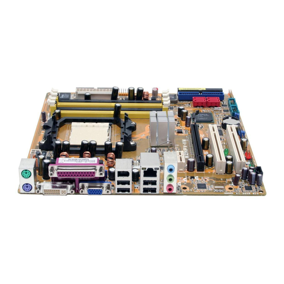
CPU_FAN ATX12V Super USBPW12 F_USB12 CHA_FAN1 LAN_USB34 USBPW34 ® nVIDIA Top:Line In GeForce™6150 Center:Line Out Bottom:Mic In TV_OUT PCIEX1_1 BIOS M2NPV-VM CHA_FAN2 PCIEX16 88E1116 ® ® nVIDIA nForce™430 PCI1 TSB43AB22A SB_PWR PCI2 CR2032 3V Lithium Cell 1986A CMOS Power USBPW78... -
Page 19: Placement Direction
1.3.3. Screw.holes Place eight (8) screws into the holes indicated by circles to secure the motherboard to the chassis. Do not overtighten the screws! Doing so can damage the motherboard. Place.this.side.towards. the.rear.of.the.chassis M2NPV-VM ® ASUS M2NPV-VM... -
Page 20: Central.processing.unit.(Cpu)
CPU! 1.4.1. Installing.the.CPU To install a CPU. Locate the CPU socket on the motherboard. M2NPV-VM ® M2NPV-VM.CPU.Socket.AM2 Unlock the socket by pressing the lever sideways, then lift it up to a 90°-100° angle. - Page 21 Connect the CPU fan cable to the CPU_FAN connector on the motherboard. CPU_FAN M2NPV-VM ® M2NPV-VM.CPU.fan.connector Do not forget to connect the CPU fan connector! Hardware monitoring errors can occur if you fail to plug this connector. ASUS M2NPV-VM...
-
Page 22: Installing The Heatsink And Fan
1.4.2. Installing.the.heatsink.and.fan The AMD Athlon™ 64/Sempron™ processor require a specially designed heatsink and fan assembly to ensure optimum thermal condition and performance. Make sure that you use only qualified heatsink and fan assembly. Follow these steps to install the CPU heatsink and fan. Place the heatsink on top of the installed CPU, making sure that the heatsink fits properly on the retention module base. - Page 23 Push down the retention bracket lock on the retention mechanism to secure the heatsink and fan to the module base. ASUS M2NPV-VM 1-11...
-
Page 24: System.memory
A DDR2 module has the same physical dimensions as a DDR DIMM but has a 240-pin footprint compared to the 184-pin DDR DIMM. DDR2 DIMMs are notched differently to prevent installation on a DDR DIMM socket. The figure illustrates the location of the DDR2 DIMM sockets: M2NPV-VM ® M2NPV-VM.240-pin.DDR2.DIMM.sockets Channel... -
Page 25: Recommended Memory Configurations
• • • 1024MB MICRON 5ZD22D9GKX MT16HTF12864AY-80ED4 • • • 512MB MICRON 6CD22D9GKX MT8HTF6464AY-80ED4 • • • 1024MB MICRON 6CD22D9GKX MT16HTF12864AY-80ED4 • • • 1024MB CORSAIR Heat-Sink Package CM2X1024-6400C4 • • • 512MB A-DATA M2OAD6G3H3160J1E52 • • ASUS M2NPV-VM 1-13... - Page 26 DDR2-800 Size Vendor .Chip.No. Part.No. DIMM. support 512MB Crucial Heat-Sink Package BL6464AA804.8FD • 1024MB Crucial Heat-Sink Package BL12864AA804.16FD • • • 256MB TwinMOS E2508AB-GE-E 8G-24IK2-EBT • • 512MB CENTURY E2508AB-GE-E 28V2S8 • • • 512MB Aeneon AET93F25DB AET660UD00-25DB98X • • •...
- Page 27 GX21GB5300SDC • • • 512MB Aeneon AET93F30DA AET660UD00-30DA98Z • • • 1024MB Aeneon AET93F30DA AET760UD00-30DA98Z • • • 1024MB UMAX U2S12D30TP-6E 53016034-7100 • • • 512MB Kingbox EPD264082200-4KI0629 • • • 1024MB Kingbox EPD264082200-4KI0629 • • • ASUS M2NPV-VM 1-15...
- Page 28 DDR2-533 Size Vendor .Chip.No. Part.No. DIMM support 256MB KINGSTON E5116AF-5C-E KVR533D2N4/256 • • • 512MB KINGSTON HYB18T512800AF37 KVR533D2N4/512 • • • 1024MB KINGSTON 5YDIID9GCT KVR533D2N4/1G • • • 512MB Qimonda HYB18T512800AC37 HYS64T64000GU-3.7-A • • • 256MB Qimonda HYB18T512160AF-3.7 HYS64T32000HU-3.7-A • •...
- Page 29 Supports one pair of modules inserted into either the yellow slots or the black slots as one pair of Dual-channel memory configuration Supports 4 modules inserted into both the yellow slots or the black slots as two pairs of Dual-channel memory configuration ASUS M2NPV-VM 1-17...
-
Page 30: Installing A Dimm
1.5.3. Installing.a.DIMM Make sure to unplug the power supply before adding or removing DIMMs or other system components. Failure to do so may cause severe damage to both the motherboard and the components. Unlock a DIMM socket by pressing DDR2.DIMM.notch the retaining clips outward. -
Page 31: Expansion.slots
Turn on the system and change the necessary BIOS settings, if any. See Chapter 2 for information on BIOS setup. Assign an IRQ to the card. Refer to the tables on the next page. Install the software drivers for the expansion card. ASUS M2NPV-VM 1-19... -
Page 32: Interrupt Assignments
Interrupt assignments Priority Standard function System Timer Keyboard Controller – Redirect to IRQ#9 IRQ Holder for PCI Steering* Communications Port (COM1)* IRQ Holder for PCI Steering* Floppy Disk Controller Printer Port (LPT1)* System CMOS/Real Time Clock IRQ Holder for PCI Steering* IRQ Holder for PCI Steering* IRQ Holder for PCI Steering* PS/2 Compatible Mouse Port*... -
Page 33: Pci Slots
PCI Express x1 slot. 1.6.5. PCI.Express.x16.slot This motherboard has supports PCI Express x16 graphic cards that comply with PCI Express specifications. The figure shows a graphics card installed on the PCI Express x16 slot. ASUS M2NPV-VM 1-21... -
Page 34: Jumpers
Hold down the <Del> key during the boot process and enter BIOS setup to re-enter data. Except when clearing the RTC RAM, never remove the cap on CLRTC jumper default position. Removing the cap will cause system boot failure! CLRTC M2NPV-VM ® Normal Clear CMOS M2NPV-VM.Clear.RTC.RAM (Default) You do not need to clear the RTC when the system hangs due to overclocking. - Page 35 (Default) (Default) USBPW78 USBPW56 M2NPV-VM ® M2NPV-VM USB device wake-up +5VSB (Default) • The USB device wake-up feature requires a power supply that can provide 500mA on the +5VSB lead for each USB port; otherwise, the system will not power up.
- Page 36 (the default is the Space Bar). This feature requires an ATX power supply that can supply at least 500 mA on the +5VSB lead, and a corresponding setting in the BIOS. KBPWR +5VSB (Default) M2NPV-VM ® M2NPV-VM.Keyboard.power.setting 1-24 Chapter 1: Product introduction...
-
Page 37: Connectors
Line In port (light blue). This port connects a tape, CD, DVD player, or other audio sources. Line Out port (lime). This port connects a headphone or a speaker. In 4- channel/ 6-channel configuration, the function of this port becomes Front Speaker Out. Microphone port (pink). This port connects a microphone. ASUS M2NPV-VM 1-25... - Page 38 Refer to the audio configuration table for the function of the audio ports in 2, 4, or 6,-channel configuration. Audio 2, 4, or 6-channel configuration Port Headset. 4-channel 6-channel 2-channel Light Blue Line In Line In Bass/Center Lime Line Out Front Speaker Out Front Speaker Out Pink...
-
Page 39: Internal Connectors
By default, the pins labeled “Chassis Signal” and “Ground” are shorted with a jumper cap. Remove the jumper caps only when you intend to use the chassis intrusion detection feature. M2NPV-VM ® CHASSIS (Default) M2NPV-VM Chassis intrusion connector ASUS M2NPV-VM 1-27... - Page 40 If any device jumper is set as “Cable-Select,” make sure all other device jumpers have the same setting. NOTE:.Orient the red markings (usually zigzag) on the IDE ribbon cable to PIN 1. M2NPV-VM ® PIN 1 M2NPV-VM.IDE.connectors 1-28 Chapter 1: Product introduction...
- Page 41 The RAID function of these connectors is set to [Disabled] by default. If you intend to create a Serial ATA RAID set using these connectors, enable the RAID.Enabled item in the NVRAID Configuration sub-menu in the BIOS. See section “2.4.6 Onboard Device Configuration” for details. ASUS M2NPV-VM 1-29...
- Page 42 Connect the S/PDIF module cable to this connector, then install the module to a slot opening at the back of the system chassis. M2NPV-VM ® SPDIF_OUT M2NPV-VM Digital audio connector The S/PDIF module is purchased separately. 1-30 Chapter 1: Product introduction...
- Page 43 The USB 2.0 module is purchased separately. Optical drive audio in connector.(4-pin.CD) These connectors allow you to receive stereo audio input from sound sources such as a CD-ROM, TV tuner, or MPEG card. M2NPV-VM ® (black) M2NPV-VM Internal audio connector ASUS M2NPV-VM 1-31...
- Page 44 The GAME/MIDI port connects a joystick or game pad for playing games, and MIDI devices for playing or editing audio files. GAME M2NPV-VM MIDI_IN J1B2 ®...
- Page 45 • If you want to connect a high-definition front panel audio module to this connector, make sure that the HD Audio item in the BIOS is set to [Enabled]. See page 2-28 for details. ASUS M2NPV-VM 1-33...
- Page 46 Connect one end of the HDTV-out cable to this connector and the other end to the TV-out module. TV_OUT M2NPV-VM ® M2NPV-VM TV out connector • RGB and TV-out can not be used simultaneously. 1-34 Chapter 1: Product introduction...
- Page 47 PSON# +5 Volts ATX12V Ground Ground Ground +5 Volts M2NPV-VM Ground Ground +12V DC +12V DC ® -5 Volts Power OK +5 Volts +5V Standby +5 Volts +12 Volts +5 Volts +12 Volts M2NPV-VM.ATX.power.connectors Ground +3 Volts ASUS M2NPV-VM 1-35...
-
Page 48: System Panel Connector
15.. System.panel.onnector.(20-1.pin.PANEL) This connector supports several chassis-mounted functions. PWR LED SPKR PANEL M2NPV-VM ® HD_LED RESET PWR BTN M2NPV-VM.System.panel.connector Requires an ATX power supply. • System power LED This 3-pin connector is for the system power LED. Connect the chassis power LED cable to this connector. -
Page 49: Chapter 2: Bios Setup
This chapter tells how to change the system settings through the BIOS Setup menus. Detailed descriptions of the BIOS parameters are also provided. BIOS setup... -
Page 50: Managing And Updating Your Bios
BIOS in the future. Copy the original motherboard BIOS using the ASUS Update or AFUDOS utilities. 2.1.1 ASUS Update utility The ASUS Update is a utility that allows you to manage, save, and update the motherboard BIOS in Windows environment. The ASUS Update utility allows you ®... - Page 51 To update the BIOS through a BIOS file: Launch the ASUS Update utility ® from the Windows desktop by clicking Start > Programs > ASUS > ASUSUpdate > ASUSUpdate. The ASUS Update main window appears. Select Update BIOS from a file option from the drop-down menu, then click Next.
-
Page 52: Creating A Bootable Floppy Disk
2.1.2 Creating a bootable floppy disk Do either one of the following to create a bootable floppy disk. DOS environment a. Insert a 1.44MB floppy disk into the drive. b. At the DOS prompt, type.format.A:/S then press <Enter>. Windows XP environment ®... -
Page 53: Asus Ez Flash Utility
2.1.3 ASUS EZ Flash utility The ASUS EZ Flash feature allows you to update the BIOS without having to go through the long process of booting from a floppy disk and using a DOS-based utility. The EZ Flash utility is built-in the BIOS chip so it is accessible by pressing <Alt>... -
Page 54: Updating The Bios
Flash Utility. Follow these instructions to update the BIOS using this utility. 1. Download the latest BIOS file from the System builder website. Rename the file to M2NPV-VM.BIN and save it to a floppy disk, CD ROM or a USB flash disk in FAT 16/12 format. - Page 55 Press <N> when the utility prompts you to save the current BIOS file. The following screen appears. The utility verifies the BIOS AwardBIOS Flash Utility for ASUS V1.17 file in the floppy disk, CD (C) Phoenix Technologies Ltd. All Rights Reserved...
-
Page 56: Saving The Current Bios File
To save the current BIOS file using the AwardBIOS Flash Utility: Follow steps 1 to 6 of the AwardBIOS Flash Utility for ASUS V1.17 previous section. (C) Phoenix Technologies Ltd. All Rights Reserved For C51PV-MCP51-M2NPV-VM-00 DATE: 04/13/2006 Press <Y>... -
Page 57: Asus Crashfree Bios 2 Utility
2.1.6 ASUS CrashFree BIOS 2 utility The ASUS CrashFree BIOS 2 is an auto recovery tool that allows you to restore the BIOS file when it fails or gets corrupted during the updating process. You can update a corrupted BIOS file using the floppy disk that contains the updated BIOS file. -
Page 58: Bios Setup Program
BIOS setup program This motherboard supports a programmable Low-Pin Count (LPC) chip that you can update using the provided utility described in section “2.1 Managing and updating your BIOS.” Use the BIOS Setup program when you are installing a motherboard, reconfiguring your system, or prompted to“Run Setup.”... -
Page 59: Bios Menu Screen
• The BIOS setup screens shown in this chapter are for reference purposes only, and may not exactly match what you see on your screen. • Visit the System builder website to download the latest BIOS information. ASUS M2NPV-VM 2-11... -
Page 60: Legend Bar
2.2.3. Legend.bar At the bottom of the Setup screen is a legend bar. The keys in the legend bar allow you to navigate through the various setup menus. The following table lists the keys found in the legend bar with their corresponding functions. Navigation Key Function <F1>... -
Page 61: Pop-Up Window
-/+: Change Value F5: Setup Defaults →←: Select Menu ESC: Exit Enter: Select SubMenu F10: Save and Exit Pop-up menu 2.2.8. General.help At the top right corner of the menu screen is a brief description of the selected item. ASUS M2NPV-VM 2-13... -
Page 62: Main Menu
Mon, Mar 2 2006 Item Specific Help Legacy Diskette A: [1.44M, 3.5 in.] Change the day, month, year and century. Primary IDE Master [ST321122A] Primary IDE Slave [ASUS CDS520/A] Secondary IDE Master [None] Secondary IDE Slave [None] SATA1 [None] SATA2 [None] SATA3... -
Page 63: Primary And Secondary Ide Master/Slave
Configuration options: [CHS] [LBA] [Large] [Auto] Before attempting to configure a hard disk drive, make sure you have the correct configuration information supplied by the drive manufacturer. Incorrect settings may cause the system to fail to recognize the installed hard disk. ASUS M2NPV-VM 2-15... - Page 64 Capacity Displays the auto-detected hard disk capacity. This item is not configurable. Cylinder Shows the number of the hard disk cylinders. This item is not configurable. Head Shows the number of the hard disk read/write heads. This item is not configurable. Sector Shows the number of sectors per track.
-
Page 65: Sata 1-4
Capacity Displays the auto-detected hard disk capacity. This item is not configurable. Cylinder Shows the number of the hard disk cylinders. This item is not configurable. ASUS M2NPV-VM 2-17... -
Page 66: Hdd Smart Monitoring
Head Shows the number of the hard disk read/write heads. This item is not configurable. Landing.Zone Shows the number of landing zone per track. This item is not configurable. Sector Shows the number of sectors per track. This item is not configurable. After entering the IDE hard disk drive information into BIOS, use a disk utility, such as FDISK, to partition and format new IDE hard disk drives. -
Page 67: Advanced Menu
CPU Current VID Code Voltage 1.100V AMD.Live!.[Disabled] Enables or disables the AMD Live! technology. Configuration options: [Auto] [Disabled] AMD Cool ‘n’ Quiet Function [Auto] Enables or disables the AMD Cool ‘n’ Quiet technology. Configuration options: [Auto] [Disabled] ASUS M2NPV-VM 2-19... -
Page 68: Chipset
2.4.2. Chipset Phoenix-Award BIOS CMOS Setup Utility Advanced Chipset Select Menu Item Specific Help Frame Buffer Size [32M] Spread Spectrum [Down] PCIE Spread Spectrum [Enabled] Select Frame Buffer Size SATA Spread Spectrum [Enabled] for Onboard Graphic HT Spread Spectrum [Down] RGB/TV Display [Auto] TV Mode Support... -
Page 69: Pcipnp
IRQ-9 assigned to [PCI Device] compliant with the IRQ-10 assigned to [PCI Device] original PC AT bus IRQ-11 assigned to [PCI Device] specification, PCI/ISA PnP for devices compliant with IRQ-14 assigned to [PCI Device] IRQ-15 assigned to [PCI Device] ASUS M2NPV-VM 2-21... -
Page 70: Onboard Devices Configuration
IRQ-xx assigned to When set to [PCI Device], the specific IRQ is free for use of PCI/PnP devices. When set to [Reserved], the IRQ is reserved for legacy ISA devices. Configuration options: [PCI Device] [Reserved] Maximum Payload Size [4096] Sets maximum TLP payload size for the PCI Express devices. The unit is byte. Configuration options: [128] [256] [512] [1024] [2048] [4096] 2.4.4 Onboard Devices Configuration... -
Page 71: Nvraid Configuration
SATA2 RAID Disabled Disable/Enable nVIDIA RIAD x SATA3 RAID Disabled feature. x SATA4 RAID Disabled RAID Enabled [Disabled] Enables or disables the onboard RAID controller. When set to [Enabled], the succeeding items become user-configurable. Configuration options: [Disabled] [Enabled] ASUS M2NPV-VM 2-23... - Page 72 SATA1 RAID/ SATA2 RAID/ SATA3 RAID/ SATA4 RAID/ [Disabled] Enables or disables the RAID function of SATA1 RAID/ SATA2 RAID/ SATA3 RAID/ SATA4 RAID drive. Configuration options: [Disabled] [Enabled] Onboard.IEEE.1394.[Enabled]... Allows you to disable or enable the onboard 1394 device support. Configuration options: [Disabled] [Enabled] HD Audio [Enabled] Allows you to disable or enable the High-Definition audio function.
-
Page 73: Usb Configuration
Allows you to enable or disable the USB 2.0 controller. Configuration options: [Disabled] [Enabled] USB Legacy Support [Enabled] Allows you to enable or disable support for USB devices on legacy operating systems (OS). Configuration options: [Disabled] [Enabled] ASUS M2NPV-VM 2-25... -
Page 74: Power Menu
Power menu The Power menu items allow you to change the settings for the Advanced Configuration and Power Interface (ACPI) and the Advanced Power Management (APM). Select an item then press <Enter> to display the configuration options. Phoenix-Award BIOS CMOS Setup Utility Main Advanced Power... - Page 75 Date of Month Alarm [Disabled] To set the date of alarm, highlight this item and press <Enter> to display the Date of Month Alarm pop-up menu. Key-in a value within the specified range then press <Enter>. Configuration options: [Min=0] [Max=31] ASUS M2NPV-VM 2-27...
- Page 76 Alarm Time (hh:mm) [Disabled] To set the time of alarm: 1. Highlight this item and press <Enter> to display a pop-up menu for the hour field. 2. Key-in a value (Min=0, Max=23), then press <Enter>. 3. Press <TAB> to move to the minutes field then press <Enter>. 4.
-
Page 77: Hardware Monitor
The onboard hardware monitor automatically detects and displays the CPU, Chassis, and chip fan speeds in rotations per minute (RPM). If any of the fans is not connected to the motherboard, the field shows 0. These items are not user- configurable. ASUS M2NPV-VM 2-29... - Page 78 Start Up Temperature(ºC) [40] Fan will start up when the temperature is over the set value. Configuration options: [Min=0] [Max=100] Start.Up.PWM.[64]. Sets the PWM value when the fan starts up. Configuration options: [Min=0] [Max=127] Slope PWM [4 PWM/ºC] Sets the PWM value when the temperature increases one value. Configuration options: [0 PWM/ºC] [1 PWM/ºC] [2 PWM/ºC] [4 PWM/ºC] [8 PWM/ºC] [16 PWM/ºC] [32 PWM/ºC] [64 PWM/ºC] CPU.Fan.Speed.warning.[800.RPM].
-
Page 79: Boot Menu
Configuration options: [Removable] [Hard Disk] [CDROM] [Disabled] 2.6.2. Removable.Drives Phoenix-Award BIOS CMOS Setup Utility Boot Removable Drives Select Menu Item Specific Help 1. Floppy Disks 1..Floppy.Disks Allows you to assign a removable drive attached to the system. ASUS M2NPV-VM 2-31... -
Page 80: Boot Settings Configuration
2.6.3 Boot Settings Configuration Phoenix-Award BIOS CMOS Setup Utility Boot Boot Settings Configuration Select Menu Item Specific Help Case Open Warning [Enabled] Press [Enter] to Boot Virus Detection [Enabled] enable or disable. Quick Boot [Enabled] Boot Up Floppy Seek [Disabled] Bootup Num-Lock [On] Typematic Rate Setting... - Page 81 Full Screen LOGO [Enabled] Allows you to enable or disable the full screen logo display feature. Configuration options: [Disabled] [Enabled] Make sure that the above item is set to [Enabled] if you want to use the ASUS MyLogo™ feature. BIOS.Write.Protection.[Disabled] Select disable if you are updating BIOS.
-
Page 82: Security
2.6.6 Security Phoenix-Award BIOS CMOS Setup Utility Boot Select Menu Boot Settings Configuration Supervisor Password Clear Item Specific Help User Password Clear Password Check [Setup] Supervisor Password User.Password These fields allow you to set passwords: To set a password: Select an item then press <Enter>. Type in a password using a combination of a maximum of eight (8) alpha- numeric characters, then press <Enter>. - Page 83 This field requires you to enter the password before entering the BIOS setup or the system. Select [Setup] to require the password before entering the BIOS Setup. Select [System] to require the password before entering the system. Configuration options: [Setup] [System] ASUS M2NPV-VM 2-35...
-
Page 84: Exit Menu
Exit menu The Exit menu items allow you to load the optimal or failsafe default values for the BIOS items, and save or discard your changes to the BIOS items. Phoenix-Award BIOS CMOS Setup Utility Main Advanced Power Boot Tools Exit Exit &... -
Page 85: Load Setup Defaults
RAM. Discard.Changes This option allows you to discard the selections you made and restore the previously saved values. After selecting this option, a confirmation appears. Select YES to discard any changes and load the previously saved values. ASUS M2NPV-VM 2-37... - Page 86 2-38 Chapter 2: BIOS setup...