Table of Contents
Advertisement
Advertisement
Table of Contents

Related Manuals for Asus M2N-E SLI


Summary of Contents for Asus M2N-E SLI
- Page 1 M2N-E SLI...
- Page 2 Product warranty or service will not be extended if: (1) the product is repaired, modified or altered, unless such repair, modification of alteration is authorized in writing by ASUS; or (2) the serial number of the product is defaced or missing.
-
Page 3: Table Of Contents
Contents Notices ....................vii Safety information ................viii About this guide .................. ix Typography ..................x M2N-E SLI specifications summary ............xi Chapter 1: Product introduction Welcome! ................1-1 Package contents ..............1-1 Special features ..............1-2 1.3.1 Product highlights ........... 1-2 1.3.2... - Page 4 4.1.2 Updating the BIOS ........... 4-2 4.1.3 Saving the current BIOS file ........4-4 4.1.4 ASUS CrashFree BIOS 3 utility ........ 4-5 4.1.5 ASUS EZ Flash 2 utility ..........4-7 4.1.6 ASUS Update utility ..........4-8 BIOS setup program ............4-11 4.2.1...
- Page 5 4.6.4 Boot Settings Configuration ........ 4-39 4.6.5 Security ..............4-41 Tools menu ................. 4-43 ASUS EZ Flash 2 ..............4-43 Exit menu ................4-44 Chapter 5: Software support Installing an operating system ..........5-1 Support CD information ............5-1 5.2.1 Running the support CD ..........
- Page 6 Contents RAID configurations ............5-16 5.4.1 Installing hard disks ..........5-17 5.4.2 NVIDIA RAID configurations ......... 5-18 ® Creating a RAID driver disk ..........5-25 Chapter 6: NVIDIA SLI™ technology support ® Overview ................6-1 Requirements ................ 6-1 Dual graphics card setup ............6-2 6.2.1 Installing SLI-ready graphics cards ......
-
Page 7: Notices
Notices Federal Communications Commission Statement This device complies with Part 15 of the FCC Rules. Operation is subject to the following two conditions: • This device may not cause harmful interference, and • This device must accept any interference received including interference that may cause undesired operation. -
Page 8: Safety Information
Safety information Electrical safety • To prevent electrical shock hazard, disconnect the power cable from the electrical outlet before relocating the system. • When adding or removing devices to or from the system, ensure that the power cables for the devices are unplugged before the signal cables are connected. -
Page 9: About This Guide
About this guide This user guide contains the information you need when installing and configuring the motherboard. How this guide is organized This manual contains the following parts: • Chapter 1: Product introduction This chapter describes the features of the motherboard and the new technology it supports. -
Page 10: Typography
Refer to the following sources for additional information and for product and software updates. ASUS websites The ASUS website provides updated information on ASUS hardware and software products. Refer to the ASUS contact information. Optional documentation Your product package may include optional documentation, such as warranty flyers, that may have been added by your dealer. -
Page 11: M2N-E Sli Specifications Summary
M2N-E SLI specifications summary Socket AM2 for AMD Athlon™ 64 FX/AMD Athlon™ 64 X2 /AMD Athlon 64™/AMD Sempron™ processors Supports AMD Cool ‘n’ Quiet™ Technology AMD64 architecture enables simultaneous 32-bit and 64-bit computing AMD Live!™ ready Chipset NVIDIA nForce 500 SLI™ MCP ®... - Page 12 M2N-E SLI specifications summary Special features ASUS EZ DIY: - Q-Connector - ASUS CrashFree BIOS 3 - ASUS EZ Flash 2 ASUS Q-Fan 2 ASUS MyLogo2 Rear panel 1 x Parallel port 1 x PS/2 keyboard port (purple) 1 x PS/2 mouse port (green)
-
Page 13: Chapter 1: Product Introduction
This chapter describes the motherboard features and the new technologies it supports. Product introduction... - Page 14 Chapter summary Welcome! ................1-1 Package contents ..............1-1 Special features ..............1-2 ASUS M2N-E SLI...
-
Page 15: Welcome
® The motherboard delivers a host of new features and latest technologies, making it another standout in the long line of ASUS quality motherboards! Before you start installing the motherboard, and hardware devices on it, check the items in your package with the list below. -
Page 16: Special Features
Special features 1.3.1 Product highlights Latest processor technology The motherboard comes with a 940-pin AM2 socket that supports AMD Athlon™ 64 FX/AMD Athlon™ 64 X2/AMD Athlon™ 64/AMD Sempron™ processors. With an integrated low-latency high-bandwidth memory controller and a highly scalable HyperTransport™ technology-based system bus, the motherboard provides a powerful platform for your diverse computing needs, increased office productivity, and enhanced digital media experience. - Page 17 The IEEE 1394a interface allows up to 400 Mbps transfer rates through simple, low-cost, high-bandwidth asynchronous (real-time) data interfacing between computers, peripherals, and consumer electronic devices such as camcorders, VCRs, printers, TVs, and digital cameras. See page 2-26 for details. ASUS M2N-E SLI...
-
Page 18: Asus Special Features
ASUS CrashFree BIOS 3 The ASUS CrashFree BIOS 3 allows users to restore corrupted BIOS data from a USB flash disk containing the BIOS file. This utility saves users the cost and hassle of buying a replacement BIOS chip. See page 4-5 for details. -
Page 19: Chapter 2: Hardware Information
This chapter lists the hardware setup procedures that you have to perform when installing system components. It includes description of the jumpers and connectors on the motherboard. Hardware information... - Page 20 Chapter summary Before you proceed .............. 2-1 Motherboard overview ............2-2 Central Processing Unit (CPU) ..........2-5 System memory ..............2-10 Expansion slots ..............2-16 Jumpers ................2-19 Connectors ................. 2-22 ASUS M2N-E SLI...
-
Page 21: Before You Proceed
This is a reminder that you should shut down the system and unplug the power cable before removing or plugging in any motherboard component. The illustration below shows the location of the onboard LED. M2N-E SLI SB_PWR Standby Powered Power M2N-E SLI Onboard LED ASUS M2N-E SLI... -
Page 22: Motherboard Overview
Place six (6) screws into the holes indicated by circles to secure the motherboard to the chassis. Do not overtighten the screws! Doing so can damage the motherboard. Place this side towards the rear of the chassis M2N-E SLI Chapter 2: Hardware information... -
Page 23: Motherboard Layout
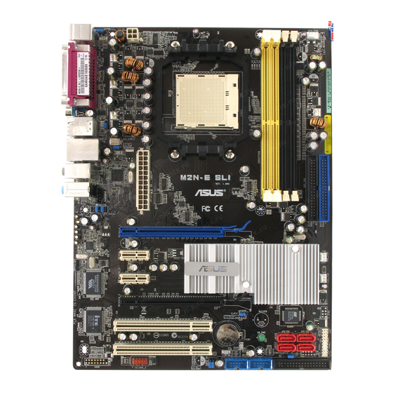
1394_USB34 USBPW34 LAN_USB12 M2N-E SLI Attansic AUDIO2 AUDIO1 FP_AUDIO PCIEX16_1 CM6501 PCIEX1_1 Nvidia NF500 SLI PCIEX1_2 PCIEX16_2 CLRTC BIOS PCI1 CR2032 3V SB_PWR SATA3 Lithium Cell SATA1 CMOS Power SATA2 SATA4 PCI2 CHASSIS USB56 USB78 FLOPPY IE1394_1 ASUS M2N-E SLI... -
Page 24: Layout Contents
2.2.4 Layout Contents Slots Page 1. DDR2 DIMM slots 2-10 2. PCI slots 2-17 3. PCI Express x16 slot 2-18 4. PCI Express x1 slot 2-18 Slots Page 1. CLRTC (3-pin CLRTC1) 2-19 2. USB device wake-up (3-pin USBPW12, USBPW34, USBPW56, USBPW78, USBPW910) 2-20 3. -
Page 25: Central Processing Unit (Cpu)
2.3.1 Installing the CPU To install a CPU: Locate the CPU socket on the motherboard. M2N-E SLI M2N-E SLI CPU Socket M2 Unlock the socket by pressing the lever sideways, then lift it up to a 90º angle. Socket lever Make sure that the socket lever is lifted up to a 90º... - Page 26 Position the CPU above the socket such that the CPU corner with the gold triangle matches the socket corner with a small triangle. Gold triangle Small triangle When the CPU is in place, push down the socket lever to secure the CPU.
-
Page 27: Installing The Heatsink And Fan
Retention bracket lock Your boxed CPU heatsink and fan assembly should come with installation instructions for the CPU, heatsink, and the retention mechanism. If the instructions in this section do not match the CPU documentation, follow the latter. ASUS M2N-E SLI... - Page 28 Attach one end of the retention bracket to the retention module base. Align the other end of the retention bracket (near the retention bracket lock) to the retention module base. A clicking sound denotes that the retention bracket is in place. Make sure that the fan and heatsink assembly perfectly fits the retention mechanism...
- Page 29 CPU_FAN. CPU_FAN M2N-E SLI M2N-E SLI CPU Fan Connector Do not forget to connect the CPU fan connector! Hardware monitoring errors can occur if you fail to plug this connector. ASUS M2N-E SLI...
-
Page 30: System Memory
240-pin footprint compared to the 184-pin DDR DIMM. DDR2 DIMMs are notched differently to prevent installation on a DDR DIMM socket. The figure illustrates the location of the DDR2 DIMM sockets: M2N-E SLI M2N-E SLI 240-pin DDR2 DIMM Sockets Channel Sockets Channel A... - Page 31 Always use identical DDR2 DIMM pairs for dual-channel model. For optimum compatibility, we recommend that you obtain memory modules from the same vendor. Visit the ASUS website (www.asus. com) for the latest Qualified Vendors List. Important notice on installing Windows XP 32-bit version ®...
- Page 32 Qualified Vendors List DDR2-800 DIMM socket DDR2 Vendor Model Component support Side(s) Size 512MB KINGSTON K4T51083QC KVR800D2N5/512 1024MB KINGSTON K4T51083QC KVR800D2N5/1G 1024MB KINGSTON Heat-Sink Package KHX6400D2LL/1G 1024MB KINGSTON Heat-Sink Package KHX6400D2LLK2/1GN 2048MB KINGSTON Heat-Sink Package KHX6400D2K2/2G 512MB Qimonda HYB18T256800AF25F HYS64T64020HU-25F-A 256MB Qimonda HYB18T512160BF-25F...
- Page 33 Heat-Sink Package BL12864AA663.16FD 1024MB crucial Heat-Sink Package BL12864AL664.16FD 1024MB Apacer E5108AE-6E-E 78.01092.420 512MB Apacer AM4B5708GQJS7E AU512E667C5KBGC 1024MB Apacer AM4B5708GQJS7E AU01GE667C5KBGC 512MB Apacer AM4B5708GQJS7E AU512E667C5KBGC 1024MB Apacer AU01GE667C5KBGC 512MB Kingmax KKEA88B4LAUG-29DX KLCC28F-A8KB5 1024MB Kingmax KKEA88B4LAUG-29DX KLCD48F-A8KB5 ASUS M2N-E SLI 2-13...
- Page 34 C - Supports three modules inserted into both the yellow and black slots as two pairs of dual-channel memory configuration. Visit the ASUS website (www.asus.com) for the latest memory Qualified Vendor List (QVL). 2-14...
-
Page 35: Installing A Dimm
DIMM. Support the DIMM lightly with your fingers when pressing the retaining clips. The DIMM DDR2 DIMM notch might get damaged when it flips out with extra force. Remove the DIMM from the socket. ASUS M2N-E SLI 2-15... -
Page 36: Expansion Slots
Expansion slots In the future, you may need to install expansion cards. The following sub-sections describe the slots and the expansion cards that they support. Make sure to unplug the power cord before adding or removing expansion cards. Failure to do so may cause you physical injury and damage motherboard components. -
Page 37: Interrupt Assignments
2.5.4 PCI slots The PCI slots support cards such as a LAN card, SCSI card, USB card, and other cards that comply with PCI specifications. Refer to the figure below for the location of the slots. ASUS M2N-E SLI 2-17... -
Page 38: Pci Express X1 Slot
2.5.5 PCI Express x1 slot This motherboard supports PCI Express x1 network cards, SCSI cards and other cards that comply with the PCI Express specifications. Refer to the figure below for the location of the slot. 2.5.6 PCI Express x16 slots This motherboard supports PCI Express x16 graphics cards that comply with the PCI Express specifications. -
Page 39: Jumpers
Normal Clear RTC (Default) M2N-E SLI Clear RTC RAM You do not need to clear the RTC when the system hangs due to overclocking. For system failure due to overclocking, use the C.P.R. (CPU Parameter Recall) feature. Shut down and reboot the system so the BIOS can automatically reset parameter settings to default values. - Page 40 USBPW12 USBPW34 M2N-E SLI USBPW5-8 M2N-E SLI USB Device Wake Up • The USB device wake-up feature requires a power supply that can provide 500mA on the +5VSB lead for each USB port; otherwise, the system would not power up.
- Page 41 [Disabled]). This feature requires an ATX power supply that can supply at least 1A on the +5VSB lead, and a corresponding setting in the BIOS (see section 2.5.5 APM Configuration). KBPWR +5VSB (Default) M2N-E SLI M2N-E SLI Keyboard Power Setting ASUS M2N-E SLI 2-21...
-
Page 42: Connectors
Connectors 2.7.1 Rear panel connectors PS/2 mouse port (green). This port is for a PS/2 mouse. Parallel port. This 25-pin port connects a parallel printer, a scanner, or other devices. IEEE 1394a port. This 6-pin IEEE 1394a port provides high-speed connectivity for audio/video devices, storage peripherals, PCs, or portable devices. - Page 43 13. Serial port (COM port). This 9-pin COM port is for pointing devices and other serial devices. 14. Coaxial S/PDIF Out port. This port connects an external audio output device via a coaxial S/PDIF cable. 15. PS/2 keyboard port (purple). This port is for a PS/2 keyboard. ASUS M2N-E SLI 2-23...
-
Page 44: Internal Connectors
FLOPPY NOTE: Orient the red markings on the floppy ribbon cable to PIN 1. M2N-E SLI Floppy Disk Drive Connector IDE connector (40-1 pin PRI_IDE, SEC_IDE) The onboard IDE connector is for the Ultra DMA 133/100/66 signal cable. There are three connectors on each Ultra DMA 133/100/66 signal cable: blue, black, and gray. -
Page 45: Serial Ata Connectors
NOTE: Orient the red markings (usually zigzag) on the ID ribbon cable to PIN 1. M2N-E SLI M2N-E SLI IDE Connectors Serial ATA connectors (7-pin SATA1, SATA2, SATA3, SATA4) These connectors are for the Serial ATA signal cables for Serial ATA 3.0 Gb/s hard disk and optical disk drives. - Page 46 These are not jumpers! DO NOT place jumper caps on the fan connectors! • The ASUS Q-Fan function is supported using the CPU Fan (CPU_FAN) and Chassis Fan (CHA_FAN) connectors only. CPU_FAN M2N-E SLI...
- Page 47 USB 2.0 specification that supports up to 480 Mbps connection speed. M2N-E SLI USB78 USB56 M2N-E SLI USB 2.0 Connectors Never connect a 1394 cable to the USB connectors. Doing so will damage the motherboard! The USB module is purchased separately. IEEE 1394a port connector (10-1 pin IE1394_1) This connector is for a IEEE 1394a port.
- Page 48 These connectors allow you to receive stereo audio input from sound sources such as a CD-ROM, TV-tuner, or MPEG card. M2N-E SLI Right Audio Channel Ground (black) Ground Left Audio Channel M2N-E SLI CPU Internal Audio Connector 2-28 Chapter 2: Hardware information...
-
Page 49: Front Panel Audio Connector
I/O module cable to this connector. FP_AUDIO M2N-E SLI M2N-E SLI Front panel audio connector Digital audio connector (4-1 pin SPDIF) This connector is for an additional Sony/Philips Digital Interface (S/ PDIF) port(s). Connect the S/PDIF Out module cable to this connector, then install the module to a slot opening at the back of the system chassis. -
Page 50: System Panel Connector
IDE_LED- PLED+ IDE_LED+ Requires an ATX power supply M2N-E SLI System Panel Connector • System power LED (2-pin PLED) This 2-pin connector is for the system power LED. Connect the chassis power LED cable to this connector. The system power LED lights up when you turn on the system power, and blinks when the system is in sleep mode. - Page 51 Q-Connector (System panel) ASUS Q-Connector allows you to easily to connect the chassis front panel cables to the motherboard. Perform these steps to install ASUS Q- Connector. Step 1 Connect the front panel cables to their respective connectors on the ASUS Q-Connector.
- Page 52 2-32 Chapter 2: Hardware information...
-
Page 53: Chapter 3: Powering Up
This chapter describes the power up sequence and ways of shutting down the system. Powering up... - Page 54 Chapter summary 3.1 Starting up for the first time ............3-1 Powering off the computer ............3-2 ASUS M2N-E SLI...
-
Page 55: Starting Up For The First Time
Check the jumper settings and connections or call your retailer for assistance. At power on, hold down the <Del> key to enter the BIOS Setup. Follow the instructions in Chapter 4. ASUS M2N-E SLI... -
Page 56: Powering Off The Computer
Powering off the computer 3.2.1 Using the OS shut down function If you are using Windows 2000: ® Click the Start button then click Shut Down... Make sure that the Shut Down option button is selected, then click the OK button to shut down the computer. The power supply should turn off after Windows shuts down. -
Page 57: Chapter 4: Bios Setup
This chapter tells how to change the system settings through the BIOS Setup menus. Detailed descriptions of the BIOS parameters are also provided. BIOS setup... - Page 58 Chapter summary Managing and updating your BIOS ........4-1 BIOS setup program ............4-11 Main menu ................4-15 Advanced menu ..............4-20 Power menu ................ 4-32 Boot menu ................4-37 Tools menu ................. 4-43 Exit menu ................4-44 ASUS M2N-E SLI...
-
Page 59: Managing And Updating Your Bios
CD when the BIOS file fails or gets corrupted.) ASUS EZ Flash 2 (Updates the BIOS in DOS using a floppy disk or the motherboard support CD.) ASUS Update (Updates the BIOS in Windows environment.) -
Page 60: Updating The Bios
AwardBIOS Flash Utility. Follow these instructions to update the BIOS using this utility. 1. Download the latest BIOS file from the ASUS web site. Rename the file to m2nesli.bin and save it to a floppy disk. Save only the updated BIOS file in the floppy disk to avoid loading the wrong BIOS file. - Page 61 Type the BIOS file name AwardBIOS Flash Utility for ASUS V1.01 in the File Name to (C) Phoenix Technologies Ltd. All Rights Reserved Program field, then press For NF-CK804-M2N-E SLI DATE: 11/18/2004 <Enter>. Flash Type - SST 49LF004A/B /3.3V File Name to Program: m2nesli.bin...
-
Page 62: Saving The Current Bios File
Make sure that the floppy disk has enough disk space to save the file. To save the current BIOS file using the AwardBIOS Flash Utility: AwardBIOS Flash Utility for ASUS V1.01 Follow steps 1 to 6 of (C) Phoenix Technologies Ltd. All Rights Reserved the previous section. -
Page 63: Asus Crashfree Bios 3 Utility
4.1.4 ASUS CrashFree BIOS 3 utility The ASUS CrashFree BIOS 3 is an auto recovery tool that allows you to restore the BIOS file when it fails or gets corrupted during the updating process. You can update a corrupted BIOS file using the motherboard support CD, floppy, or USB flash disk that contains the updated BIOS file. -
Page 64: Recovering The Bios From A Floppy Disk
Restart the system after the utility completes the updating process. The recovered BIOS may not be the latest BIOS version for this motherboard. Visit the ASUS website (www.asus.com) to download the latest BIOS file. Chapter 4: BIOS setup... -
Page 65: Asus Ez Flash 2 Utility
4.1.5 ASUS EZ Flash 2 utility The ASUS EZ Flash 2 feature allows you to update the BIOS without having to go through the long process of booting from a floppy disk and using a DOS-based utility. You can launch ASUS EZ Flash 2 by press <Alt> + <F2>... -
Page 66: Asus Update Utility
4.1.6 ASUS Update utility The ASUS Update is a utility that allows you to manage, save, and update the motherboard BIOS in Windows environment. The ASUS Update utility ® allows you to: • Save the current BIOS file • Download the latest BIOS file from the Internet •... -
Page 67: Updating The Bios Through The Internet
To update the BIOS through the Internet: Launch the ASUS Update utility from the Windows desktop by clicking ® Start > Programs > ASUS > ASUSUpdate > ASUSUpdate. The ASUS Update main window appears. Select Update BIOS from Select the ASUS FTP site... -
Page 68: Updating The Bios Through A Bios File
To update the BIOS through a BIOS file: Launch the ASUS Update utility from the Windows desktop by ® clicking Start > Programs > ASUS > ASUSUpdate > ASUSUpdate. The ASUS Update main window appears. Select Update BIOS from a file option from the drop-down menu, then click Next. -
Page 69: Bios Setup Program
The BIOS setup screens shown in this section are for reference purposes only, and may not exactly match what you see on your screen. • Visit the ASUS website (www.asus.com) to download the latest BIOS file for this motherboard. ASUS M2N-E SLI 4-11... -
Page 70: Bios Menu Screen
The BIOS setup screens shown in this chapter are for reference purposes only, and may not exactly match what you see on your screen. • Visit the ASUS website (www.asus.com) to download the latest BIOS information. 4-12 Chapter 4: BIOS setup... -
Page 71: Legend Bar
You cannot select an item that is not user-configurable. A configurable field is enclosed in brackets, and is highlighted when selected. To change the value of a field, select it then press <Enter> to display a list of options. Refer to “4.2.7 Pop-up window.” ASUS M2N-E SLI 4-13... -
Page 72: Pop-Up Window
Specifies the capacity and physical size of diskette Legacy Diskette A: Primary IDE Master [ST321122A] drive A. Primary IDE Slave [ASUS CDS520/A] Disabled ..[ ] Secondary IDE Master [None] 720K , 3.5 in..[ ] Secondary IDE Slave [None] 1.44M, 3.5 in. -
Page 73: Main Menu
4.3.2 System Date [Day, xx/xx/xxxx] Allows you to set the system date. 4.3.3 Legacy Diskette A [1.44M, 3.5 in.] Sets the type of floppy drive installed. Configuration options: [Disabled] [720K , 3.5 in.] [1.44M, 3.5 in.] ASUS M2N-E SLI 4-15... -
Page 74: Primary And Secondary Ide Master/Slave
4.3.5 Primary and Secondary IDE Master/Slave While entering Setup, the BIOS automatically detects the presence of IDE devices. There is a separate sub-menu for each IDE device. Select a device item then press <Enter> to display the IDE device information. Phoenix-Award BIOS CMOS Setup Utility Main Primary IDE Master... -
Page 75: Pio Mode
FDISK, to partition and format new IDE hard disk drives. This is necessary so that you can write or read data from the hard disk. Make sure to set the partition of the Primary IDE hard disk drives to active. ASUS M2N-E SLI 4-17... -
Page 76: Sata 1, 2, 3, 4
4.3.6 SATA 1, 2, 3, 4 While entering Setup, the BIOS automatically detects the presence of Serial ATA devices. There is a separate sub-menu for each SATA device. Select a device item then press <Enter> to display the SATA device information. Phoenix-Award BIOS CMOS Setup Utility Main SATA 1... -
Page 77: Hdd Smart Monitoring
Make sure to set the partition of the Primary IDE hard disk drives to active. 4.3.7 HDD SMART Monitoring [Disabled] Allows you to enable or disable the HDD Self-Monitoring Analysis and Reporting Technology (SMART) feature. Configuration options: [Disabled] [Enabled] 4.3.8 Installed Memory Shows the size of installed memory. ASUS M2N-E SLI 4-19... -
Page 78: Advanced Menu
Advanced menu The Advanced menu items allow you to change the settings for the CPU and other system devices. Take caution when changing the settings of the Advanced menu items. Incorrect field values can cause the system to malfunction. Phoenix-Award BIOS CMOS Setup Utility Main Advanced Power... - Page 79 Sets the operating DDR voltage. Configuration options: [Auto] [1.80V] [1.85V] [1.90V] [1.95V] CPU Multiplier [Auto] Sets the operating CPU multiplier. The configuration options vary depending on the type of CPU installed. Configuration options: [Auto] [5x] [6x] [7x] [8x] [9x] ASUS M2N-E SLI 4-21...
- Page 80 CPU Voltage [Auto] Sets the operating CPU voltage. The configuration options vary depending on the model of processor installed. PCI Clock Synchronization Mode [Auto] Sets the PCI Clock Synchronization mode. Configuration options: [Auto] [To CPU] [33.33MHz] 4-22 Chapter 4: BIOS setup...
-
Page 81: Cpu Configuration
-/+: Change Value F5: Setup Defaults →←: Select Menu ESC: Exit Enter: Select Sub-menu F10: Save and Exit Memory Clock Frequency[Auto] Sets platform Memclock or limit value. Configuration options: [Auto] [DDR2 400] [DDR2 533] [DDR2 667] [DDR2 800] ASUS M2N-E SLI 4-23... - Page 82 DRAM Timing Control Load Fail-Safe Defaults Configuration options: [YES] [NO] USB Keyboard Support [Enabled] Configuration options: [Disabled] [Enabled] USB Mouse Support [Enabled] Configuration options: [Disabled] [Enabled] Onboard FDC Controller [Enabled] Configuration options: [Disabled] [Enabled] CKE Fine Delay [Auto] Configuration options: [Auto] [No delay] [1/64 MEMCLK delay] [2/64 MEMCLK delay] [3/64 MEMCLK delay] [4/64 MEMCLK delay] [5/64 MEMCLK delay]...[30/64 MEMCLK delay] [31/64 MEMCLK delay] CKE Setup Time [Auto]...
- Page 83 Twtr[Auto] Configuration options: [Auto] [1] [2] [3] Trtp[Auto] Configuration options: [Auto] [2/4] [3/5] Twrrd[Auto] Configuration options: [Auto] [0] [1] [2] [3] Twrwr[Auto] Configuration options: [Auto] [1] [2] [3] Trdrd[Auto] Configuration options: [Auto] [2] [3] [4] [5] ASUS M2N-E SLI 4-25...
-
Page 84: Pcipnp
Trfc[Auto] Configuration options: [Auto] [0] [1] [2] [3] 1T/2T Memory Timing[Auto] Configuration Options: [Auto] [1T] [2T] Hyper Transport Frequency [Auto] Configuration options: [1x] [2x] [3x] [4x] [5x] [Auto] AMD Live! [Disabled] Enables or disables AMD Live! technology. Configuration options: [Disabled] [Enabled] AMD Cool’n’Quiet Function [Disabled] Enables or disables the AMD Cool’n’Quiet function. -
Page 85: Onboard Device Configuration
Configuration options: [Disabled] [Enabled] OnChip IDE Channel1[Enabled] Allows to disable or enable OnChip IDE Channel1 Configuration options: [Disabled] [Enabled] IDE DMA transfer access[Enabled] Allows to disable or enable IDE DMA transfer access Configuration options: [Disabled] [Enabled] ASUS M2N-E SLI 4-27... - Page 86 SATA Port 1, 2[Enabled] Allows to disable or enable OnChip SATA(Port 1, Port 2) Configuration options: [Disabled] [Enabled] SATA DMA transfer [Enabled] Allows to disable or enable to switch to support SATA DMA tranfer Configuration options: [Disabled] [Enabled] SATA Port 3, 4[Enabled] Allows to disable or enable OnChip SATA2(Port 3, Port 4) Configuration options: [Disabled] [Enabled] SATA2 DMA transfer [Enabled]...
-
Page 87: Nvraid Configuration
Selects this device as RAID set. Configuration options: [Disabled] [Enabled] SATA 3 RAID[Disabled] Selects this device as RAID set. Configuration options: [Disabled] [Enabled] SATA 4 RAID[Disabled] Selects this device as RAID set. Configuration options: [Disabled] [Enabled] ASUS M2N-E SLI 4-29... -
Page 88: Usb Configuration
USB Configuration The items in this sub-menu allows you to set the USB configuration. Phoenix-Award BIOS CMOS Setup Utility Advanced USB Configuration Select Menu USB Controller [Enabled] Item Specific Help USB 2.0 Controller [Enabled] USB Legacy support [Enabled] Press [Enter] to set. ↑↓... - Page 89 Configuration options: [Disabled] [378/IRQ7] [278/IRQ5] [3BC/IRQ7] Parallel Port Mode [EPP] Allows you to select the Parallel Port mode. Configuration options: [Normal] [EPP] [ECP] [Bi-Directional] ECP Mode Use DMA [3] Allows selection of ECP Mode. Configuration options: [1] [3] ASUS M2N-E SLI 4-31...
-
Page 90: Sli Configuration
4.4.6 SLI Configuration Phoenix-Award BIOS CMOS Setup Utility Advanced SLI Configuration Select Menu AI-Selector [Auto] Item Specific Help ↑↓ : Select Item F1:Help -/+: Change Value F5: Setup Defaults →←: Select Menu ESC: Exit Enter: Select Sub-menu F10: Save and Exit AI-Selector[Auto] Allows selection of the Scalable Link Interface mode. -
Page 91: Power Menu
Allows you to enable or disable the Advanced Configuration and Power Interface (ACPI) support in the Application-Specific Integrated Circuit (ASIC). When set to Enabled, the ACPI APIC table pointer is included in the RSDT pointer list. Configuration options: [Disabled] [Enabled] ASUS M2N-E SLI 4-33... -
Page 92: Apm Configuration
4.5.3 APM Configuration Phoenix-Award BIOS CMOS Setup Utility Power Select Menu APM Configuration Restore on AC Power Loss [Power-Off] Item Specific Help PWR Button < 4 secs [Instant-Off] Power On By PCI/PCIE Devices [Disabled] Press [ENTER] to Power On By External Modems [Disabled] select whether or not Power On By RTC Alarm... - Page 93 Allows you to disable the Power On by PS/2 keyboard function or set specific keys on the PS/2 keyboard to turn on the system. This feature requires an ATX power supply that provides at least 1A on the +5VSB lead. Configuration options: [Disabled] [Space Bar] [Ctrl-ESC] [Power Key] ASUS M2N-E SLI 4-35...
-
Page 94: Hardware Monitor
4.5.4 Hardware Monitor The items in this sub-menu displays the hardware monitor values automatically detected by the BIOS. It also allows you to change CPU Q-Fan feature-related parameters. Select an item then press <Enter> to display the configuration options. Phoenix-Award BIOS CMOS Setup Utility Power Hardware Monitor Select Menu... - Page 95 Configuration options: [Disabled] [800 RPM] [1200 RPM] [1600 RPM] Please be careful when the CPU Fan speed warning is set to [Disabled]. It will not produce and warning message during POST even the fan is bad or not present. ASUS M2N-E SLI 4-37...
-
Page 96: Boot Menu
Boot menu The Boot menu items allow you to change the system boot options. Select an item then press <Enter> to display the sub-menu. Phoenix-Award BIOS CMOS Setup Utility Main Advanced Power Boot Exit Boot Device Priority Select Menu Removable Drives Item Specific Help Boot Settings Configuration Security... -
Page 97: Removable Drives
Enter: Select Sub-menu F10: Save and Exit 1. Floppy Disks Allows you to assign a removable drive attached to the system. 2. Netac OnlyDisk 2010 Allows you to assign a removable drive attached to the system. ASUS M2N-E SLI 4-39... -
Page 98: Boot Settings Configuration
4.6.3 Boot Settings Configuration Phoenix-Award BIOS CMOS Setup Utility Boot Boot Settings Configuration Select Menu Case Open Warning [Enabled] Item Specific Help Quick Boot [Enabled] Boot Up Floppy Seek [Disabled] Press [Enter] to Bootup Num-Lock [On] enable or disable. Typematic Rate Setting [Disabled] Typematic Rate (Chars/Sec) Typematic Delay (Msec) - Page 99 Make sure that the above item is set to [Enabled] if you want to use the ASUS MyLogo2™ feature. • See section “5.4.1 ASUS MyLogo2™” for details. Halt On [All, But Keyboard] Allows you to error report type. Configuration options: [All Errors] [No Errors] [All, But Keyboard]...
-
Page 100: Security
4.6.4 Security Phoenix-Award BIOS CMOS Setup Utility Boot Security Select Menu Supervisor Password Clear Item Specific Help User Password Clear Password Check [Setup] Supervisor password controls full access, <Enter> to change password. ↑↓ : Select Item F1:Help -/+: Change Value F5: Setup Defaults →←: Select Menu ESC: Exit... -
Page 101: Password Check
This field requires you to enter the password before entering the BIOS setup or the system. Select [Setup] to require the password before entering the BIOS Setup. Select [System] to require the password before entering the system. Configuration options: [Setup] [System] ASUS M2N-E SLI 4-43... -
Page 102: Tools Menu
Item Specific Help ASUS EZ Flash 2 Allows you to run ASUS EZ Flash 2. Press <Enter> to start EZ Flash 2 then from the confirmation screen, use the left or right arrows to select [Yes] or [No] then press <Enter>. See page 4-5 for details. -
Page 103: Exit Menu
Select this option only if you do not want to save the changes that you made to the Setup program. If you made changes to fields other than System Date, System Time, and Password, the BIOS asks for a confirmation before exiting. ASUS M2N-E SLI 4-45... -
Page 104: Load Setup Defaults
Load Setup Defaults This option allows you to load the default values for each of the parameters on the Setup menus. When you select this option or if you press <F5>, a confirmation window appears. Select Yes to load default values. -
Page 105: Chapter 5: Software Support
This chapter describes the contents of the support CD that comes with the motherboard package. Software support... - Page 106 Chapter summary Installing an operating system ..........5-1 Support CD information ............5-1 Software information ............5-8 RAID configurations ............5-16 Creating a RAID driver disk ..........5-25 ASUS M2N-E SLI...
-
Page 107: Installing An Operating System
The contents of the support CD are subject to change at any time without notice. Visit the ASUS website(www.asus.com) for updates. 5.2.1 Running the support CD Place the support CD to the optical drive. -
Page 108: Drivers Menu
5.2.2 Drivers menu The drivers menu shows the available device drivers if the system detects installed devices. Install the necessary drivers to activate the devices. NVIDIA nForce Chipset Driver Installs the NVIDIA Chipset drivers for the NVIDIA nForce 500 SLI ®... -
Page 109: Utilities Menu
This utility helps you keep your computer in healthy operating condition. ASUS Update Allows you to download the latest version of the BIOS from the ASUS website. Before using the ASUS Update, make sure that you have an Internet connection so you can connect to the ASUS website. -
Page 110: Make Disk Menu
Microsoft DirectX 9.0c Installs the Microsoft DirectX 9.0 driver. The Microsoft DirectX 9.0 is ® ® a multimedia technology that enhances computer graphics and sound. DirectX improves the multimedia features of you computer so you can ® enjoy watching TV and movies, capturing videos, or playing games in your computer. -
Page 111: Manuals Menu
® ® opening a user manual file. • Some user manuals listed in this menu may not be applicable for this motherboard model. NVIDIA RAID User’s Guide Allows you to open the NVIDIA RAID User’s Guide. ® ASUS M2N-E SLI... -
Page 112: Asus Contact Information
5.2.6 ASUS Contact information Click the Contact tab to display the ASUS contact information. You can also find this information on the inside front cover of this user guide. 5.2.7 Other information The icons on the top right corner of the screen give additional information on the motherboard and the contents of the support CD. -
Page 113: Browse This Cd
Browse this CD Displays the support CD contents in graphical format. Technical support Form Displays the ASUS Technical Support Request Form that you have to fill out when requesting technical support. ASUS M2N-E SLI... - Page 114 Filelist Displays the contents of the support CD and a brief description of each in text format. Chapter 5: Software support...
-
Page 115: Software Information
Click the Power... button. The following dialog box appears. From the Power schemes combo list box, select Minimal Power Management. Click OK to effect settings. Make sure to install the Cool ‘n’ Quiet!™ driver and application before using this feature. ASUS M2N-E SLI... -
Page 116: Launching The Cool 'N' Quiet!™ Software
AMD heatsink and fan assembly with monitor chip • If you purchased a separate heatsink and fan package, use the ASUS Q-Fan technology feature to automatically adjust the CPU fan speed according to your system loading. Launching the Cool ‘n’ Quiet!™ software The motherboard support CD includes the Cool ‘n’... -
Page 117: Asus Pc Probe Ii
To launch the PC Probe II from the Windows desktop, click Start > All ® Programs > ASUS > PC Probe II > PC Probe II v1.00.43. The PC Probe II main window appears. After launching the application, the PC Probe II icon appears in the Windows taskbar. - Page 118 Button Function Opens the Configuration window Opens the Report window Opens the Desktop Management Interface window Opens the Peripheral Component Interconnect window Opens the Windows Management Instrumentation window Opens the hard disk drive, memory, CPU usage window Shows/Hides the Preference section Minimizes the application Closes the application Sensor alert...
- Page 119 You can also adjust value the threshold values using the Config Click to window. decrease value You cannot adjust the sensor threshold values in a small monitoring panel. ASUS M2N-E SLI 5-13...
- Page 120 Monitoring sensor alert The monitor panel turns red when a component value exceeds or is lower than the threshold value. Refer to the illustrations below. Small display Large display WMI browser Click to display the WMI (Windows Management Instrumentation) browser. This browser displays various Windows ®...
- Page 121 The left panel of the tab lists all logical drives. Click a hard disk drive to display the information on the right panel. The pie chart at the bottom of the window represents the used (blue) and the available HDD space. ASUS M2N-E SLI 5-15...
- Page 122 Memory usage The Memory tab shows both used and available physical memory. The pie chart at the bottom of the window represents the used (blue) and the available physical memory. Configuring PC Probe II Click to view and adjust the sensor threshold values. The Config window has two tabs: Sensor/Threshold and Preference.
-
Page 123: Raid Configurations
Spanning does not deliver any advantage over using separate disks independently and does not provide fault tolerance or other RAID performance benefits. ASUS M2N-E SLI 5-17... -
Page 124: Installing Hard Disks
If you want to boot the system from a hard disk drive included in a RAID set, copy first the RAID driver from the support CD to a floppy disk before you install an operating system to a selected hard disk drive. Refer to section “5.6 Creating a RAID driver disk”... -
Page 125: Nvidia ® Raid Configurations
RAID. See section “5.4.3 Onboard Devices Configuration” for details. Save your changes and Exit Setup. For detailed descriptions on the NVIDIA® RAID configuration, refer to the “NVIDIA RAID User’s Manual” found in your motherboard support CD. ® ASUS M2N-E SLI 5-19... -
Page 126: Creating A Raid Volume
Entering the NVIDIA RAID utility ® To enter the NVIDIA RAID utility: ® Boot up your computer. During POST, press <F10> to display the main menu of the utility. The RAID BIOS setup screens shown in this section are for reference only, and may not exactly match the items on your screen. - Page 127 [N] NO Press <Y> to clear the selected disks or <N> to proceed without clearing the disks. The following screen appears. Take caution in using this option. All data on the RAID drives will be lost! ASUS M2N-E SLI 5-21...
-
Page 128: Rebuilding A Raid Array
NVIDIA RAID Utility Oct 5 2004 - Array List - Boot Status Vendor Array Model Name Healthy NVIDIA MIRROR XXX.XXG [Ctrl-X]Exit [↑↓]Select [B]Set Boot [N]New Array [ENTER]Detail A new set of navigation keys is displayed on the bottom of the screen. - Page 129 Use the up or down arrow keys to select a RAID array to rebuild, then press <F7>. The following confirmation message appears. Rebuild array? [ENTER] OK [ESC] Cancel Press <Enter> to start rebuilding array or press <Esc> to cancel. After the rebuild process, the Array list menu appears. ASUS M2N-E SLI 5-23...
-
Page 130: Deleting A Raid Array
Deleting a RAID array To delete a RAID array: From the Array List menu, use the up or down arrow keys to select a RAID array then press <Enter>. The RAID Array details appear. Array 1 : NVIDIA MIRROR XXX.XXG - Array Detail - RAID Mode: Mirroring Striping Width: 1... -
Page 131: Clearing A Disk Data
Press <C> to clear disk. The following confirmation message appears. Clear disk data? [Y] YES Press <Y> to clear the disk data or press <N> to cancel. Take caution in using this option. All data on the RAID drives will be lost! ASUS M2N-E SLI 5-25... -
Page 132: Creating A Raid Driver Disk
Creating a RAID driver disk A floppy disk with the RAID driver is required when installing Windows ® 2000/XP operating system on a hard disk drive that is included in a RAID set. To create a RAID driver disk: Place the motherboard support CD into the CD-ROM drive. When the Drivers menu appears, select the RAID driver disk you want to create: •... -
Page 133: Nvidia Sli
This chapter tells how to install SLI-ready PCI Express graphics cards. ® NVIDIA SLI™ technology support... - Page 134 Chapter summary Overview ..................6-1 Dual graphics cards setup ............6-2 ASUS M2N-E SLI...
-
Page 135: Overview
See “9. ATX power connectors” on page 2-28 for details. • The NVIDIA SLI technology supports Windows XP™ 32-bit/64bit operating ® system only. • Visit the NVIDIA zone website (http://www.nzone.com) for the latest certified graphics card and supported 3D application list. ASUS M2N-E SLI... -
Page 136: Dual Graphics Card Setup
Dual graphics card setup 6.2.1 Installing SLI-ready graphics cards Install only identical SLI-ready graphics cards that are NVIDIA -certified. ® Different types of graphics cards will not work together properly. To install the graphics cards: Prepare two graphics cards. Each graphics card should have goldfingers for the SLI connector. - Page 137 Insert the second graphics card into the other slot. Make sure that the card is properly seated on the slot. If required, connect an auxiliary power source to the PCI Express graphics cards. ASUS M2N-E SLI...
- Page 138 Align and insert the SLI connector to the goldfingers on each graphics card. Make sure that the connector is firmly in place. SLI connector When installing two VGA cards using a 20-pin ATX PSU with sufficient+12v capability, we recommend that you connect the auxillary power source from the power supply to the graphics card. Refer to the PSU documentation for dual VGA power requirements.
-
Page 139: Installing The Device Drivers
Windows taskbar. NVIDIA Settings icon From the pop-up menu, select nView Desktop Manager then click nView Properties. From the nView Desktop Manager window, select the Desktop Management tab. Click Properties to display the Display Properties dialog box. ASUS M2N-E SLI... - Page 140 From the Display Properties dialog box, select the Settings tab then click Advanced. Select the NVIDIA GeForce tab. Click the slider to display the following screen, then select the SLI multi-GPU item. Slider Click the Enable SLI multi-GPU check box. Click OK when done.