Table of Contents
Advertisement
Advertisement
Table of Contents

Related Manuals for Asus Motherboard M2NPV-MX


Summary of Contents for Asus Motherboard M2NPV-MX
- Page 1 M2NPV-MX...
- Page 2 Product warranty or service will not be extended if: (1) the product is repaired, modified or altered, unless such repair, modification of alteration is authorized in writing by ASUS; or (2) the serial number of the product is defaced or missing.
-
Page 3: Table Of Contents
Welcome! ... 1-2 Package contents ... 1-2 Special features ... 1-2 1.3.1 Product highlights ... 1-2 1.3.2 Innovative ASUS features ... 1-5 Before you proceed ... 1-6 Motherboard overview ... 1-7 1.5.1 Motherboard layout ... 1-7 1.5.2 Placement direction ... 1-8 1.5.3... - Page 4 Managing and updating your BIOS ... 2-2 2.1.1 ASUS Update utility ... 2-2 2.1.2 Creating a bootable floppy disk ... 2-5 2.1.3 ASUS EZ Flash 2 utility ... 2-6 2.1.4 Updating the BIOS ... 2-7 2.1.5 Saving the current BIOS file ... 2-9 2.1.6 ASUS CrashFree BIOS 2 utility ...
- Page 5 Boot Settings Configuration ... 2-35 2.6.6 Security ... 2-38 Tools menu ... 2-40 2.7.1 ASUS EZ Flash 2 ... 2-40 Exit menu ... 2-41 Chapter 3: Software support Chapter 3: Software support Chapter 3: Software support Chapter 3: Software support Chapter 3: Software support Installing an operating system ...
-
Page 6: Notices
Notices Federal Communications Commission Statement Federal Communications Commission Statement Federal Communications Commission Statement Federal Communications Commission Statement Federal Communications Commission Statement This device complies with Part 15 of the FCC Rules. Operation is subject to the following two conditions: • This device may not cause harmful interference, and •... -
Page 7: Safety Information
Safety information Electrical safety Electrical safety Electrical safety Electrical safety Electrical safety • To prevent electrical shock hazard, disconnect the power cable from the electrical outlet before relocating the system. • When adding or removing devices to or from the system, ensure that the power cables for the devices are unplugged before the signal cables are connected. -
Page 8: M2Npv-Mx Specifications Summary
M2NPV-MX specifications summary C P U C P U C P U C P U C P U Support AMD socket AM2 for AMD Athlon™ 64FX/ Athlon™ 64 X2/Athlon™ 64/Sempron processors AMD64 architecture enables simultaneous 32-bit and 64-bit computing Supports AMD Cool ‘n’ Quiet™ Technology AMD Live!™... - Page 9 Stepless Frequency Selection (SFS) allows FSB tuning from 200 MHz to 400 MHz at 1 MHz increment N o t e : ASUS CrashFree BIOS 2 and ASUS EZ Flash 2 only N o t e : N o t e :...
- Page 10 ASUS PC Probe II AMD Cool ‘n’Quiet™ utility ASUS Live Update utility Anti-virus software (OEM version) *Specifications are subject to change without notice.
- Page 11 This chapter describes the motherboard features and the new technologies it supports. Product introduction...
-
Page 12: Welcome
T h a n k y o u f o r b u y i n g a n A S U S The motherboard delivers a host of new features and latest technologies, making it another standout in the long line of ASUS quality motherboards! Before you start installing the motherboard, and hardware devices on it, check the items in your package with the list below. - Page 13 AMD Cool ‘n’ Quiet Technology AMD Cool ‘n’ Quiet Technology AMD Cool ‘n’ Quiet Technology AMD Cool ‘n’ Quiet Technology AMD Cool ‘n’ Quiet Technology The motherboard supports the AMD Cool ‘n’ Quiet Technology, which monitors system operation and automatically adjusts CPU voltage and frequency for a cool and quiet operating environment.
- Page 14 Serial ATA 3Gb/s technology Serial ATA 3Gb/s technology Serial ATA 3Gb/s technology Serial ATA 3Gb/s technology Serial ATA 3Gb/s technology The motherboard supports next-generation SATA hard drives based on the new SATA 3Gb/s storage specification. The onboard NVIDIA MCP southbridge allows RAID 0, RAID 1, RAID 0+1, RAID 5, and JBOD configurations for four SATA connectors.
-
Page 15: Innovative Asus Features
ASUS EZ Flash 2 ASUS EZ Flash 2 With the ASUS EZ Flash, you can easily update the system BIOS even before loading the operating system. No need to use a DOS-based utility or boot from a floppy disk. See page 2-6 for details. -
Page 16: Before You Proceed
Before you proceed Take note of the following precautions before you install motherboard components or change any motherboard settings. • Unplug the power cord from the wall socket before touching any component. • Use a grounded wrist strap or touch a safely grounded object or a metal object, such as the power supply case, before handling components to avoid damaging them due to static electricity •... -
Page 17: Motherboard Overview
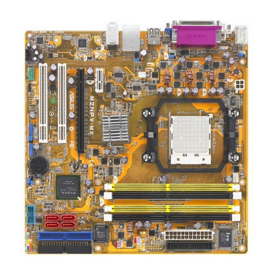
Motherboard overview 1.5.1 1.5.1 Motherboard layout Motherboard layout 1.5.1 1.5.1 1.5.1 Motherboard layout Motherboard layout Motherboard layout 24.5cm (9.6in) PS/2KBMS T: Mouse KBPWR B: Keyboard ATX12V USBPW12 USB12 CHA_FAN1 LAN_USB34 USBPW34 nVIDIA Top:Line In Center:Line Out GeForce™6150 Bottom:Mic In TV_OUT PCIEX1_1 M2NPV-MX 88E1116... -
Page 18: Placement Direction
1.5.2 1.5.2 1.5.2 Placement direction Placement direction Placement direction 1.5.2 1.5.2 Placement direction Placement direction When installing the motherboard, make sure that you place it into the chassis in the correct orientation. The edge with external ports goes to the rear part of the chassis as indicated in the image below. -
Page 19: Central Processing Unit (Cpu)
Central Processing Unit (CPU) The motherboard comes with a 940-pin AM2 socket designed for the AMD Athlon™ 64 X2/Athlon™ 64/Athlon™ FX/Sempron™ processor. The AM2 socket has a different pinout from the 940-pin socket designed for the AMD Opteron™ processor. Make sure you use a CPU is designed for the AM2 socket. - Page 20 Position the CPU above the socket such that the CPU corner with the gold triangle matches the socket corner with a small triangle. Carefully insert the CPU into the socket until it fits in place. The CPU fits only in one correct orientation. DO NOT force the CPU into the socket to prevent bending the pins and damaging the CPU! When the CPU is in place, push down the socket lever to secure...
-
Page 21: Installing The Heatsink And Fan
1.6.2 1.6.2 1.6.2 1.6.2 1.6.2 Installing the heatsink and fan Installing the heatsink and fan Installing the heatsink and fan Installing the heatsink and fan Installing the heatsink and fan The AMD Athlon™ 64/Sempron™ processor require a specially designed heatsink and fan assembly to ensure optimum thermal condition and performance. - Page 22 Attach one end of the retention bracket to the retention module base. Align the other end of the retention bracket (near the retention bracket lock) to the retention module base. A clicking sound denotes that the retention bracket is in place. Make sure that the fan and heatsink assembly perfectly fits the retention mechanism...
-
Page 23: System Memory
System memory 1.7.1 1.7.1 1.7.1 Overview Overview Overview 1.7.1 1.7.1 Overview Overview The motherboard comes with four Double Data Rate 2 (DDR2) Dual Inline Memory Modules (DIMM) sockets. A DDR2 module has the same physical dimensions as a DDR DIMM but has a 240-pin footprint compared to the 184-pin DDR DIMM. - Page 24 DIMM_B2 (black sockets) Always use identical DDR2 DIMM pairs for dual-channel model. For optimum compatibility, we recommend that you obtain memory modules from the same vendor. Visit the ASUS website (www.asus.com) for the latest Qualified Vendors List. Important notice on installing Windows...
- Page 25 Qualified Vendors Lists (QVL) Qualified Vendors Lists (QVL) Qualified Vendors Lists (QVL) Qualified Vendors Lists (QVL) Qualified Vendors Lists (QVL) DDR2-800 MHz capability S i z e S i z e S i z e S i z e S i z e V e n d o r V e n d o r V e n d o r...
- Page 26 C C C C C Supports 3 modules inserted into both the blue and black slots as two pairs of Dual-channel memory configuration. Visit the ASUS website for the latest DDR2-800/667/533 MHz QVL. 1 - 1 6 1 - 1 6...
-
Page 27: Installing A Dimm
1.7.3 1.7.3 1.7.3 1.7.3 1.7.3 Installing a DIMM Installing a DIMM Installing a DIMM Installing a DIMM Installing a DIMM Make sure to unplug the power supply before adding or removing DIMMs or other system components. Failure to do so may cause severe damage to both the motherboard and the components. -
Page 28: Expansion Slots
Expansion slots In the future, you may need to install expansion cards. The following sub-sections describe the slots and the expansion cards that they support. Make sure to unplug the power cord before adding or removing expansion cards. Failure to do so may cause you physical injury and damage motherboard components. - Page 29 Standard interrupt assignments Standard interrupt assignments Standard interrupt assignments Standard interrupt assignments Standard interrupt assignments I R Q I R Q I R Q I R Q I R Q P r i o r i t y P r i o r i t y P r i o r i t y P r i o r i t y P r i o r i t y...
-
Page 30: Pci Slots
1.8.3 1.8.3 1.8.3 1.8.3 1.8.3 PCI slots PCI slots PCI slots PCI slots PCI slots The PCI slots support cards such as a LAN card, SCSI card, USB card, and other cards that comply with PCI specifications. The figure shows a LAN card installed on a PCI slot. -
Page 31: Jumpers
Jumpers 1 . 1 . C l e a r R T C R A M ( C L R T C ) C l e a r R T C R A M ( C L R T C ) C l e a r R T C R A M ( C L R T C ) C l e a r R T C R A M ( C L R T C ) C l e a r R T C R A M ( C L R T C ) - Page 32 2 . 2 . U S B d e v i c e w a k e - u p ( 3 - p i n U S B P W 1 2 , U S B P W 3 4 , U S B d e v i c e w a k e - u p ( 3 - p i n U S B P W 1 2 , U S B P W 3 4 , U S B d e v i c e w a k e - u p ( 3 - p i n U S B P W 1 2 , U S B P W 3 4 , U S B d e v i c e w a k e - u p ( 3 - p i n U S B P W 1 2 , U S B P W 3 4 ,...
- Page 33 3 . 3 . K e y b o a r d p o w e r ( 3 - p i n K B P W R ) K e y b o a r d p o w e r ( 3 - p i n K B P W R ) K e y b o a r d p o w e r ( 3 - p i n K B P W R ) K e y b o a r d p o w e r ( 3 - p i n K B P W R ) K e y b o a r d p o w e r ( 3 - p i n K B P W R )
-
Page 34: 1.10 Connectors
1.10 Connectors 1.10.1 1.10.1 1.10.1 Rear panel connectors Rear panel connectors Rear panel connectors Rear panel connectors 1.10.1 1.10.1 Rear panel connectors 1 . 1 . P S / 2 m o u s e p o r t ( g r e e n ) . P S / 2 m o u s e p o r t ( g r e e n ) . - Page 35 Audio 2, 4, or 6-channel configuration Audio 2, 4, or 6-channel configuration Audio 2, 4, or 6-channel configuration Audio 2, 4, or 6-channel configuration Audio 2, 4, or 6-channel configuration P o r t P o r t H e a d s e t H e a d s e t P o r t P o r t...
-
Page 36: Internal Connectors
1.10.2 Internal connectors 1.10.2 1.10.2 1.10.2 1.10.2 Internal connectors Internal connectors Internal connectors Internal connectors 1 . 1 . F l o p p y d i s k d r i v e c o n n e c t o r ( 3 4 - 1 p i n F L O P P Y ) F l o p p y d i s k d r i v e c o n n e c t o r ( 3 4 - 1 p i n F L O P P Y ) F l o p p y d i s k d r i v e c o n n e c t o r ( 3 4 - 1 p i n F L O P P Y ) F l o p p y d i s k d r i v e c o n n e c t o r ( 3 4 - 1 p i n F L O P P Y ) - Page 37 3 . 3 . I D E c o n n e c t o r s ( 4 0 - 1 p i n P R I _ I D E ; 4 0 - 1 p i n S E C _ I D E ) I D E c o n n e c t o r s ( 4 0 - 1 p i n P R I _ I D E ;...
- Page 38 4 . 4 . S e r i a l A T A c o n n e c t o r s S e r i a l A T A c o n n e c t o r s S e r i a l A T A c o n n e c t o r s S e r i a l A T A c o n n e c t o r s S e r i a l A T A c o n n e c t o r s...
- Page 39 5 . 5 . C P U , C h a s s i s , a n d P o w e r F a n c o n n e c t o r s C P U , C h a s s i s , a n d P o w e r F a n c o n n e c t o r s C P U , C h a s s i s , a n d P o w e r F a n c o n n e c t o r s C P U , C h a s s i s , a n d P o w e r F a n c o n n e c t o r s C P U , C h a s s i s , a n d P o w e r F a n c o n n e c t o r s...
- Page 40 7 . 7 . U S B c o n n e c t o r s ( 1 0 - 1 p i n U S B 5 6 , U S B 7 8 ) U S B c o n n e c t o r s ( 1 0 - 1 p i n U S B 5 6 , U S B 7 8 ) U S B c o n n e c t o r s ( 1 0 - 1 p i n U S B 5 6 , U S B 7 8 ) U S B c o n n e c t o r s ( 1 0 - 1 p i n U S B 5 6 , U S B 7 8 ) U S B c o n n e c t o r s ( 1 0 - 1 p i n U S B 5 6 , U S B 7 8 )
- Page 41 9 . 9 . T V - o u t c o n n e c t o r ( 8 - 1 p i n T V _ O U T ) T V - o u t c o n n e c t o r ( 8 - 1 p i n T V _ O U T ) T V - o u t c o n n e c t o r ( 8 - 1 p i n T V _ O U T ) T V - o u t c o n n e c t o r ( 8 - 1 p i n T V _ O U T ) T V - o u t c o n n e c t o r ( 8 - 1 p i n T V _ O U T )
- Page 42 1 0 . 1 0 . S e r i a l p o r t c o n n e c t o r ( 1 0 - 1 p i n C O M 1 ) 1 0 . S e r i a l p o r t c o n n e c t o r ( 1 0 - 1 p i n C O M 1 ) S e r i a l p o r t c o n n e c t o r ( 1 0 - 1 p i n C O M 1 ) S e r i a l p o r t c o n n e c t o r ( 1 0 - 1 p i n C O M 1 )
-
Page 43: Atx Power Connectors
1 2 . 1 2 . 1 2 . A T X p o w e r c o n n e c t o r s ( 2 4 - p i n E A T X P W R , 4 - p i n A T X 1 2 V ) 1 2 . -
Page 44: System Panel Connector
1 3 . S y s t e m p a n e l c o n n e c t o r ( 2 0 - 1 p i n P A N E L ) 1 3 . 1 3 . - Page 45 This chapter tells how to change the system settings through the BIOS Setup menus. Detailed descriptions of the BIOS parameters are also provided. BIOS setup...
-
Page 46: Managing And Updating Your Bios
ASUS Update utility 2.1.1 2.1.1 ASUS Update utility ASUS Update utility The ASUS Update is a utility that allows you to manage, save, and update the motherboard BIOS in Windows allows you to: • Save the current BIOS file •... - Page 47 Updating the BIOS through the Internet To update the BIOS through the Internet: Launch the ASUS Update utility from the Windows S t a r t > P r o g r a m s S t a r t...
- Page 48 S t a r t P r o g r a m s A S U S U p d a t e. The ASUS Update main window appears. A S U S U p d a t e A S U S U p d a t e...
-
Page 49: Creating A Bootable Floppy Disk
2.1.2 2.1.2 2.1.2 2.1.2 2.1.2 Creating a bootable floppy disk Creating a bootable floppy disk Creating a bootable floppy disk Creating a bootable floppy disk Creating a bootable floppy disk Do either one of the following to create a bootable floppy disk. DOS environment a. -
Page 50: Asus Ez Flash 2 Utility
ASUS EZ Flash 2 utility ASUS EZ Flash 2 utility The ASUS EZ Flash 2 feature allows you to update the BIOS without having to go through the long process of booting from a floppy disk and using a DOS-based utility. The EZ Flash utility is built-in the BIOS chip so it is accessible by pressing <Alt>... -
Page 51: Updating The Bios
AwardBIOS Flash Utility. Follow these instructions to update the BIOS using this utility. 1. Download the latest BIOS file from the ASUS web site. Rename the file to M 2 N P V M X . b i n M 2 N P V M X . b i n M 2 N P V M X . - Page 52 2 - 8 2 - 8 2 - 8 2 - 8 2 - 8 AwardBIOS Flash Utility for ASUS V1.17 (C) Phoenix Technologies Ltd. All Rights Reserved For C51PV-MCP51-M2NPV-MX-00 DATE: 04/13/2006 Flash Type - PMC Pm49FL004T LPC/FWH File Name to Program: 0107.bin...
-
Page 53: Saving The Current Bios File
A S U S M 2 N P V - M X A S U S M 2 N P V - M X A S U S M 2 N P V - M X AwardBIOS Flash Utility for ASUS V1.17 DATE: 04/13/2006 0107.bin Please wait... -
Page 54: Asus Crashfree Bios 2 Utility
ASUS CrashFree BIOS 2 utility ASUS CrashFree BIOS 2 utility The ASUS CrashFree BIOS 2 is an auto recovery tool that allows you to restore the BIOS file when it fails or gets corrupted during the updating process. You can update a corrupted BIOS file using the motherboard support CD or the floppy disk that contains the updated BIOS file. -
Page 55: Bios Setup Program
• Visit the ASUS website (www.asus.com) to download the latest BIOS file for this motherboard and . A S U S M 2 N P V - M X... -
Page 56: Bios Menu Screen
The BIOS setup screens shown in this chapter are for reference purposes only, and may not exactly match what you see on your screen. • Visit the ASUS website (www.asus.com) to download the latest BIOS information. 2 - 1 2 2 - 1 2... -
Page 57: Legend Bar
2.2.3 2.2.3 2.2.3 2.2.3 2.2.3 Legend bar Legend bar Legend bar Legend bar Legend bar At the bottom of the Setup screen is a legend bar. The keys in the legend bar allow you to navigate through the various setup menus. The following table lists the keys found in the legend bar with their corresponding functions. -
Page 58: Pop-Up Window
15 : 30 : 36 Select Menu Thu, Oct 20 2005 Item Specific Help [1.44M, 3.5 in. Specifies the capacity and physical size of [ST321122A] [ASUS CDS520/A] diskette drive A..[ ] [None] ... [ ] [None] ... [ ] [None] ... -
Page 59: Main Menu
System Time : 30 : 36 System Date Thu, Oct 20 2005 Legacy Diskette A: [1.44M, 3.5 in.] Primary IDE Master [ST321122A] Primary IDE Slave [ASUS CDS520/A] Secondary IDE Master [None] Secondary IDE Slave [None] SATA1 [None] SATA2 [None] SATA3... -
Page 60: Primary And Secondary Ide Master/Slave
2.3.4 2.3.4 Primary and Secondary IDE Master/Slave Primary and Secondary IDE Master/Slave 2.3.4 2.3.4 2.3.4 Primary and Secondary IDE Master/Slave Primary and Secondary IDE Master/Slave Primary and Secondary IDE Master/Slave While entering Setup, the BIOS automatically detects the presence of IDE devices. - Page 61 Capacity Capacity Capacity Capacity Capacity Displays the auto-detected hard disk capacity. This item is not configurable. Cylinder Cylinder Cylinder Cylinder Cylinder Shows the number of the hard disk cylinders. This item is not configurable. H e a d H e a d H e a d H e a d H e a d...
-
Page 62: First, Second, Third, Fourth Sata Master
2.3.5 2.3.5 First, Second, Third, Fourth SATA Master First, Second, Third, Fourth SATA Master 2.3.5 2.3.5 2.3.5 First, Second, Third, Fourth SATA Master First, Second, Third, Fourth SATA Master First, Second, Third, Fourth SATA Master While entering Setup, the BIOS automatically detects the presence of Serial ATA devices. -
Page 63: Hdd Smart Monitoring
H e a d H e a d H e a d H e a d H e a d Shows the number of the hard disk read/write heads. This item is not configurable. Landing Zone Landing Zone Landing Zone Landing Zone Landing Zone Shows the number of landing zone per track. -
Page 64: Advanced Menu
Advanced menu The Advanced menu items allow you to change the settings for the CPU and other system devices. Take caution when changing the settings of the Advanced menu items. Incorrect field values can cause the system to malfunction. Phoenix-Award BIOS CMOS Setup Utility Main Advanced Power... - Page 65 The following item becomes user-configurable when you set A I T u n i n g to [AI Overclocking]. Overclock Options [Disabled] Overclock Options [Disabled] Overclock Options [Disabled] Overclock Options [Disabled] Overclock Options [Disabled] Allows you to set the overclocking options. Configuration options: [Disabled] [Overclock 3%] [Overclock 5%] [Overclock 8%] [Overclock 10%] The following items become user-configurable when you set A I T u n i n g...
-
Page 66: Ai Net2
2.4.2 2.4.2 AI Net2 AI Net2 2.4.2 2.4.2 2.4.2 AI Net2 AI Net2 AI Net2 Phoenix-Award BIOS CMOS Setup Utility Advanced AI NET2 POST Check LAN Cable Pair LAN1(1-2) LAN1(3-6) LAN1(4-5) LAN1(7-8) POST Check LAN Cable [Disabled] POST Check LAN Cable [Disabled] POST Check LAN Cable [Disabled] POST Check LAN Cable [Disabled] POST Check LAN Cable [Disabled]... - Page 67 Memory Clock Frequency [Auto] Sets the memory clock frequency. Configuration options: [Auto] [DDR2 400] [DDR2 533] [DDR2 667] [DDR2 800] Tcl [Auto] Configuration options: [Auto][3] [4] [5] [6] Trcd [Auto] Configuration options: [Auto] [3] [4] [5] [6] Trp [Auto] Configuration options: [Auto] [3] [4] [5] [6] Tras [Auto] Configuration options: [Auto] [5] [6] [7] ~ [18] Trc [Auto]...
-
Page 68: Chipset
2.4.4 2.4.4 Chipset Chipset 2.4.4 2.4.4 2.4.4 Chipset Chipset Chipset Phoenix-Award BIOS CMOS Setup Utility Advanced Chipset Frame Buffer Size Spread Spectrum PCIE Spread Spectrum SATA Spread Spectrum HT Spread Spectrum RGB/TV Display TV Mode Support Frame Buffer Size [32M] Frame Buffer Size [32M] Frame Buffer Size [32M] Frame Buffer Size [32M]... -
Page 69: Pcipnp
2.4.5 2.4.5 2.4.5 2.4.5 2.4.5 PCIPnP PCIPnP PCIPnP PCIPnP PCIPnP Phoenix-Award BIOS CMOS Setup Utility Advanced PCIPnP Plug & Play O/S [No] Primary Display Adapter [PCI-E] Resources Controlled By [Auto] x IRQ Resources ** PCI Express relative itmes ** Maximum Payload Size [4096] Plug &... -
Page 70: Onboard Devices Configuration
IRQ-xx assigned to When set to [PCI Device], the specific IRQ is free for use of PCI/PnP devices. When set to [Reserved], the IRQ is reserved for legacy ISA devices. Configuration options: [PCI Device] [Reserved] Maximum Payload Size [4096] Maximum Payload Size [4096] Maximum Payload Size [4096] Maximum Payload Size [4096] Maximum Payload Size [4096]... - Page 71 OnChip IDE Channel0 [Enabled] Allows you to enable or disable the onchip IDE channel 0 controller . Configuration options: [Disabled] [Enabled] OnChip IDE Channel1 [Enabled] Allows you to enable or disable the onchip IDE channel 1 controller . Configuration options: [Disabled] [Enabled] IDE DMA transfer access [Enabled] Allows you to enable or disable the IDE DMA transfer access.
- Page 72 First, Second, Third, Fourth SATA Master RAID [Disabled] Enables or disables the RAID function of the first, second, third or fourth SATA master drive. Configuration options: [Disabled] [Enabled] USB Configuration USB Configuration USB Configuration USB Configuration USB Configuration The items in this menu allows you to change the USB-related features. Select an item then press <Enter>...
- Page 73 Serial Port1 Address [3F8/IRQ4] Serial Port1 Address [3F8/IRQ4] Serial Port1 Address [3F8/IRQ4] Serial Port1 Address [3F8/IRQ4] Serial Port1 Address [3F8/IRQ4] Allows you to select the Serial Port1 base address. Configuration options: [Disabled] [3F8/IRQ4] [2F8/IRQ3] [3E8/IRQ4] [2E8/IRQ3] [Auto] Parallel Port Address [378/IRQ7] Parallel Port Address [378/IRQ7] Parallel Port Address [378/IRQ7] Parallel Port Address [378/IRQ7]...
-
Page 74: Power Menu
Power menu The Power menu items allow you to change the settings for the Advanced Configuration and Power Interface (ACPI) and the Advanced Power Management (APM). Select an item then press <Enter> to display the configuration options. Phoenix-Award BIOS CMOS Setup Utility Main Advanced Power... - Page 75 Restore on AC Power Loss [Disabled] Restore on AC Power Loss [Disabled] Restore on AC Power Loss [Disabled] Restore on AC Power Loss [Disabled] Restore on AC Power Loss [Disabled] Allows you to enable or disable the Restore on AC Power Loss function. Configuration options: [Disabled] [Enabled] HDD Down In Suspend [Disabled] HDD Down In Suspend [Disabled]...
- Page 76 Alarm Time (hh:mm) [Disabled] To set the time of alarm: 1. Highlight this item and press <Enter> to display a pop-up menu for the hour field. 2. Key-in a value (Min=0, Max=23), then press <Enter>. 3. Press <TAB> to move to the minutes field then press <Enter>. 4.
-
Page 77: Hardware Monitor
2.5.4 2.5.4 2.5.4 2.5.4 2.5.4 Hardware Monitor Hardware Monitor Hardware Monitor Hardware Monitor Hardware Monitor The items in this sub-menu displays the hardware monitor values automatically detected by the BIOS. It also allows you to change CPU Q-Fan feature-related parameters. Select an item then press <Enter> to display the configuration options. -
Page 78: Boot Menu
Boot menu The Boot menu items allow you to change the system boot options. Select an item then press <Enter> to display the sub-menu. Phoenix-Award BIOS CMOS Setup Utility Main Advanced Power Boot Boot Device Priority Removable Drives Hard Disk Drives CDROM Drives Boot Settings Configuration Security... -
Page 79: Hard Disk Drives
2.6.3 2.6.3 2.6.3 2.6.3 2.6.3 Hard Disk Drives Hard Disk Drives Hard Disk Drives Hard Disk Drives Hard Disk Drives Phoenix-Award BIOS CMOS Setup Utility Boot Hard Disk Drives 1. Bootable Add-in Cards: XXXXXXXXX 1. Bootable Add-in Cards 1. Bootable Add-in Cards 1. - Page 80 Case Open Warning [Enabled] Case Open Warning [Enabled] Case Open Warning [Enabled] Case Open Warning [Enabled] Case Open Warning [Enabled] Enables or disables the chassis open status feature. Setting to Enabled, clears the chassis open status. Refer to section “1.10.2 Internal connectors”...
- Page 81 Allows you to enable or disable the full screen logo display feature. Configuration options: [Disabled] [Enabled] Make sure that the above item is set to [Enabled] if you want to use the ASUS MyLogo™ feature. Halt On [All, But Keyboard] Halt On [All, But Keyboard]...
-
Page 82: Security
2.6.6 2.6.6 2.6.6 2.6.6 2.6.6 Security Security Security Security Security Phoenix-Award BIOS CMOS Setup Utility Boot Boot Settings Configuration Supervisor Password User Password Password Check Supervisor Password Supervisor Password Supervisor Password Supervisor Password Supervisor Password User Password User Password User Password User Password User Password These fields allow you to set passwords:... - Page 83 Password Check Password Check Password Check Password Check Password Check This field requires you to enter the password before entering the BIOS setup or the system. Select [Setup] to require the password before entering the BIOS Setup. Select [System] to require the password before entering the system.
-
Page 84: Tools Menu
ASUS EZ Flash 2 ASUS EZ Flash 2 Allows you to run ASUS EZ Flash 2. When you press <Enter>, a confirmation message appears. Use the left/right arrow key to select between [Yes] or [No], then press <Enter> to confirm your choice. Please see page 2-6, section 2.1.3 for details. -
Page 85: Exit Menu
Exit menu The Exit menu items allow you to load the optimal or failsafe default values for the BIOS items, and save or discard your changes to the BIOS items. Phoenix-Award BIOS CMOS Setup Utility Main Advanced Power Boot Tools Exit &... - Page 86 Load Setup Defaults Load Setup Defaults Load Setup Defaults Load Setup Defaults Load Setup Defaults This option allows you to load the default values for each of the parameters on the Setup menus. When you select this option or if you press <F5>, a confirmation window appears.
- Page 87 This chapter describes the contents of the support CD that comes with the motherboard package. Software support...
-
Page 88: Installing An Operating System
The support CD that came with the motherboard package contains the drivers, software applications, and utilities that you can install to avail all motherboard features. The contents of the support CD are subject to change at any time without notice. Visit the ASUS website(www.asus.com) for updates. 3.2.1 3.2.1 3.2.1 3.2.1... -
Page 89: Drivers Menu
The drivers menu shows the available device drivers if the system detects installed devices. Install the necessary drivers to activate the devices. ASUS InstAll - Installation Wizard for Drivers ASUS InstAll - Installation Wizard for Drivers ASUS InstAll - Installation Wizard for Drivers... -
Page 90: Utilities Menu
ASUS Update ASUS Update ASUS Update ASUS Update The ASUS Update utility allows you to update the motherboard BIOS in a Windows ® environment. This utility requires an Internet connection either through a network or an Internet Service Provider (ISP). -
Page 91: Make Disk Menu
Microsoft DirectX 9.0c Microsoft DirectX 9.0c Microsoft DirectX 9.0c Microsoft DirectX 9.0c Microsoft DirectX 9.0c The Microsoft ® DirectX ® 9.0c is a multimedia technology that enhances computer graphics and sounds. DirectX of your computer so you can enjoy watching TV and movies, capturing videos, or playing games on your computer. -
Page 92: Manual Menu
NVIDIA NVIDIA NVIDIA NVIDIA NVIDIA ® ® ® ® ® 64bit SATA RAID Driver 64bit SATA RAID Driver 64bit SATA RAID Driver 64bit SATA RAID Driver 64bit SATA RAID Driver Allows you to create an NVIDIA 64-bit system. 3.2.5 3.2.5 3.2.5 3.2.5 3.2.5... -
Page 93: Asus Contact Information
C o n t a c t C o n t a c t C o n t a c t tab to display the ASUS contact information. You can also find this information on the inside front cover of this user guide. - Page 94 Displays the support CD contents in graphical format. Technical support Form Technical support Form Technical support Form Technical support Form Technical support Form Displays the ASUS Technical Support Request Form that you have to fill out when requesting technical support. Filelist Filelist Filelist Filelist...
-
Page 95: Creating A Raid Driver Disk
Creating a RAID driver disk A floppy disk with the RAID driver is required when installing Windows 2000/XP operating system on a hard disk drive that is included in a RAID set. To create a RAID driver disk: Place the motherboard support CD into the CD-ROM drive. Select Make Disk tab. - Page 96 3 - 1 0 3 - 1 0 3 - 1 0 3 - 1 0 3 - 1 0 C h a p t e r 3 : S o f t w a r e s u p p o r t C h a p t e r 3 : S o f t w a r e s u p p o r t C h a p t e r 3 : S o f t w a r e s u p p o r t C h a p t e r 3 : S o f t w a r e s u p p o r t...