Table of Contents
Advertisement
Quick Links
Download this manual
See also:
Technical Manual
Advertisement
Table of Contents
Troubleshooting

Related Manuals for Dell PowerEdge R920


Summary of Contents for Dell PowerEdge R920
- Page 1 Dell PowerEdge R920 System Owner's Manual Regulatory Model: E23S Series Regulatory Type: E23S001...
- Page 2 Copyright © 2014 Dell Inc. All rights reserved. This product is protected by U.S. and international copyright and intellectual property laws. Dell and the Dell logo are trademarks of Dell Inc. in the United States and/or other jurisdictions. All other marks and names ™...
-
Page 3: Table Of Contents
Contents 1 About Your System........................9 ........................9 Front-Panel Features And Indicators ..............................10 LCD Panel Features ..............................11 Home Screen ..............................11 Setup Menu ............................... 12 View Menu ..........................12 Hard-Drive Indicator Patterns ............................13 PCIe SSD LED Indicators ........................14 Back-Panel Features And Indicators ..............................15 NIC Indicator Codes ............................ - Page 4 ...................... 31 Using The Boot Manager Navigation Keys ............................31 Boot Manager Screen ..............................31 UEFI Boot menu ..........................32 Embedded System Management ..............................32 iDRAC Settings Utility ........................32 Entering The iDRAC Settings Utility ........................32 Changing The Thermal Settings 3 Installing System Components....................33 ..............................
- Page 5 ......................56 Installing A 2.5 Inch Hard-Drive Blank ........................57 Removing A Hot-Swap Hard Drive ........................57 Installing A Hot-Swap Hard Drive ..................58 Removing A Hard Drive From A Hard-Drive Carrier ....................59 Installing A Hard Drive Into A Hard-Drive Carrier ............................59 Optical Drive (Optional) ..........................
- Page 6 ................................83 Processors ...........................83 Removing A Heat Sink Blank ..........................84 Installing A Heat Sink Blank .............................85 Removing A Processor ............................88 Installing A Processor ...............................89 Power Supplies ............................90 Hot Spare Feature ........................90 Removing An AC Power Supply ........................91 Installing An AC Power Supply ....................
- Page 7 Troubleshooting A Storage Controller ........................124 Troubleshooting Expansion Cards ..........................124 Troubleshooting Processors 5 Using System Diagnostics..................... 126 ........................126 Dell Embedded System Diagnostics ..................126 When To Use The Embedded System Diagnostics ....................126 Running The Embedded System Diagnostics ........................... 126 System Diagnostic Controls 6 Jumpers And Connectors......................
- Page 8 ............................. 157 Documentation feedback...
-
Page 9: About Your System
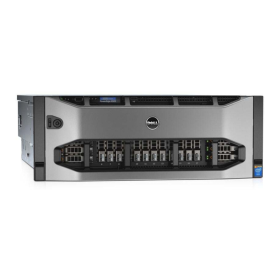
About Your System Front-Panel Features And Indicators Figure 1. Front-Panel Features and Indicators Item Indicator, Button, or Icon Description Connector Power-on indicator, power The power-on indicator lights when the system power is button on. The power button controls the power supply output to the system. -
Page 10: Lcd Panel Features
Item Indicator, Button, or Icon Description Connector Press to toggle the system ID on and off. If the system stops responding during POST, press and hold the system ID button for more than five seconds to enter BIOS progress mode. To reset iDRAC (if not disabled in F2 iDRAC setup), press and hold the button for more than 15 seconds. -
Page 11: Home Screen
• The LCD backlight remains off if LCD messaging is turned off through the iDRAC utility, the LCD panel, or other tools. Figure 2. LCD Panel Features Item Button Description Left Moves the cursor back in one-step increments. Select Selects the menu item highlighted by the cursor. -
Page 12: View Menu
Option Description Set error Select SEL to display LCD error messages in a format that matches the IPMI description in the SEL. This is useful when trying to match an LCD message with an SEL entry. Select Simple to display LCD error messages in a simplified user-friendly description. See System Error Messages for a list of messages in this format. -
Page 13: Pcie Ssd Led Indicators
Drive-Status Condition Indicator Pattern (RAID Only) Blinks green two Identifying drive or preparing for removal times per second Drive ready for insertion or removal NOTE: The drive status indicator remains off until all hard drives are initialized after the system is turned on. Drives are not ready for insertion or removal during this time. Blinks green, amber, Predicted drive failure and off... -
Page 14: Back-Panel Features And Indicators
State Name Slot/Device State Status LED (Green) Status LED (Amber) On for 250 msec Device identify (blink) The device is identifying the Off for 250 msec slot location or is indicating the device has received a Prepare for Removal command from the host operating system. -
Page 15: Nic Indicator Codes
Item Indicator, Button, or Icon Description Connector Serial connector Allows you to connect a serial device to the system. USB connectors (2) Allows you to connect USB devices to the system. The ports are USB 2.0-compliant. PCIe expansion card slots (8 Allows you to connect PCI Express expansion cards. -
Page 16: Power Indicator Codes
Indicator Indicator Code Link and activity The NIC is not connected to the network. indicators are off Link indicator is The NIC is connected to a valid network at its maximum port speed (1 Gbps or 10 Gbps). green Link indicator is The NIC is connected to a valid network at less than its maximum port speed. -
Page 17: Related Documentation
WARNING: See the safety and regulatory information that shipped with your system. Warranty information may be included within this document or as a separate document. NOTE: For all PowerEdge documentation, go to dell.com/poweredgemanuals and enter the system Service Tag to get your system documentation. -
Page 18: Quick Resource Locator
Use the Quick Resource Locator (QRL) to get immediate access to system information and how-to videos. This can be done by visiting dell.com/QRL or by using your smartphone and a model specific QR code located on your Dell PowerEdge system. To try out the QR code, scan the following image. -
Page 19: Using The System Setup And Boot Manager
Using The System Setup and Boot Manager System Setup enables you to manage your system hardware and specify BIOS-level options. The following keystrokes provide access to system features during startup: Keystroke Description Opens the System Setup page. <F2> Enters System Services and starts Lifecycle Controller, <F10>... -
Page 20: Entering System Setup
NOTE: Operating systems must be UEFI-compatible to be installed from the UEFI boot mode. DOS and 32-bit operating systems do not support UEFI and can only be installed from the BIOS boot mode. NOTE: For the latest information on supported operating systems, go to dell.com/ossupport. Entering System Setup Turn on or restart your system. -
Page 21: System Setup Options
System Setup Options System Setup Main Screen NOTE: Press <Alt><F> to reset the BIOS or UEFI settings to their default settings. Menu Item Description System BIOS This option is used to view and configure BIOS settings. iDRAC Settings This option is used to view and configure iDRAC settings. Device Settings This option is used to view and configure device settings. -
Page 22: Memory Settings Screen
Menu Item Description System BIOS Version Displays the BIOS version installed on the system. System Service Tag Displays the system Service Tag. System Manufacturer Displays the name of the system manufacturer. System Manufacturer Displays the contact information of the system manufacturer. Contact Information Memory Settings Screen Menu Item... -
Page 23: Sata Settings Screen
Menu Item Description Adjacent Cache Line Allows you to optimize the system for applications that require high utilization of sequential Prefetch memory access. By default, the Adjacent Cache Line Prefetch option is set to Enabled. You can disable this option for applications that require high utilization of random memory access. Hardware Prefetcher Allows you to enable or disable hardware prefetcher. -
Page 24: Boot Settings Screen
Boot Settings Screen Menu Item Description Boot Mode Allows you to set the boot mode of the system. CAUTION: Switching the boot mode may prevent the system from booting if the operating system is not installed in the same boot mode. If the operating system supports UEFI, you can set this option to UEFI. -
Page 25: Serial Communications Screen
Menu Item Description NOTE: This option is displayed only if IDSDM is installed on the system board. Integrated Network Allows you to enable or disable the integrated network card 1. By default, the Integrated Card 1 Network Card 1 option is set to Enabled. OS Watchdog Timer Allows you to enable or disable the OS watchdog timer. -
Page 26: System Profile Settings Screen
Custom. By default, the System Profile option is set to Performance Per Watt Optimized (DAPC). DAPC is Dell Active Power Controller. NOTE: The following parameters are available only when the System Profile is set to Custom. -
Page 27: System Security Screen
System Security Screen Menu Item Description Intel AES-NI The Intel AES-NI option improves the speed of applications by performing encryption and decryption using the Advanced Encryption Standard Instruction Set and is set to Enabled by default. System Password Allows you to set the system password. This option is read-only if the password jumper is not installed in the system. -
Page 28: Miscellaneous Settings
Miscellaneous Settings Menu Item Description System Time Allows you to set the time on the system. System Date Allows you to set the date on the system. Asset Tag Displays the asset tag and allows you to modify it for security and tracking purposes. Keyboard NumLock Allows you to set whether the system boots with the NumLock enabled or disabled. -
Page 29: Deleting Or Changing An Existing System And/Or Setup Password
To assign a system and/or setup password: To enter System Setup, press <F2> immediately after a power-on or reboot. In the System Setup Main Menu, select System BIOS and press <Enter>. The System BIOS screen is displayed. In the System BIOS screen, select System Security and press <Enter>. The System Security screen is displayed. -
Page 30: Using Your System Password To Secure Your System
Using Your System Password To Secure Your System NOTE: If you have assigned a setup password, the system accepts your setup password as an alternate system password. Turn on or reboot your system. Type your password and press <Enter>. When Password Status is Locked, type the password and press <Enter> when prompted at reboot. If an incorrect system password is entered, the system displays a message and prompts you to re-enter your password. -
Page 31: Using The Boot Manager Navigation Keys
Launch System Setup Enables you to access the System Setup. Launch Lifecycle Enables you to access the Lifecycle Controller menu. controller System Utilities Enables you to access the BIOS Update File Explorer, run the Dell Diagnostics program, and reboot the system. UEFI Boot menu Menu Item Description... -
Page 32: Embedded System Management
Sets a one-time boot option not included in the boot option list. Embedded System Management The Dell Lifecycle Controller provides advanced embedded systems management throughout the server’s lifecycle. The Lifecycle Controller can be started during the boot sequence and can function independently of the operating system. -
Page 33: Installing System Components
Installing System Components Recommended Tools You may need the following items to perform the procedures in this section: • Key to the system keylock • #2 Phillips screwdriver • 10 in-lb. torque tool • Wrist grounding strap connected to ground You may need the following tools for assembling cables for a DC power supply unit (PSU), when available: •... -
Page 34: Installing The Front Bezel
Damage due to servicing that is not authorized by Dell is not covered by your warranty. Read and follow the safety instructions that came with the product. -
Page 35: Opening The System
Opening The System NOTE: It is recommended that you always use a static mat and static strap while working on components inside the system. Turn off the system and attached peripherals, and disconnect the system from the electrical outlet. Rotate the latch release lock counter clockwise to the unlocked position. Lift the latch on top of the system cover and slide the cover toward the back of the system, so that the front hooks and the hook-slots on the back edge of the cover are out of the chassis. -
Page 36: Inside The System
Damage due to servicing that is not authorized by Dell is not covered by your warranty. Read and follow the safety instructions that came with the product. -
Page 37: Chassis Intrusion Switch
Damage due to servicing that is not authorized by Dell is not covered by your warranty. Read and follow the safety instructions that came with the product. -
Page 38: Cable Management Tray
Figure 12. Removing and Installing the Chassis Intrusion Switch chassis intrusion switch NDC riser (riser 1) chassis intrusion switch cable Cable Management Tray The cable management tray is located above the processor heat sinks. It is used to route and manage the cables connecting the storage and expansion cards to various connectors on the backplane. -
Page 39: Installing The Cable Management Tray
Figure 13. Removing and Installing the Cable Management Tray cable tray slot (4) cable tray hook (4) cable tray cover cable tray cover release tab cables (routed) Installing The Cable Management Tray Position the cable management tray above the processor heat sinks. Lower the cable tray and insert the cable tray hooks into the slots on one side of the chassis. - Page 40 Memory bus operating frequency can be 1066 MT/s, 1333 MT/s, and 1600 MT/s depending on: • DIMM type (RDIMM and LRDIMM) • DIMM configuration (number of ranks) • Maximum frequency of the DIMMs • Number of DIMMs populated per channel •...
- Page 41 Figure 14. Memory Socket Locations Memory channels are organized as follows: Processor 1 channel 0: slots A1, A5, and A9 channel 1: slots A2, A6, and A10 channel 2: slots A3, A7, and A11 channel 3: slots A4, A8, and A12 channel 0: slots B1, B5, and B9 channel 1: slots B2, B6, and B10 channel 2: slots B3, B7, and B11...
- Page 42 channel 2: slots E3, E7, and E11 channel 3: slots E4, E8, and E12 channel 0: slots F1, F5, and F9 channel 1: slots F2, F6, and F10 channel 2: slots F3, F7, and F11 channel 3: slots F4, F8, and F12 Processor 4 channel 0: slots G1, G5, and G9 channel 1: slots G2, G6, and G10...
-
Page 43: General Memory Module Installation Guidelines
DIMM DIMMs DIMM Size Operating Frequency (in MT/s) Maximum DIMM Rank/ Type Populated/ Channel Channel (DPC) DDR3 (1.5 V) DDR3 (1.35 V) 32 GB / 64 GB 1600 1333 Quad rank physical 32 GB / 64 GB 1333 and 1066 Not Applicable Quad rank physical General Memory Module Installation Guidelines... -
Page 44: Memory Optimized (Independent Channel) Mode
• Memory modules must be identical in size, speed, and technology. • DIMMs installed in memory sockets with white release tabs must be identical and similar rule applies for sockets with black and green release tabs. This ensures that identical DIMMs are installed in matched pairs - for example, A1 with A2, A3 with A4, A5 with A6, and so on. - Page 45 NOTE: DIMMs populated must be identical for each riser. In the mirroring mode, only one of the two CPUs is populated. NOTE: 64GB LRDIMMs are supported by the system. Table 2. Memory Configurations—Single Riser Memory Mode System DIMM Size Number of Capacity (in (in GB) DIMMs...
- Page 46 Memory Mode System DIMM Size Number of Capacity (in (in GB) DIMMs DIMM Slot Population for CPU 1 ( Riser A and B) 1024 1536 X X X X X X X X X Mirroring and Partial Mirroring X X X X X X 1024 1536...
-
Page 47: Removing A Memory-Riser Blank
Damage due to servicing that is not authorized by Dell is not covered by your warranty. Read and follow the safety instructions that came with the product. -
Page 48: Installing A Memory-Riser Blank
Damage due to servicing that is not authorized by Dell is not covered by your warranty. Read and follow the safety instructions that came with the product. -
Page 49: Installing A Memory Riser
Figure 16. Removing and Installing the Memory Riser memory riser handle memory riser handle lock memory riser guide Installing A Memory Riser Turn off the system, including any attached peripherals, and disconnect the system from the electrical outlet. Open the system. If applicable, remove the memory-riser blank and orange protective cap on the memory riser connector. -
Page 50: Removing Memory Modules From The Memory Riser
Damage due to servicing that is not authorized by Dell is not covered by your warranty. Read and follow the safety instructions that came with the product. - Page 51 Figure 17. Opening and Closing the Memory Riser memory riser release tabs memory riser cover memory riser handle Locate the appropriate memory-module socket(s). To release the memory-module blank from the socket, simultaneously press the ejectors on both ends of the memory module socket.
-
Page 52: Installing Memory Modules
Damage due to servicing that is not authorized by Dell is not covered by your warranty. Read and follow the safety instructions that came with the product. - Page 53 CAUTION: To ensure proper system cooling, memory-module blanks must be installed in any memory socket that is not occupied. Remove memory-module blanks only if you intend to install memory modules in those sockets. Turn off the system, including any attached peripherals, and disconnect the system from the electrical outlet. Open the system.
-
Page 54: Memory Riser And Fan Cage
13. Reconnect the system to its electrical outlet and turn on the system, including any attached peripherals. 14. Press <F2> to enter the System Setup, and check the memory settings. The system should have already changed the value to reflect the newly installed memory. 15. -
Page 55: Installing The Memory Riser And Fan Cage
Figure 21. Removing and Installing the Memory Riser and Fan Cage memory riser and fan cage handle fan cage memory riser and fan cage back handle handle lock cage guides on the side of the chassis Installing The Memory Riser And Fan Cage NOTE: Before installing the memory riser and fan cage, ensure there are no loose cables from the hard-drive backplane. -
Page 56: Hard Drives
Install cooling fans. Close the system. Reconnect the system to its electrical outlet and turn the system on, including any attached peripherals. Hard Drives All hard drives connect to the system board through the hard-drive backplane. Hard drives are supplied in hot- swappable hard-drive carriers that fit in the hard-drive slots. -
Page 57: Removing A Hot-Swap Hard Drive
Damage due to servicing that is not authorized by Dell is not covered by your warranty. Read and follow the safety instructions that came with the product. -
Page 58: Removing A Hard Drive From A Hard-Drive Carrier
CAUTION: To prevent data loss, ensure that your operating system supports hot-swap drive installation. See the documentation supplied with your operating system. CAUTION: When a replacement hot-swappable hard drive is installed and the system is powered on, the hard drive automatically begins to rebuild. Make absolutely sure that the replacement hard drive is blank or contains data that you wish to have over-written. -
Page 59: Installing A Hard Drive Into A Hard-Drive Carrier
Damage due to servicing that is not authorized by Dell is not covered by your warranty. Read and follow the safety instructions that came with the product. -
Page 60: Installing The Optical Drive
Damage due to servicing that is not authorized by Dell is not covered by your warranty. Read and follow the safety instructions that came with the product. -
Page 61: Removing A Cooling Fan
Damage due to servicing that is not authorized by Dell is not covered by your warranty. Read and follow the safety instructions that came with the product. -
Page 62: Installing A Cooling Fan
Damage due to servicing that is not authorized by Dell is not covered by your warranty. Read and follow the safety instructions that came with the product. -
Page 63: Installing The Fan Tray
Figure 27. Removing and Installing the Fan Tray fan tray connector fan tray Installing The Fan tray Align the fan tray with the connector and the screw holes on the system board. Lower the fan tray and ensure that the fan tray connector engages with the connector on the system board. Using a #2 Phillips screwdriver, tighten the fan tray screws (2 screws on the left and 1 screw on the right side) to the system board. -
Page 64: Replacing The Internal Usb Key
Damage due to servicing that is not authorized by Dell is not covered by your warranty. Read and follow the safety instructions that came with the product. -
Page 65: Expansion Card Installation Guidelines
Expansion Card Installation Guidelines Your system supports third Generation 10 PCIe expansion card slots that include one dedicated slot for PERC 9 storage card and one dedicated riser-slot for Network Daughter Card (NDC). Slot 1 connector functions as an x8 connector and can be extended as two x4 slots when the left I/O riser is installed. Slot 9 connector functions as an x16 connector and can be extended as two x8 slots when the right I/O riser is installed. -
Page 66: Removing The Left Expansion Card Riser Blank
Damage due to servicing that is not authorized by Dell is not covered by your warranty. Read and follow the safety instructions that came with the product. -
Page 67: Installing The Left Expansion Card Riser Blank
Damage due to servicing that is not authorized by Dell is not covered by your warranty. Read and follow the safety instructions that came with the product. -
Page 68: Removing The Right Expansion Card Riser Blank
Damage due to servicing that is not authorized by Dell is not covered by your warranty. Read and follow the safety instructions that came with the product. - Page 69 Figure 30. Removing and Installing Expansion-Card Risers 2 and 3 Cage expansion-card riser 2 cage expansion-card riser handle expansion-card riser 3 cage riser panel guide pin plastic guide on VR bracket...
- Page 70 Figure 31. Removing and Installing the Expansion-Card (half-length) from the Expansion-Card Riser 2 expansion-card connector on the riser expansion-card (half-length) expansion-card latch expansion-card riser cage...
- Page 71 Figure 32. Removing and Installing the Expansion-Card (full-length) from the Expansion-Card Riser 2 expansion-card connector on the riser expansion-card (full-length) expansion-card latch expansion-card riser cage To enable the installation of full-length expansion card in expansion-card riser 2 or 3, ensure the metal brackets are removed from the back of the memory cage and fan cage.
- Page 72 Figure 33. Removing The Metal Brackets To Install The Full-Length Expansion Cards memory riser and fan cage left metal bracket right metal bracket Figure 34. Removing and Installing the Expansion-Card from the Expansion-Card Riser 3 expansion-card riser cage expansion-card connector on the riser expansion-card latch expansion-card...
-
Page 73: Installing An Expansion Card Into The Expansion-Card Riser 2 And 3
Damage due to servicing that is not authorized by Dell is not covered by your warranty. Read and follow the safety instructions that came with the product. -
Page 74: Installing The Ndc Riser (I/O Riser 1)
Damage due to servicing that is not authorized by Dell is not covered by your warranty. Read and follow the safety instructions that came with the product. -
Page 75: Network Daughter Card
Damage due to servicing that is not authorized by Dell is not covered by your warranty. Read and follow the safety instructions that came with the product. -
Page 76: Installing The Network Daughter Card
Damage due to servicing that is not authorized by Dell is not covered by your warranty. Read and follow the safety instructions that came with the product. -
Page 77: Replacing An Sd Vflash Card
Damage due to servicing that is not authorized by Dell is not covered by your warranty. Read and follow the safety instructions that came with the product. -
Page 78: Installing The Internal Dual Sd Module
Damage due to servicing that is not authorized by Dell is not covered by your warranty. Read and follow the safety instructions that came with the product. -
Page 79: Removing An Internal Sd Card
Damage due to servicing that is not authorized by Dell is not covered by your warranty. Read and follow the safety instructions that came with the product. -
Page 80: Installing An Internal Sd Card
Damage due to servicing that is not authorized by Dell is not covered by your warranty. Read and follow the safety instructions that came with the product. -
Page 81: Installing The Integrated Storage Controller Card
Damage due to servicing that is not authorized by Dell is not covered by your warranty. Read and follow the safety instructions that came with the product. -
Page 82: Raid Battery
Damage due to servicing that is not authorized by Dell is not covered by your warranty. Read and follow the safety instructions that came with the product. -
Page 83: Installing The Raid Battery
Damage due to servicing that is not authorized by Dell is not covered by your warranty. Read and follow the safety instructions that came with the product. -
Page 84: Installing A Heat Sink Blank
Damage due to servicing that is not authorized by Dell is not covered by your warranty. Read and follow the safety instructions that came with the product. -
Page 85: Removing A Processor
Damage due to servicing that is not authorized by Dell is not covered by your warranty. Read and follow the safety instructions that came with the product. - Page 86 Figure 43. Removing and Installing the Processor Heat Sink heat sink retention screws (4) retention sockets (4) processor CAUTION: The processor is held in its socket under strong pressure. Be aware that the release lever can spring up suddenly if not firmly grasped. 12.
- Page 87 Figure 44. Processor Shield Opening and Closing Lever Sequence processor socket-release lever close-lock symbol processor processor socket-release lever open-lock symbol 14. Rotate the processor shield upward and out of the way. CAUTION: The socket pins are fragile and can be permanently damaged. Be careful not to bend the pins in the socket when removing the processor out of the socket.
-
Page 88: Installing A Processor
Damage due to servicing that is not authorized by Dell is not covered by your warranty. Read and follow the safety instructions that came with the product. -
Page 89: Power Supplies
NOTE: If you are installing two processors, they must be installed in socket CPU1 and CPU2. Turn off the system, including any attached peripherals, and disconnect the system from the electrical outlet. When disconnected from the power source, press and hold the power button for three seconds to fully drain the system of stored power prior to removing the cover. -
Page 90: Hot Spare Feature
Damage due to servicing that is not authorized by Dell is not covered by your warranty. Read and follow the safety instructions that came with the product. -
Page 91: Installing An Ac Power Supply
Damage due to servicing that is not authorized by Dell is not covered by your warranty. Read and follow the safety instructions that came with the product. -
Page 92: Wiring Instructions For A Dc Power Supply
All electrical wiring must comply with applicable local or national codes and practices. Damage due to servicing that is not authorized by Dell is not covered by your warranty. Read and follow all safety instructions that came with the product. -
Page 93: Assembling The Dc Input Power Wires
All electrical wiring must comply with applicable local or national codes and practices. Damage due to servicing that is not authorized by Dell is not covered by your warranty. Read and follow all safety instructions that came with the product. -
Page 94: Removing A Dc Power Supply
All electrical wiring must comply with applicable local or national codes and practices. Damage due to servicing that is not authorized by Dell is not covered by your warranty. Read and follow all safety instructions that came with the product. -
Page 95: Installing A Dc Power Supply
All electrical wiring must comply with applicable local or national codes and practices. Damage due to servicing that is not authorized by Dell is not covered by your warranty. Read and follow all safety instructions that came with the product. -
Page 96: Removing The Power Supply Blank
Removing The Power Supply Blank CAUTION: To ensure proper system cooling, the power supply blank must be installed in the second power supply bay in a non-redundant configuration. Remove the power supply blank only if you are installing a second power supply. -
Page 97: Removing The Power Supply Bay
Damage due to servicing that is not authorized by Dell is not covered by your warranty. Read and follow the safety instructions that came with the product. -
Page 98: Installing The Power Supply Bay
Damage due to servicing that is not authorized by Dell is not covered by your warranty. Read and follow the safety instructions that came with the product. -
Page 99: Installing The Power Distribution Board
Damage due to servicing that is not authorized by Dell is not covered by your warranty. Read and follow the safety instructions that came with the product. -
Page 100: Hard-Drive Backplane
Damage due to servicing that is not authorized by Dell is not covered by your warranty. Read and follow the safety instructions that came with the product. -
Page 101: Removing The Hard-Drive Backplane
Damage due to servicing that is not authorized by Dell is not covered by your warranty. Read and follow the safety instructions that came with the product. - Page 102 Figure 54. Removing and Installing the 2.5 Inch (x4) SAS/SATA Backplane release tab system board miscellaneous signal cable SAS connector hard drive connector backplane hook (4) backplane power cable Figure 55. 2.5 Inch (x4) SAS/SATA Backplane—Front view SAS connector on the backplane hard drive connector backplane hook (4)
- Page 103 Figure 56. 2.5 Inch (x4) SAS/SATA Backplane—Back view backplane power cable system board miscellaneous signal cable Figure 57. Removing and Installing the 2.5 Inch (x24) SAS/SATA Backplane release tab (2) backplane jumper connector backplane jumper connector for the expander backplane power cable daughter card SAS connector hard drive connector...
- Page 104 Figure 58. 2.5 Inch (x24) SAS/SATA Backplane—Front view jumper connector hard drive connector SAS connector hard drive connector backplane loops backplane hook (8) backplane jumper connector Figure 59. 2.5 Inch (x24) SAS/SATA Backplane—Back view backplane power connector 1 backplane power connector 2 system board miscellaneous signal cable...
- Page 105 Figure 60. Removing and Installing the 2.5 Inch (x16) SAS/SATA and (x8) PCIe SSD Backplane release tab (2) backplane jumper connector system board miscellaneous signal cable primary PCIe SSD extender mini-SAS HD connector (4) SAS connector secondary PCIe SSD extender mini-SAS HD connector (4) backplane hook (8) backplane power connector...
- Page 106 backplane hook (8) jumper connector to the expander daughter card Figure 62. Cabling—2.5 Inch (x4) SAS/SATA Backplane with PERC 9 SAS cable connector on the integrated storage integrated storage controller card (PERC 9) controller card system board cable management tray x4 hard drive backplane SAS connector on the backplane...
- Page 107 Figure 63. Cabling—2.5 Inch (x24) SAS/SATA Backplane with PERC 9 SAS (A&B) cable connector on the integrated integrated storage controller card (PERC 9) storage controller card system board cable management tray x24 hard drive backplane SAS B cable connector on the expander daughter card backplane jumper cable connector on the SAS jumper cable connector on the expander...
- Page 108 Figure 64. Cabling—2.5 Inch (x16) SAS/SATA and (x8) PCIe SSD Backplane (left and right side) SAS (A&B) cable connector on the integrated integrated storage controller card storage controller card system board cable management tray secondary PCIe SSD extender mini-SAS HD x24 hard-drive backplane connector (A to D) SAS B cable connector on the expander...
- Page 109 Figure 65. Cabling— x24 Backplane With Dual PERC And Dual SAS Expander Cards SAS cable connector on the primary integrated integrated storage controller card (primary storage controller card card) integrated storage controller card (secondary SAS cable connector on the secondary card) integrated storage controller card x24 hard drive backplane...
-
Page 110: Installing The Hard-Drive Backplane
Damage due to servicing that is not authorized by Dell is not covered by your warranty. Read and follow the safety instructions that came with the product. -
Page 111: Installing The Sas Expander Daughter Card
Damage due to servicing that is not authorized by Dell is not covered by your warranty. Read and follow the safety instructions that came with the product. -
Page 112: Installing The Control Panel Board
Damage due to servicing that is not authorized by Dell is not covered by your warranty. Read and follow the safety instructions that came with the product. -
Page 113: System Board
Damage due to servicing that is not authorized by Dell is not covered by your warranty. Read and follow the safety instructions that came with the product. -
Page 114: Installing The System Board
Damage due to servicing that is not authorized by Dell is not covered by your warranty. Read and follow the safety instructions that came with the product. - Page 115 Close the system. Reconnect the system to its electrical outlet and turn the system on, including any attached peripherals. iDRAC7 version 1.40.40 User's Import your new or existing iDRAC7 Enterprise license. For more information, see Guide , at dell.com/support/manuals.
-
Page 116: Troubleshooting Your System
Damage due to servicing that is not authorized by Dell is not covered by your warranty. Read and follow the safety instructions that came with the product. -
Page 117: Troubleshooting A Serial I/O Device
Damage due to servicing that is not authorized by Dell is not covered by your warranty. Read and follow the safety instructions that came with the product. -
Page 118: Troubleshooting A Damaged System
Damage due to servicing that is not authorized by Dell is not covered by your warranty. Read and follow the safety instructions that came with the product. -
Page 119: Troubleshooting The System Battery
Damage due to servicing that is not authorized by Dell is not covered by your warranty. Read and follow the safety instructions that came with the product. -
Page 120: Troubleshooting Cooling Fans
Damage due to servicing that is not authorized by Dell is not covered by your warranty. Read and follow the safety instructions that came with the product. -
Page 121: Troubleshooting An Internal Usb Key
Damage due to servicing that is not authorized by Dell is not covered by your warranty. Read and follow the safety instructions that came with the product. -
Page 122: Troubleshooting An Optical Drive
Damage due to servicing that is not authorized by Dell is not covered by your warranty. Read and follow the safety instructions that came with the product. -
Page 123: Troubleshooting A Storage Controller
Damage due to servicing that is not authorized by Dell is not covered by your warranty. Read and follow the safety instructions that came with the product. -
Page 124: Troubleshooting Expansion Cards
Damage due to servicing that is not authorized by Dell is not covered by your warranty. Read and follow the safety instructions that came with the product. - Page 125 10. Open the system. 11. Remove the memory risers, cooling fans, and memory riser and fan cage. 12. If your system has four processors, remove all processors except for processor 1 and processor 2. 13. Install the memory riser and fan cage, cooling fans and memory risers. 14.
-
Page 126: Using System Diagnostics
Using System Diagnostics If you experience a problem with your system, run the system diagnostics before contacting Dell for technical assistance. The purpose of running system diagnostics is to test your system hardware without requiring additional equipment or risking data loss. If you are unable to fix the problem yourself, service and support personnel can use the diagnostics results to help you solve the problem. - Page 127 Menu Description System Health Provides the current overview of the system performance. Event Log Displays a time-stamped log of the results of all tests run on the system. This is displayed if at least one event description is recorded.
-
Page 128: Jumpers And Connectors
Jumpers And Connectors System Board Jumper Settings For information on resetting the password jumper to disable a password, see Disabling A Forgotten Password. Table 5. System Board Jumper Settings Jumper Setting Description PWRD_EN The password feature is enabled (pins 4–6). (default) The password feature is disabled (pins 2–4). -
Page 129: System Board Connectors
System Board Connectors Figure 69. System Board Jumpers and Connectors Item Connector Description J_VIDEO VGA connector JA_IDRAC_RG45 IDRAC connector INT_STORAGE/ J_PERC Integrated storage controller card connector J_PCIE_SLOT1 Left I/O Riser Connector (Optional) IO_RISER1/J_NDC_RISER NDC Riser Connector J_PCIE_SLOT 3–8 Expansion-card connectors... - Page 130 Item Connector Description J_PCIE_SLOT9 Right I/O Riser Connector (Optional) USB1/USB2 J_USB USB connector J_SERIAL Serial connector JA_CYC System Identification connector W_CYC_ID System Identification button connector J_SATA_PWR_BC SATA power Backplane connector SATA_B SATA B connector SATA_C SATA C connector SATA_A SATA A connector J_USB_INT Internal USB connector CPU4...
- Page 131 Figure 70. Expander Daughter Card board Jumpers and Connectors (Unified Mode) Item Connector Description J_SAS_A1 SAS A1 connector J_SAS_A SAS A connector J_XCEDE_SAS1 SAS 1 connector J_XCEDE_SAS2 SAS 2 connector J_SAS_B SAS B connector J_SAS_B1 SAS B1 connector Figure 71. Expander Daughter Card board Jumpers and Connectors (Performance Mode)
-
Page 132: Disabling A Forgotten Password
Damage due to servicing that is not authorized by Dell is not covered by your warranty. Read and follow the safety instructions that came with the product. -
Page 133: Technical Specifications
Technical Specifications Processor Processor type Two or Four Intel Xeon Processor E7-8800/4800/2800 v2 product family Power AC Power Supply (per power supply) Wattage 750 W, 1100 W, or 1600 W (when available) NOTE: Your system supports a maximum of two 1600 W power supplies. - Page 134 Expansion Bus (Slot 2/2) One full-height, half-length x4 link (Slot 3) One full-height, half-length x8 link (Slot 4) One full-height, full-length x16 link NOTE: To use slots 6 through 10, all four processors must be installed. (Slot 5) One full-height, half-length x16 link (Slot 6) One full-height, half-length x16 link (Slot 7) One full-height, half-length x16 link (Slot 8) One full-height, half-length x16 link...
- Page 135 Up to sixteen 2.5 inch, internal, hot-swappable SAS drives and up systems to eight Dell PowerEdge Express Flash devices (PCIe SSDs) hard drives in hard-drive slots 0 through 4 (bay 1), 0 through 4 (bay 2), and 0 through 15 (bay 3) for SAS/SATA with 2 PCIe Extender Cards, one Unified Mode Daughter Card, and one PERC 9 Card.
- Page 136 The operating temperature specified is for a maximum altitude of 3050 m (10,000 ft). • 130 W (4 core) processor is not supported. • Redundant power supplies are required. • Non Dell qualified peripheral cards and/or peripheral cards greater than 25 W are not supported.
- Page 137 NOTE: Your system is capable of 40 °C and 45 °C excursion operation for fresh air cooled data centers. NOTE: For additional information about environmental measurements for specific system configurations, see dell.com/environmental_datasheets. Temperature Maximum Temperature Gradient (Operating and 20 °C/h (36 °F/h)
- Page 138 NOTE: This section defines the limits to help avoid IT equipment damage and/or failure from particulates and gaseous contamination. If it is determined that levels of particulates or gaseous pollution are beyond the limits specified below and are the reason for the damage and/or failures to your equipment, it may be necessary for you to re-mediate the environmental conditions that are causing the damage and/or failures.
-
Page 139: System Messages
System Messages LCD Messages NOTE: Applicable only if your system has an LCD display. The LCD messages consist of brief text messages that refer to events recorded in the System Event Log (SEL). For information on the SEL and configuring system management settings, see the systems management software documentation. - Page 140 Error Code Message Information AMP0302 name > current is greater than the upper warning Message The system board < threshold. name > current is outside of the optimum range. Details System board < Action Review system power policy. Check system logs for power related failures. Review system configuration changes.
- Page 141 Error Code Message Information ASR0003 Message The watchdog timer power cycled the system. Details The operating system or an application failed to communicate within the time-out period. The system was power-cycled. Action Check the operating system, application, hardware, and system event log for exception events.
- Page 142 Error Code Message Information Action Review the technical specifications for supported processor types. CPU0010 number > is throttled. Message CPU < Details The CPU is throttled due to thermal or power conditions. Action Review system logs for power or thermal exceptions. CPU0023 number >...
- Page 143 Error Code Message Information Turn off the system and remove input power for one minute. Ensure the processor is seated correctly. Reapply input power and turn on the system. If the issue persists, see Getting Help. CPU0702 Message CPU bus parity error detected. LCD Message CPU bus parity error detected.
- Page 144 Error Code Message Information If the issue persists, see Getting Help. FAN0000 number > RPM is less than the lower warning threshold. Message Fan < Details Fan operating speed is out of range. Action Remove and reinstall the fan. If the issue persists, see Getting Help.
- Page 145 Error Code Message Information Action Check if the cable is present, then reinstall or reconnect. MEM0000 Message Persistent correctable memory errors detected on a memory device location >. at location(s) < Details This is an early indicator of a possible future uncorrectable error. Action Re-seat the memory modules.
- Page 146 Error Code Message Information location >. Power cycle system. LCD Message Memory mirror lost on < Details The memory may not be seated correctly, misconfigured, or has failed. Action Check the memory configuration. Re-seat the memory modules. If the issue persists, see Getting Help.
- Page 147 Error Code Message Information Action Cycle input power, update component drivers, if device is removable, reinstall the device. PCI1320 Message A bus fatal error was detected on a component at bus bus >device< device >function < func >. < bus > device < device > function < func >. Power LCD Message Bus fatal error on bus <...
- Page 148 Error Code Message Information number > removed from disk drive bay < bay >. Check drive. LCD Message Drive < Details The controller detected that the drive was removed. Action Verify drive installation. Re-seat the failed drive. If the issue persists, Getting Help.
- Page 149 Error Code Message Information PSU0006 number > type mismatch. Message Power supply < LCD Message Power supply < number > is incorrectly configured. Check PSU. Details Power supplies should be of the same input type and power rating. Action Install matched power supplies and review proper configuration in this manual.
- Page 150 Error Code Message Information PSU0034 number >. Message An under voltage fault detected on power supply < LCD Message An under voltage fault detected on PSU < number >. Check power source. Details This failure may be the result of an electrical issue with cables or subsystem components in the system.
- Page 151 Error Code Message Information PSU1201 Message Power supply redundancy is lost. Details The power supply tries to operate in a degraded state. System Performance and power redundancy may be degraded or lost. Action Check input power. Reinstall the power supply. If the issue persists, Getting Help.
- Page 152 Error Code Message Information Details An error was reported during a SD card read or write. Action Reseat the flash media. If the problem persists, see Getting Help. RFM1014 name > is write protected. Message Removable Flash Media < name > is write protected. Check SD Card. LCD Message Removable Flash Media <...
- Page 153 Error Code Message Information SEC0031 Message The chassis is open while the power is on. LCD Message Intrusion detected. Check chassis cover. Details The chassis is open. System performance may be degraded, and security may be compromised. Action Close the chassis. Check system logs. SEC0033 Message The chassis is open while the power is off.
- Page 154 Error Code Message Information Action Re-configure system to the minimum supported configuration. If issues persists, contact support. TMP0118 Message The system inlet temperature is less than the lower warning threshold. LCD Message System inlet temperature is outside of range. Details Ambient air temperature is too cool.
-
Page 155: Warning Messages
Error Code Message Information Action Review system logs for power supply exceptions. Re-configure the system to minimum configuration, inspect and reinstall system cables. If the issue persists, see Getting Help. Warning Messages A warning message alerts you to a possible problem and prompts you to respond before the system continues a task. For example, before you format a hard drive, a message warns you that you may lose all data on the hard drive. -
Page 156: Getting Help
Service Tag are found on the front of a physical DR Series system by pulling out the information tag. This can also be found on the support tab in the GUI. This information is used by Dell to route support calls to the appropriate personnel. -
Page 157: Documentation Feedback
Documentation feedback If you have feedback for this document, write to documentation_feedback@dell.com. Alternatively, you can click on the Feedback link in any of the Dell documentation pages, fill out the form, and click Submit to send your feedback.