Table of Contents
Advertisement
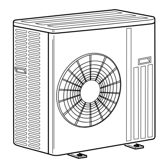
SPLIT-TYPE AIR CONDITIONERS
OUTDOOR UNIT
SERVICE MANUAL
Models
MUZ-GA50VA -
MUZ-GA60VA -
MUZ-GA60VA -
MUZ-GA60VA -
MUZ-GA71VA -
MUZ-GA71VA -
NOTE:
• RoHS compliant products have <G> mark on the spec name plate.
For servicing of RoHS compliant products, refer to the RoHS Parts List.
• Contents of SERVICE FUNCTIONS (10) have been removed.
HFC
utilized
R410A
E1
E1
E2
E3
E1
E2
CONTENTS
1. TECHNICAL CHANGES ··································· 3
2. PART NAMES AND FUNCTIONS ····················· 6
3. SPECIFICATION ················································ 6
4. NOISE CRITERIA CURVES ······························ 7
5. OUTLINES AND DIMENSIONS ························ 8
6. WIRING DIAGRAM ············································ 9
7. REFRIGERANT SYSTEM DIAGRAM ············· 12
8. PERFORMANCE CURVES ····························· 15
9. ACTUATOR CONTROL ··································· 26
10. SERVICE FUNCTIONS ···································· 27
11. TROUBLESHOOTING ····································· 27
12. DISASSEMBLY INSTRUCTIONS ···················· 46
13. PARTS LIST ····················································· 50
14. RoHS PARTS LIST ·········································· 52
• Errors in TROUBLESHOOTING have
been corrected.
Please void OB389 REVISED EDITION-G.
No. OB389
REVISED EDITION-H
Indoor unit service manual
MSZ-GA•VA Series (OB388)
Advertisement
Table of Contents
Troubleshooting

Related Manuals for Mitsubishi Electric MUZ-GA50VA-E1


Summary of Contents for Mitsubishi Electric MUZ-GA50VA-E1
-
Page 1: Table Of Contents
Revision H: • Errors in TROUBLESHOOTING have been corrected. SPLIT-TYPE AIR CONDITIONERS Please void OB389 REVISED EDITION-G. OUTDOOR UNIT No. OB389 REVISED EDITION-H utilized SERVICE MANUAL R410A Models MUZ-GA50VA - MUZ-GA60VA - MUZ-GA60VA - MUZ-GA60VA - MUZ-GA71VA - MUZ-GA71VA - Indoor unit service manual MSZ-GA•VA Series (OB388) CONTENTS... -
Page 2: Revision H
Use the specifi ed refrigerant only Never use any refrigerant other than that specified. Doing so may cause a burst, an explosion, or fire when the unit is being used, serviced, or disposed of. Correct refrigerant is specified in the manuals and on the spec labels provided with our products. We will not be held responsible for mechanical failure, system malfunction, unit breakdown or accidents caused by failure to follow the instructions. -
Page 3: Technical Changes
TECHNICAL CHANGES MUZ-A18YV - MUZ-GA50VA - MUZ-A24YV - MUZ-GA60VA - MUZ-A26YV - MUZ-GA71VA - 1. Indication of capacity has been changed. (BTU base kW base) 2. Outdoor electronic control P.C. board has been changed. 3. Noise filter P.C. board has been changed. 4. - Page 4 New Specification Current Specification The incompatible refrigeration oil easily separates from Since refrigerant and refrigeration oil are compatible, refrigerant and is in the upper layer inside the suction muffler. refrigeration oil goes back to the compressor through the Raising position of the oil back hole enables to back the lower position oil back hole.
- Page 5 2. Refrigerant piping Specifications Use the refrigerant pipes that meet the following specifications. Outside diameter Wall Pipe Insulation material thickness 6.35 0.8 mm For liquid Heat resisting foam plastic 0.8 mm 9.52 Specific gravity 0.045 Thickness 8 mm 0.8 mm 12.7 For gas 1.0 mm...
-
Page 6: Part Names And Functions
PART NAMES AND FUNCTIONS MUZ-GA50VA MUZ-GA60VA MUZ-GA71VA ACCESSORIES Air inlet Drain socket (back and side) Drain cap Ø33 Piping Drain hose Air outlet Drain outlet SPECIFICATION MUZ-GA71VA Outdoor model MUZ-GA50VA MUZ-GA60VA Cooling Heating Heating Function Cooling Heating Cooling Single phase Single phase Single phase Power supply... -
Page 7: Noise Criteria Curves
Specifications and rated conditions of main electric parts Model MUZ-GA50VA MUZ-GA60VA MUZ-GA71VA Item Smoothing capacitor (CB1,2,3) 560μF 450V Current transformer (CT1,2) ETQ19Z68AY Current transformer (CT61) ETQ19Z53AY Fuse (F64) 250V 2A Fuse (F801) 250V 3.15A Fuse (F911) 250V 1A Intelligent power module (HC930) PS21661-RZ High pressure switch... -
Page 8: Outlines And Dimensions
OUTLINES AND DIMENSIONS MUZ-GA50VA Unit: mm MUZ-GA60VA MUZ-GA71VA REQUIRED SPACE Open as a rule 500 mm or more if the front and both sides are open 100 mm or more 200 mm or more if 100 mm or more there are obstacles to both sides Open as a rule 500 mm or more if the back,... -
Page 9: Wiring Diagram
WIRING DIAGRAM MUZ-GA50VA MUZ-GA60VA - MUZ-GA60VA -... - Page 10 MUZ-GA60VA -...
- Page 11 MUZ-GA71VA...
-
Page 12: Refrigerant System Diagram
REFRIGERANT SYSTEM DIAGRAM MUZ-GA50VA Unit: mm MUZ-GA60VA - Refrigerant pipe Ø12.7 (MUZ-GA50VA) Muffler (with heat insulator) Ø15.88 (MUZ-GA60VA) #100 4-way valve Stop valve (with service port) Outdoor Discharge Flared connection heat Ambient temperature exchanger temperature thermistor Defrost thermistor RT62 thermistor RT65 RT61 Compressor... - Page 13 MUZ-GA60VA - Unit: mm Refrigerant pipe Ø15.88 Muffler (with heat insulator) #100 4-way valve Stop valve High-pressure (with service port) Outdoor switch Discharge Flared connection heat Ambient temperature exchanger temperature thermistor Defrost thermistor RT62 thermistor RT65 RT61 Compressor Outdoor heat exchanger temperature thermistor...
- Page 14 MAX. REFRIGERANT PIPING LENGTH and MAX. HEIGHT DIFFERENCE Refrigerant piping : m Piping size O.D : mm Max. Height Model Max. length difference Liquid MUZ-GA50VA 12.7 6.35 MUZ-GA60VA 15.88 MUZ-GA71VA 9.52 Indoor unit Max. Height difference Refrigerant Piping Max. length Outdoor unit ADDITIONAL REFRIGERANT CHARGE (R410A: g) Refrigerant piping length (one way)
-
Page 15: Performance Curves
PERFORMANCE CURVES MUZ-GA50VA MUZ-GA60VA MUZ-GA71VA The standard specifications apply only to the operation of the air conditioner under normal conditions. Since operating condi- tions vary according to the areas where these units are installed, the following information has been provided to clarify the operating characteristics of the air conditioner under the conditions indicated by the performance curve. - Page 16 24.1 23.4 27.9 22.3 21.6 25.7 20.4 19.8 23.6 18.5 18.0 21.4 16.7 16.2 19.3 14.8 14.4 17.2 13.0 12.6 15.0 11.1 10.8 12.9 Outdoor intake air Wet-bulb temperature (°C) Outdoor intake air Wet-bulb temperature (°C) NOTE: The above broken lines are for the heating operation without any frost and defrost operation.
- Page 17 8-3. TEST RUN OPERATION (How to operate fixed-frequency operation) 1. Press EMERGENCY OPERATION switch to COOL or HEAT mode (COOL: Press once, HEAT: Press twice). 2. Test run operation starts and continues to operate for 30 minutes. 3. Compressor operates at rated frequency in COOL mode or 58Hz in HEAT mode. 4.
-
Page 18: Heat Operation
HEAT operation Condition: Indoor Outdoor Dry bulb temperature (ºC) 20.0 20.0 Wet bulb temperature (ºC) 14.5 14.5 Operation: TEST RUN OPERATION (refer to 8-3.) MUZ-GA50VA 10.0 25(°C) Ambient temperature(°C) MUZ-GA60VA MUZ-GA71VA 16.0 12.0 15.0 11.0 14.0 10.0 13.0 12.0 11.0 10.0 25(°C) 25(°C) - Page 19 PERFORMANCE DATA COOL operation at Rated frequency MSZ-GA50VA: MUZ-GA50VA CAPACITY:5.0(kW) SHF:0.65 INPUT:1460(W) OUTDOOR DB(°C) INDOOR INDOOR WB(°C) DB(°C) SHC SHF INPUT SHC SHF INPUT SHC SHF INPUT SHC SHF INPUT 5.88 2.76 0.47 1200 5.63 2.64 0.47 1260 5.40 2.54 0.47 1320 5.20 2.44 0.47 1380 6.13 2.14 0.35...
- Page 20 PERFORMANCE DATA COOL operation at Rated frequency MSZ-GA50VA: MUZ-GA50VA CAPACITY: 5.0(kW) SHF: 0.65 INPUT: 1460(W) OUTDOOR DB(°C) INDOOR INDOOR WB(°C) DB(°C) SHC SHF INPUT SHC SHF INPUT SHC SHF INPUT SHC SHF INPUT 4.90 2.30 0.47 1470 4.50 2.12 0.47 1560 4.33 2.03 0.47 1590 4.15 1.95 0.47...
- Page 21 PERFORMANCE DATA COOL operation at Rated frequency MSZ-GA60VA: MUZ-GA60VA CAPACITY: 6.0(kW) SHF: 0.64 INPUT: 1930(W) OUTDOOR DB(°C) INDOOR INDOOR WB(°C) DB(°C) SHC SHF INPUT SHC SHF INPUT SHC SHF INPUT SHC SHF INPUT 6.24 2.87 0.46 1794 7.05 7.05 3.24 0.46 1560 6.75 3.11 0.46 1638...
- Page 22 PERFORMANCE DATA COOL operation at Rated frequency MSZ-GA60VA: MUZ-GA60VA CAPACITY:6.0(kW) SHF:0.64 INPUT:1930(W) OUTDOOR DB(°C) INDOOR INDOOR WB(°C) DB(°C) SHC SHF INPUT SHC SHF INPUT SHC SHF INPUT SHC SHF INPUT 5.88 2.70 0.46 1911 5.40 2.48 0.46 2028 5.19 2.39 0.46 2067 4.98 2.29 0.46 2106 6.18 2.10 0.34...
- Page 23 PERFORMANCE DATA COOL operation at Rated frequency MSZ-GA71VA: MUZ-GA71VA CAPACITY:7.1(kW) SHF:0.63 INPUT:2420(W) OUTDOOR DB(°C) INDOOR INDOOR WB(°C) DB(°C) SHC SHF INPUT SHC SHF INPUT SHC SHF INPUT SHC SHF INPUT 8.34 3.75 0.45 1952 7.99 3.59 0.45 2050 7.67 3.45 0.45 2147 7.38 3.32 0.45 2245...
- Page 24 PERFORMANCE DATA COOL operation at Rated frequency MSZ-GA71VA: MUZ-GA71VA CAPACITY:7.1(kW) SHF:0.63 INPUT:2420(W) OUTDOOR DB(°C) INDOOR INDOOR WB(°C) DB(°C) SHC SHF INPUT SHC SHF INPUT SHC SHF INPUT SHC SHF INPUT 6.96 3.13 0.45 2391 6.39 2.88 0.45 2538 6.14 2.76 0.45 2586 5.89 2.65 0.45 2635...
- Page 25 PERFORMANCE DATA HEAT operation at Rated frequency MSZ-GA50VA : MUZ-GA50VA CAPACITY:5.9(kW) INPUT:1630(W) OUTDOOR WB(°C) INDOOR DB(°C) INPUT INPUT INPUT INPUT INPUT INPUT INPUT 3.72 1099 4.48 1318 5.25 1487 6.02 1606 6.79 1707 7.49 1758 8.26 1791 3.54 1183 4.25 1403 5.02 1555...
-
Page 26: Actuator Control
ACTUATOR CONTROL MUZ-GA50VA MUZ-GA60VA MUZ-GA71VA 9-1. OUTDOOR FAN MOTOR CONTROL The fan motor turns ON/OFF, interlocking with the compressor. [ON] The fan motor turns ON 5 seconds before the compressor starts up. [OFF] The fan motor turns OFF 15 seconds after the compressor has stopped running. 5 seconds 15 seconds Compressor... -
Page 27: Service Functions
SERVICE FUNCTIONS Contents of “SERVICE FUNCTIONS” have been removed. TROUBLESHOOTING MUZ-GA50VA MUZ-GA60VA MUZ-GA71VA 11-1. CAUTIONS ON TROUBLESHOOTING 1. Before troubleshooting, check the following 1) Check the power supply voltage. 2) Check the indoor/outdoor connecting wire for miswiring. 2. Take care of the following during servicing 1) Before servicing the air conditioner, be sure to turn OFF the main unit first with the remote controller, and after confirming the horizontal vane is closed, turn OFF the breaker and/or disconnect the power plug. -
Page 28: Failure Mode Recall Function
11-2. FAILURE MODE RECALL FUNCTION Outline of the function This air conditioner can memorize the abnormal condition which has occurred once. Even though LED indication listed on the troubleshooting check table (11-4.) disappears, the memorized failure details can be recalled. This mode is very useful when the unit needs to be repaired for the abnormality which does not recur. - Page 29 2. Flow chart of the detailed outdoor unit failure mode recall function Operational procedure The outdoor unit might be abnormal. Confirm if outdoor unit is abnormal according to the following procedures. Confirm that the remote controller is in the failure mode recall function.
- Page 30 3. Outdoor failure mode table LED indication The left lamp of Indoor/outdoor Abnormal point Remedy OPERATION INDICAOR (Outdoor P.C. board) Condition unit failure mode (Failure mode/protection) recall function lamp(Indoor unit) LED 1 LED 2 None (Normal) 2-time flash Outdoor power system Lighting Lighting Overcurrent protection stop is •...
- Page 31 LED indication The left lamp of Indoor/outdoor Abnormal point (Outdoor P.C. board) Condition Remedy OPERATION INDICATOR unit failure mode (Failure mode/protection) recall function lamp(Indoor unit) LED 1 LED 2 Communication error 11-time flash Communication error occurs between Lighting 6 times •...
- Page 32 11-3. INSTRUCTION OF TROUBLESHOOTING If blinking of OPERATION INDICATOR lamp cannot be checked, it can be checked Start with failure mode recall function. OPERATION Indoor unit Indoor unit INDICATOR Indoor unit operates. Operates. does not receive lamp on the indoor Outdoor unit does not Outdoor unit the signal from...
-
Page 33: Troubleshooting Check Table
11-4. TROUBLESHOOTING CHECK TABLE Indication Symptom Abnormal point/Condition Condition Remedy LED1(Red) LED2(Yellow) Outdoor unit • Check the connection of the compressor connecting wire. does not Overcurrent protection stop is continuously performed 3 times within 1 • Refer to 11-6. "How to check inverter/compressor". operate. - Page 34 Indication No. Symptom Abnormal point/Condition Condition Remedy LED1(Red) LED2(Yellow) These symptoms do not mean any abnormality of the product, Outdoor unit Primary current protection The input current exceeds 15A. Once Lighting operates. but check the following points. Secondary current protection The current of the compressor exceeds 15A.
- Page 35 11-5. TROUBLE CRITERION OF MAIN PARTS MUZ-GA50VA MUZ-GA60VA MUZ-GA71VA Part name Check method and criterion Figure Defrost thermistor (RT61) Measure the resistance with a tester. Ambient temperature thermistor (RT65) Refer to 11-7. “Test point diagram and voltage”, 1. “Outdoor electronic control P.C.
- Page 36 11-6. TROUBLESHOOTING FLOW Outdoor unit does not operate. Check of power supply Check the connecting of parts of main power supply circuit. Turn ON power supply. Is there voltage of 230 VAC in the Check the power supply cable. power supply terminal block? Is the output voltage from the noise Replace the noise Is fuse (F64) blown?
-
Page 37: Outdoor Unit Does Not Operate
• When unit cannot operate neither by the remote controller nor by EMERGENCY OPERATION switch. Indoor unit does not operate. • When OPERATION INDICATOR lamp flashes ON and OFF every 0.5-second. Outdoor unit does not operate. How to check mis-wiring and serial signal error (when outdoor unit does not work) Turn OFF the power supply. - Page 38 The cooling operation or heating operation does not operate. Check of R.V. coil • When heating operation does not work. 1. Disconnect the lead wire leading to the compressor. 2. 3 minutes after turning ON the power supply, start EMERGENCY OPERATION in HEAT mode.
- Page 39 • When cooling, heat exchanger of non-operating indoor unit frosts. • When heating, non-operating indoor unit gets warm. Check of LEV Turn ON power supply to the outdoor unit after checking LEV coil is mounted to the LEV body securely. Is "click - click"...
- Page 40 • When OPERATION INDICATOR lamp flashes 6-time. • When thermistor is abnormal. Check of outdoor thermistors Disconnect the connector in the outdoor electronic control P.C. board or the outdoor power board Replace the thermistor. (see below table), and measure the resistance of thermistor. Is the thermistor normal? (Refer to 11-7.1.) When RT64 is abnormal, replace the outdoor power...
- Page 41 • When the operation frequency does not go up from lowest frequency. Check of HPS MUZ-GA60VA MUZ-GA71VA 1. Disconnect the connector CN681 in the electronic control P.C. board. 2. Check the resistance of HPS 1 minute after the outdoor unit power supply was turned OFF. Infinity Check the resistance between Replace HPS.
- Page 42 Electromagnetic noise enters into TV sets or radios Is the unit earthed? Earth the unit. Is the distance between the Extend the distance between antennas and the indoor the antennas and the indoor unit within 3m, or is the unit, and/or the antennas and distance between the the outdoor unit.
- Page 43 11-7. TEST POINT DIAGRAM AND VOLTAGE 1. Outdoor electronic control P.C. board MUZ-GA50VA MUZ-GA60VA MUZ-GA71VA Defrost thermistor (RT61) Ambient temperature thermistor (RT65) Discharge temperature thermistor (RT62) Outdoor heat exchanger temperature thermistor (RT68) Fin temperature thermistor (RT64) 100 110 120 10 20 30 40 50 60 70 80 Temperature (°C) Temperature (°C) Temperature (°C)
- Page 44 2. Noise filter P.C. board MUZ-GA50VA MUZ-GA60VA MUZ-GA71VA CN901 To electronic CN902 CN903 control To power To power P.C. board board board 230 VAC Input CN912 R.V. coil 230 VAC 230 VAC 230 VAC Output Output F64 FUSE F911 FUSE NR64 VARISTOR T2AL250V T1AL250V...
- Page 45 3. Outdoor power board MUZ-GA50VA MUZ-GA60VA MUZ-GA71VA Connect to the compressor Voltage among phases: 5 V to 180 V 325-370 VDC Connect to the earth Output (Red) Connect to the controller board (–) (+)1-5(–): Signal transmission (To electronic control P.C. board) (White) 5 VDC pulse wave (+)2-5(–): Zero cross signal...
-
Page 46: Disassembly Instructions
DISASSEMBLY INSTRUCTIONS <"Terminal with locking mechanism" Detaching points> The terminal which has the locking mechanism can be detached as shown below. There are two types ( Refer to (1) and (2)) of the terminal with locking mechanism. The terminal without locking mechanism can be detached by pulling it out. Check the shape of the terminal before detaching. - Page 47 OPERATING PROCEDURE PHOTOS 2. Removing the inverter assembly, inverter P.C. board Photo 4 and power board Screws of the power board assembly (1) Remove the top panel, cabinet and service panel. (Refer to 1.) (2) Remove the back panel.(Refer to 1.) (3) Disconnect the following connectors;...
- Page 48 OPERATING PROCEDURE PHOTOS 4. Removing the defrost thermistor, discharge temper- Photo 5 ature thermistor, outdoor heat exchanger tempera- ture thermistor and ambient temperature thermistor Discharge temperature thermistor (1) Remove the top panel, cabinet and service panel. (Refer to 1.) (2) Remove the back panel. (Refer to 1.) (3) Disconnect the following connectors;...
- Page 49 OPERATING PROCEDURE PHOTOS 6. Removing the compressor and 4-way valve Photo 8 (1) Remove the top panel, cabinet and service panel. (Refer to 1.) (2) Remove the back panel. (Refer to 1.) (3) Remove the inverter assembly. (Refer to 2.) (4) Recover gas from the refrigerant circuit.
-
Page 50: Parts List
PARTS LIST (non-RoHS compliant) MUZ-GA50VA MUZ-GA60VA MUZ-GA71VA 13-1. OUTDOOR UNIT STRUCTURAL PARTS, ELECTRICAL PARTS AND FUNCTIONAL PARTS 13-2. ACCESSORY... - Page 51 PARTS LIST (non-RoHS compliant) MUZ-GA50VA MUZ-GA60VA MUZ-GA71VA 13-1. OUTDOOR UNIT STRUCTURAL PARTS, ELECTRICAL PARTS AND FUNCTIONAL PARTS Part number that is circled is not shown in the illustration. Q'ty/unit Symbol Part No. Part Name Remarks in Wiring MUZ-GA50 MUZ-GA60 MUZ-GA71 Diagram VA - VA -...
-
Page 52: Rohs Parts List
RoHS PARTS LIST (RoHS compliant) MUZ-GA50VA MUZ-GA60VA MUZ-GA71VA 14-1. OUTDOOR UNIT STRUCTURAL PARTS, ELECTRICAL PARTS AND FUNCTIONAL PARTS... - Page 53 RoHS PARTS LIST (RoHS compliant) MUZ-GA50VA MUZ-GA60VA MUZ-GA71VA 14-1. OUTDOOR UNIT STRUCTURAL PARTS, ELECTRICAL PARTS AND FUNCTIONAL PARTS Part number that is circled is not shown in the illustration. Q'ty/unit Symbol MUZ-GA50 MUZ-GA60 MUZ-GA71 Remarks Part No. Part Name in Wiring VA - VA - VA -...
- Page 54 E12 444 705 DRAIN CAP HEAD OFFICE: TOKYO BLDG., 2-7-3, MARUNOUCHI, CHIYODA-KU, TOKYO 100-8310, JAPAN Copyright 2005 MITSUBISHI ELECTRIC ENGINEERING CO., LTD Distributed in Jun. 2011. No. OB389 REVISED EDITION-H Distributed in Jun. 2010. No. OB389 REVISED EDITION-G 6 Distributed in Sep. 2007. No. OB389 REVISED EDITION-F 6 Distributed in Jul.