Table of Contents
Advertisement
SPLIT-TYPE, HEAT PUMP AIR CONDITIONERS
OUTDOOR UNIT
SERVICE MANUAL
Wireless type
Models
MUZ-GA25VA -
MUZ-GA25VA -
MUZ-GA25VA -
MUZ-GA25VA -
MUZ-GA35VA -
MUZ-GA35VA -
MUZ-GA25VAH -
MUZ-GA25VAH -
MUZ-GA25VAH -
MUZ-GA25VAH -
MUZ-GA35VAH -
MUZ-GA35VAH -
NOTE:
RoHS compliant products have <G> mark on the spec name plate.
For servicing of RoHS compliant products, refer to the RoHS Parts List.
E1
E2
E3
E4
E1
E2
E1
E2
E3
E4
E1
E2
CONTENTS
1. TECHNICAL CHANGES ····································4
2. PART NAMES AND FUNCTIONS······················8
3. SPECIFICATION·················································9
4. NOISE CRITERIA CURVES ·····························11
5. OUTLINES AND DIMENSIONS ·······················12
6. WIRING DIAGRAM ··········································13
7. REFRIGERANT SYSTEM DIAGRAM ··············19
8. PERFORMANCE CURVES ······························21
9. ACTUATOR CONTROL····································29
10. SERVICE FUNCTIONS·····································30
11. TROUBLESHOOTING ······································30
12. DISASSEMBLY INSTRUCTIONS·····················51
13. PARTS LIST······················································54
14. RoHS PARTS LIST···········································58
Revision:C
MUZ-GA25VA(H)-
has been added.
E4
Please void OB379 REVISED EDITION-B.
No. OB379
HFC
REVISED EDITION-C
utilized
R410A
Indoor unit service manual
MSZ-GA•VA Series (OB378)
MSZ-CB•VA Series (OB441)
Advertisement
Table of Contents
Troubleshooting

Related Manuals for Mitsubishi Electric MUZ-GA25VA


Summary of Contents for Mitsubishi Electric MUZ-GA25VA
-
Page 1: Table Of Contents
SPLIT-TYPE, HEAT PUMP AIR CONDITIONERS Please void OB379 REVISED EDITION-B. OUTDOOR UNIT No. OB379 SERVICE MANUAL REVISED EDITION-C utilized R410A Wireless type Models MUZ-GA25VA - MUZ-GA25VA - MUZ-GA25VA - MUZ-GA25VA - MUZ-GA35VA - MUZ-GA35VA - MUZ-GA25VAH - MUZ-GA25VAH - MUZ-GA25VAH - MUZ-GA25VAH - Indoor unit service manual MSZ-GA•VA Series (OB378) - Page 2 Revision:A •Alternative inverter P.C.board has been added(Refer to 11-7.1. Inverter P.C.board (Alternative)). FUSE F901 has been equipped to MUZ-GA35. Model 6. Wiring diagram 11-6.N Check of inverter P.C.board MUZ-GA25VA No change No change MUZ-GA25VAH MUZ-GA35VA Change Change MUZ-GA35VAH • model has been added.
-
Page 3: Technical Changes
TECHNICAL CHANGES MUZ-A09YV - MUZ-GA25VA - MUZ-A09YVH - MUZ-GA25VAH - 1.Indication of capacity has been changed.(BTU base kW base) 2.Control method between indoor and outdoor unit has been changed. 3.Power supply method has been changed (change to supply from outdoor unit). - Page 4 INFORMATION FOR THE AIR CONDITIONER WITH R410A REFRIGERANT • This room air conditioner adopts HFC refrigerant (R410A) which never destroys the ozone layer. • Pay particular attention to the following points, though the basic installation procedure is same as that for R22 air conditioners.
- Page 5 Conversion chart of refrigerant temperature and pressure (MPa [Gauge]) R410A NOTE : The unit of pressure has been changed to MPa on the international system of units(SI unit system). The conversion factor is: 1(MPa [Gauge]) =10.2(kgf/f f [Gauge]) -0.5 -30 -20 -10 1.Tools dedicated for the air conditioner with R410A refrigerant The following tools are required for R410A refrigerant.
- Page 6 2 Flaring work and flare nut Flaring work for R410A pipe differs from that for R22 pipe. For details of flaring work, refer to Installation manual “FLARING WORK”. Dimension of flare nut Pipe diameter R410A 6.35 9.52 12.7 3.Refrigerant oil Apply the special refrigeration oil (accessories: packed with indoor unit) to the flare and the union seat surfaces.
-
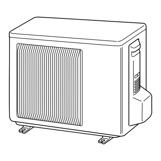
Page 7: Part Names And Functions
PART NAMES AND FUNCTIONS MUZ-GA25VA MUZ-GA35VA MUZ-GA25VAH MUZ-GA35VAH Air inlet (back and side) Piping Drain hose Air outlet Drain outlet ACCESSORIES MUZ-GA25VA - MUZ-GA25VAH - MUZ-GA25VA - MUZ-GA25VAH - MUZ-GA25VA - MUZ-GA25VAH - MUZ-GA35VA - MUZ-GA35VAH - MUZ-GA25VA - MUZ-GA25VAH - MUZ-GA35VA -... -
Page 8: Specification
SPECIFICATION MUZ-GA25VA MUZ-GA35VA Outdoor model MUZ-GA25VAH MUZ-GA35VAH Cooling Function Heating Cooling Heating Single phase Single phase Power supply 230V,50Hz 230V,50Hz 3.5 (1.0-3.9) 4.0 (0.9-5.0) 2.5 (0.9-3.0) 3.2 (0.9-4.5) Capacity Rated frequency(Min.-Max.) — — Dehumidification 2,178 1,890 2,058 K /h Air flow 1 Power outlet 2.95... - Page 9 — (SR61) FQ-208-RK (for Solenoid valve coil (21R1) — Heater protector Open 45: — (26H) Open 45: — Open 152: Outdoor fan motor thermal fuse — w1 Refer to Revision A. w2 MUZ-GA25VA- (Serial No. ~6021350T) MUZ-GA25VAH- (Serial No. ~7000000T)
-
Page 10: Noise Criteria Curves
NOISE CRITERIA CURVES MUZ-GA25VA MUZ-GA35VA MUZ-GA25VAH MUZ-GA35VAH FUNCTION SPL(dB(A)) LINE FAN SPEED FUNCTION SPL(dB(A)) LINE COOLING COOLING High Med. HEATING HEATING Test conditions Test conditions Cooling : Dry-bulb temperature 35: Wet-bulb temperature (24:) Cooling : Dry-bulb temperature 35: Wet-bulb temperature (24:) -
Page 11: Outlines And Dimensions
OUTLINES AND DIMENSIONS MUZ-GA25VA MUZ-GA35VA Unit: mm MUZ-GA25VAH MUZ-GA35VAH REQUIRED SPACE Basically open 100mm or more without any obstruction in front and on both sides of the unit. Drain hole [42 (MUZ-GA25/GA35VA) Drain hole [33 (MUZ-GA25/GA35VAH) Air in Air in Open two sides of left, right, or rear side. -
Page 12: Wiring Diagram
WIRING DIAGRAM MUZ-GA25VA- MUZ-GA25VA- MUZ-GA25VA- (Serial No. ~6021350T) - Page 13 MUZ-GA25VA- (Serial No. 6021351T~) MUZ-GA25VA-...
- Page 14 MUZ-GA25VAH- MUZ-GA25VAH- (Serial No. ~7000000T) MUZ-GA25VAH-...
- Page 15 MUZ-GA25VAH- (Serial No. 7000001T~) MUZ-GA25VAH-...
- Page 16 MUZ-GA35VA...
- Page 17 MUZ-GA35VAH...
- Page 18 MUZ-GA35VA w w Alternative inverter P.C. board...
- Page 19 MUZ-GA35VAH w w Alternative inverter P.C. board...
-
Page 20: Refrigerant System Diagram
REFRIGERANT SYSTEM DIAGRAM MUZ-GA25VA - MUZ-GA25VA - Unit:mm MUZ-GA25VAH - MUZ-GA25VAH - 4-way valve Refrigerant pipe [9.52 (with heat insulator) Muffler Stop valve (with service port) Outdoor Muffler Discharge heat Flared connection exchanger temperature thermistor RT62 Ambient Compressor temperature thermistor... - Page 21 MUZ-GA25VA - Unit:mm MUZ-GA25VAH - 4-way valve Refrigerant pipe [9.52 (with heat insulator) Muffler Stop valve (with service port) Outdoor Muffler Discharge heat Flared connection exchanger temperature thermistor RT62 Ambient Compressor temperature thermistor Defrost RT65 thermistor RT61 Strainer Capillary tube #100 [3.0 [1.4 400...
- Page 22 MAX. REFRIGERANT PIPING LENGTH and MAX. HEIGHT DIFFERENCE Refrigerant piping : m Piping size O.D : mm Model Max. length Max. Height difference Liquid MUZ-GA25VA MUZ-GA25VAH 6.35 9.52 MUZ-GA35VA MUZ-GA35VAH Indoor unit Max. Height difference Max. length Outdoor unit ADDITIONAL REFRIGERANT CHARGE (R410A:g)
-
Page 23: Performance Curves
PERFORMANCE CURVES MUZ-GA25VA MUZ-GA35VA MUZ-GA25VAH MUZ-GA35VAH The standard data contained in these specifications apply only to the operation of the air conditioner under normal conditions. Since operating conditions vary according to the areas where these units are installed, the following information has been pro- vided to clarify the operating characteristics of the air conditioner under the conditions indicated by the performance curve. - Page 24 Outdoor intake air Wet-bulb temperature (:) Outdoor intake air Wet-bulb temperature (:) NOTE:The above broken lines are for the heating operation without any frost and defrost operation. 8-2. Capacity and input correction by operational frequency of compressor MUZ-GA25VA MUZ-GA25VA MUZ-GA25VA MUZ-GA25VA MUZ-GA25VAH...
-
Page 25: Cool Operation
COOL operation Relative humidity(%) Dry-bulb temperature(:) 1 Both indoor and outdoor unit are under the same temperature/humidity condition. 2 Operation : TEST RUN OPERATION (refer to 8-3.) MUZ-GA35VA MUZ-GA25VA MUZ-GA35VAH MUZ-GA25VAH (kgf/F [Gauge]) (MPa [Gauge]) (kgf/F [Gauge]) (MPa [Gauge]) 88Hz 65Hz 35(˚C) - Page 26 PERFORMANCE DATA COOL operation Rated frequency 65Hz MUZ-GA25VA MUZ-GA25VAH CAPACITY:2.5(kW) SHF:0.79 INPUT:640(W) OUTDOOR DB( : ) INDOOR INDOOR WB(:) DB(:) SHC SHF INPUT SHC SHF INPUT SHC SHF INPUT SHC SHF INPUT 2.94 1.79 0.61 2.81 1.72 0.61 2.70 1.65 0.61 2.60 1.59 0.61...
- Page 27 PERFORMANCE DATA COOL operation Rated frequency 65Hz MUZ-GA25VA MUZ-GA25VAH CAPACITY:2.5(kW) SHF:0.79 INPUT:640(W) OUTDOOR DB( : ) INDOOR INDOOR DB (:) WB (:) SHC SHF INPUT SHC SHF INPUT SHC SHF INPUT 2.45 1.49 0.61 2.25 1.37 0.61 2.08 1.27 0.61 2.58 1.26 0.49...
- Page 28 PERFORMANCE DATA COOL operation Rated frequency 88Hz MUZ-GA35VA MUZ-GA35VAH CAPACITY:3.5(kW) SHF:0.76 INPUT:1080(W) OUTDOOR DB( : ) INDOOR INDOOR WB(:) DB(:) SHC SHF INPUT SHC SHF INPUT SHC SHF INPUT SHC SHF INPUT 4.11 2.39 0.58 3.94 2.28 0.58 3.78 2.19 0.58 3.64 2.11 0.58 4.29 1.97 0.46 4.11 1.89 0.46...
- Page 29 PERFORMANCE DATA COOL operation Rated frequency 88Hz MUZ-GA35VA MUZ-GA35VAH CAPACITY:3.5(kW) SHF:0.76 INPUT:1080(W) OUTDOOR DB( : ) INDOOR INDOOR DB (:) WB (:) SHC SHF INPUT SHC SHF INPUT SHC SHF INPUT 3.43 1.99 0.58 1058 3.15 1.83 0.58 1123 2.91 1.68 0.58 1166 3.61 1.66 0.46 1102...
- Page 30 PERFORMANCE DATA HEAT operation MUZ-GA25VA MUZ-GA25VAH Rated frequency 85Hz CAPACITY:3.2(kW) INPUT:760(W) OUTDOOR WB( : ) INDOOR DB( : ) INPUT INPUT INPUT INPUT INPUT INPUT INPUT 2.02 2.43 2.85 3.26 3.68 4.06 4.48 1.92 2.30 2.72 3.10 3.52 3.90 4.30 1.73...
-
Page 31: Actuator Control
ACTUATOR CONTROL MUZ-GA25VA MUZ-GA35VA MUZ-GA25VAH MUZ-GA35VAH 9-1. Outdoor fan motor control The fan motor turns ON/OFF, interlocking with the compressor. [ON] The fan motor turns ON 5 seconds before the compressor starts up. [OFF] The fan motor turns OFF 15 seconds after the compressor has stopped running. -
Page 32: Service Functions
SERVICE FUNCTIONS MUZ-GA25VA MUZ-GA35VA MUZ-GA25VAH MUZ-GA35VAH CHANGE IN DEFROST SETTING <JS> When the JS wire of the outdoor Inverter P.C. board is cut/ soldered, the defrost finish temperature is changed. (Refer to 11-7-1.) Defrost finish temperature Jumper wire MUZ-GA25VA MUZ-GA25VAH... - Page 33 11-2. Failure mode recall function Outline of the function This air conditioner can memorize the abnormal condition which has occurred once. Even though LED indication listed on the troubleshooting check table (11-4.) disappears, the memorized failure details can be recalled. This mode is very useful when the unit needs to be repaired for the abnormality which doesn't recur.
- Page 34 2. Flow chart of the detailed outdoor unit failure mode recall function Operational procedure The outdoor unit might be abnormal. Confirm if outdoor unit is abnormal according to the following procedures. Confirm that the remote controller is in the failure mode recall function.
- Page 35 3. Outdoor unit failure mode table NOTE : Blinking patterns of this mode differ from the ones of Troubleshooting check table (11-4.).
- Page 36 11-3. Instruction of troubleshooting If blinking of OPERATION INDICATOR lamp cannot be checked, it can be checked Start with failure mode recall function. OPERATION Indoor unit Indoor unit INDICATOR Indoor unit operates. operates. doesn't receive lamp on the indoor Outdoor unit doesn't Outdoor unit the signal from unit is flashing on...
- Page 37 · Refer to 11-6.A "How to check 2.5 seconds OFF inverter/compressor". Frequency drop by The unit is normal, but check the 1-time flash When current from power outlet exceeds 5.2A(MUZ-GA25VA, Outdoor unit 2.5 seconds OFF current protection following. MUZ-GA25VAH)/ 6.1A(MUZ-GA35VA,MUZ-GA35VAH), operates compressor frequency lowers.
- Page 38 Outdoor fan motor(MF) RED BLK Color of the lead wire MUZ-GA25VA MUZ-GA35VA INNER FUSE MUZ-GA25VAH MUZ-GA35VAH (Only MUZ-GA25VA/H) FUSE 292 " ~ 374 " 31 " ~ 41 " WHT – BLK : CUT OFF 152i 236 " ~ 304 "...
-
Page 39: Troubleshooting Flow
11-6. Troubleshooting flow When OPERATION INDICATOR lamp flashes 5-time. Outdoor unit does not operate. How to check inverter/ compressor Disconnect the connector (CN61) between compressor and the intelligent power module (IPM). Check the voltage See 11-6.B “Check of open phase” . between terminals. - Page 40 Check of compressor Refer to 11-6.E "Check of compressor winding". Replace the compressor. Is the compressor normal? Refer to 11-6.F "Check of Is the compressor compressor operation time". operation time more than Replace the compressor. Does the compressor 10 seconds? operate continuously? Check the refrigerant circuit.
- Page 41 When OPERATION INDICATOR lamp flashes 6-time. The thermistors in the outdoor unit are abnormal. Check of outdoor thermistors Disconnect the connectors CN641, CN642 and CN643 from the inverter P.C. board. Defrost thermistor RT61 (Check the characteristics of each thermistor.) Measure the resistance between CN641 1 and 2.
- Page 42 Outdoor fan motor does not operate. Check of outdoor fan motor MUZ-GA25VA MUZ-GA25VAH Check the resistance of fan motor. (Refer to 11-5.) Replace the outdoor Is the resistance of fan fan motor. motor normal? Disconnect the connector CN771 on the power P.C.
- Page 43 Outdoor fan motor does not operate. Check of outdoor fan motor MUZ-GA35VA MUZ-GA35VAH Rotate the outdoor fan slowly by hand, and measure the Is the resistance Disconnect CN932 voltage of CN931 (Measurement between each terminal of Turn ON the from the inverter of feedback output).
- Page 44 Outdoor unit does not operate at all, or stops immediately due to overcurrent. Check of current-limiting resistor When the current-limiting resistor is open, the rush current limiting relay (X64) may not work properly. Is the resistance of current-limiting Turn ON the power Replace the power P.C.
- Page 45 Outdoor base gets frozen. Check of defrost heater <MUZ-GA25VAH MUZ-GA35VAH> Check the following points before checking electric continuity. 1) Does the resistance of ambient temperature thermistor have the characteristics? Refer to 11-7.1. 2) Is the resistance of defrost heater normal? Refer to 11-5. 3) Does the heater protector remain conducted (not open)? 4) Are both ambient temperature thermistor and circuit of defrost heater securely connected to connectors? In HEAT mode, for more than 5 minutes, let the ambient temperature thermistor continue to read 5: or less, and let the...
- Page 46 Outdoor fan motor does not operate, or stops immediately after starting up. Check of inverter P.C. board MUZ-GA35VA MUZ-GA35VAH w w Alternative inverter P.C. board Check the outdoor fan motor. (Refer to11-6.I.) Is the fuse (F901) blown on the inverter P.C. board? Inverter P.C.board Check the connection of the connectors.
- Page 47 • When unit cannot operate neither by the remote controller nor by EMERGENCY OPERATION switch. Indoor unit does not operate. • When OPERATION INDICATOR lamp flashes ON and OFF in every 0.5-second. Outdoor unit doesn’t operate. How to check mis-wiring and serial signal error (when outdoor unit does not work) Turn OFF the power supply.
- Page 48 When the cool air does not blow out from the indoor unit in Low Outside Temperature Operation, or the condensed water drops from the indoor unit. Operation check of the solenoid valve. MUZ-GA25VA- (Serial No. ~6021350T) MUZ-GA25VAH- (Serial No. ~7000000T) Set the failure mode recall function.(Refer to 11-2.)
- Page 49 Electromagnetic noise enters into TV sets or radios Is the unit earthed? Earth the unit. Is the distance between the Extend the distance between antennas and the indoor the antennas and the indoor unit within 3m, or is the unit, and/or the antennas and distance between the the outdoor unit.
- Page 50 11-7. Test point diagram and voltage. MUZ-GA25VA MUZ-GA35VA MUZ-GA25VAH MUZ-GA35VAH 1. Inverter P.C. board Output to drive Smoothing capacitor Smoothing capacitor FUSE Smoothing capacitor Back side of unit compressor (C63A) (F801) (C63B) (C63C) (LDV,LDW,LDU) DB61 1(+) 280V ~ 370V 2(+)
- Page 51 11-7. Test point diagram and voltage MUZ-GA25VA MUZ-GA35VA MUZ-GA25VAH MUZ-GA35VAH 1. Inverter P.C. board (Alternative) Back side of unit 230V AC Smoothing capacitor Smoothing capacitor Smoothing capacitor DB61 DB61 (C63C) (C63B) (C63A) 280V ~ 370V FUSE (F801) FUSE (F901) LED monitor...
- Page 52 MUZ-GA25VA MUZ-GA35VA MUZ-GA25VAH MUZ-GA35VAH 2. Power P.C. board MUZ-GA25VA- (Serial No. ~6021350T) MUZ-GA25VAH- (Serial No. ~7000000T) Solenoid valve coil Back side of unit Front side of unit Varistor Varistor Varistor (CN923) (NR63) (NR62) (NR64) 230V AC 230V AC MUZ-GA25VA MUZ-GA25VAH...
-
Page 53: Disassembly Instructions
1Hold the sleeve, and 2Pull the terminal while pull out the terminal pushing the locking slowly. Locking lever lever. Connector MUZ-GA25VA MUZ-GA35VA MUZ-GA25VAH MUZ-GA35VAH OPERATING PROCEDURE PHOTOS 1. Removing the cabinet Photo 1 (1) Remove the screw fixing the service panel. (See Photo 2.) Screws (2) Pull down the service panel and remove it. - Page 54 (3) Disconnect the ground wires (See Photo 3.), the lead wire to the reactor and the following connectors; <Power P.C. board> CN721 (4-way valve) CN771 (Fan motor) MUZ-GA25VA/GA25VAH CN722 (Defrost heater) MUZ-GA25/GA35VAH CN923 (Solenoid valve coil) MUZ-GA25VA- (Serial No. ~6021350T) MUZ-GA25VAH- (Serial No.
- Page 55 OPERATING PROCEDURE PHOTOS 5. Removing outdoor fan motor Photo 6 (1) Remove the top panel, cabinet and service panel. (Refer to 1.) (2) Disconnect the power supply and indoor/outdoor connecting wire and remove the back panel. (Refer to 1.) (3) Disconnect the connectors for outdoor fan motor. (4) Remove the propeller nut.
- Page 56 PARTS LIST (non-RoHS compliant) MUZ-GA25VA MUZ-GA35VA MUZ-GA25VAH MUZ-GA35VAH 13-1. OUTDOOR UNIT STRUCTURAL PARTS AND FUNCTIONAL PARTS 10 9...
-
Page 57: Parts List
PARTS LIST (non-RoHS compliant) MUZ-GA25VA MUZ-GA35VA MUZ-GA25VAH MUZ-GA35VAH 13-1. OUTDOOR UNIT STRUCTURAL PARTS AND FUNCTIONAL PARTS Part numbers that are circled are not shown in the illustration. Symbol Q'ty/unit MUZ- MUZ- MUZ- MUZ- in Wiring Part Name Remarks Part No. - Page 58 PARTS LIST (non-RoHS compliant) MUZ-GA25VA MUZ-GA35VA MUZ-GA25VAH MUZ-GA35VAH 13-2. OUTDOOR UNIT ELECTRICAL PARTS Part numbers that are circled are not shown in the illustration. Q'ty/unit Symbol MUZ- MUZ- MUZ- MUZ- in Wiring Part No. Part Name Remarks GA25VA- GA25VAH- GA35VA-...
- Page 59 PARTS LIST (non-RoHS compliant) MUZ-GA25VA MUZ-GA35VA 13-3. DRAIN SOCKET Q'ty/unit Symbol MUZ- MUZ- MUZ- MUZ- in Wiring Parts No. Parts Name Remarks GA25VA- GA25VA- GA35VA- GA35VA- Diagram E02 838 704 DRAIN SOCKET MUZ-GA25VA - MUZ-GA35VA - MUZ-GA25VAH - MUZ-GA35VAH - 13-4.
- Page 60 RoHS PARTS LIST (RoHS compliant) MUZ-GA25VA MUZ-GA35VA MUZ-GA25VAH MUZ-GA35VAH 14-1. OUTDOOR UNIT STRUCTURAL PARTS AND FUNCTIONAL PARTS 10 9...
-
Page 61: Rohs Parts List
RoHS PARTS LIST (RoHS compliant) MUZ-GA25VA MUZ-GA35VA MUZ-GA25VAH MUZ-GA35VAH 14-1. OUTDOOR UNIT STRUCTURAL PARTS AND FUNCTIONAL PARTS Part numbers that are circled are not shown in the illustration. Symbol Q'ty/unit MUZ- MUZ- MUZ- MUZ- in Wiring Part Name Remarks Part No. - Page 62 RoHS PARTS LIST (RoHS compliant) MUZ-GA25VA MUZ-GA35VA MUZ-GA25VAH MUZ-GA35VAH 14-2. OUTDOOR UNIT ELECTRICAL PARTS Part numbers that are circled are not shown in the illustration. Q'ty/unit Symbol MUZ- MUZ- MUZ- MUZ- in Wiring Remarks Part No. Part Name GA25VA- GA25VAH-...
- Page 63 RoHS PARTS LIST (RoHS compliant) MUZ-GA25VA MUZ-GA35VA 14-3. DRAIN SOCKET Q'ty/unit Symbol MUZ- in Wiring Parts No. Parts Name MUZ-GA25VA- Remarks GA35VA- Diagram E12 838 704 DRAIN SOCKET...
- Page 64 HEAD OFFICE: TOKYO BLDG., 2-7-3, MARUNOUCHI, CHIYODA-KU, TOKYO 100-8310, JAPAN C C Copyright 2005 MITSUBISHI ELECTRIC ENGINEERING CO.,LTD Distributed in Feb. 2007. No. OB379 REVISED EDITION-C 6 Distributed in May 2006. No. OB379 REVISED EDITION-B 6 Distributed in Jan. 2006. No. OB379 REVISED EDITION-A 6 New publication, effective Feb.