Mitsubishi Electric MUZ-GA50VA Service Manual
Split-type, heat pump air conditioners
Hide thumbs
Also See for MUZ-GA50VA:
- Service manual (56 pages) ,
- Operating instructions manual (13 pages)
Table of Contents
Advertisement
SPLIT-TYPE, HEAT PUMP AIR CONDITIONERS
SERVICE MANUAL
Wireless type
Models
MUZ-GA50VA -
MUZ-GA60VA -
MUZ-GA71VA -
NOTE:
This service manual describes technical data of the outdoor units.
•As for indoor units MSZ-GA50VA -
the service manual OB388.
E1
E1
E1
Indication of
model name
MUZ-GA50VA -
E1
MUZ-GA60VA -
E1
MUZ-GA71VA -
E1
, MSZ-GA60VA -
and MSZ-GA71VA -
E1
E1
HFC
utilized
R410A
CONTENTS
1. TECHNICAL CHANGES ····································2
2. PART NAMES AND FUNCTIONS······················5
3. SPECIFICATION·················································5
4. NOISE CRITERIA CURVES ·······························7
5. OUTLINES AND DIMENSIONS ·························8
6. WIRING DIAGRAM ············································9
7. REFRIGERANT SYSTEM DIAGRAM ··············11
8. PERFORMANCE CURVES ······························13
9. ACTUATOR CONTROL····································24
10. TROUBLESHOOTING······································25
11. DISASSEMBLY INSTRUCTIONS·····················44
12. PARTS LIST······················································48
, refer to
E1
No. OB389
Advertisement
Table of Contents
Troubleshooting

Related Manuals for Mitsubishi Electric MUZ-GA50VA


Summary of Contents for Mitsubishi Electric MUZ-GA50VA
-
Page 1: Table Of Contents
SPLIT-TYPE, HEAT PUMP AIR CONDITIONERS utilized SERVICE MANUAL R410A No. OB389 Wireless type Models MUZ-GA50VA - MUZ-GA60VA - MUZ-GA71VA - CONTENTS 1. TECHNICAL CHANGES ····································2 2. PART NAMES AND FUNCTIONS······················5 3. SPECIFICATION·················································5 Indication of 4. NOISE CRITERIA CURVES ·······························7 model name MUZ-GA50VA - 5. -
Page 2: Technical Changes
TECHNICAL CHANGES MUZ-A18YV - MUZ-GA50VA - MUZ-A24YV - MUZ-GA60VA - MUZ-A26YV - MUZ-GA71VA - 1.Indication of capacity has been changed.(BTU base kW base) 2.Outdoor electronic control P.C. board has been changed. 3.Noise filter P.C. board has been changed. 4.Length of fan motor lead wire been changed. - Page 3 Conversion chart of refrigerant temperature and pressure (MPa [Gauge]) R410A NOTE : The unit of pressure has been changed to MPa on the international system of units(SI unit system). The conversion factor is: 1(MPa [Gauge]) =10.2(kgf/f f [Gauge]) -0.5 -30 -20 -10 1.Tools dedicated for the air conditioner with R410A refrigerant The following tools are required for R410A refrigerant.
- Page 4 2 Flaring work and flare nut Flaring work for R410A pipe differs from that for R22 pipe. For details of flaring work, refer to Installation manual “FLARING WORK”. Dimension of flare nut Pipe diameter R410A 6.35 9.52 12.7 15.88 3.Refrigerant oil Apply the special refrigeration oil (accessories: packed with indoor unit) to the flare and the union seat surfaces.
-
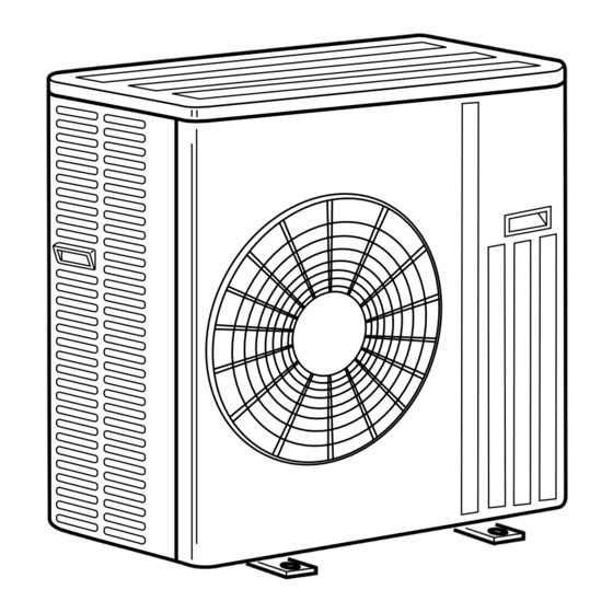
Page 5: Part Names And Functions
PART NAMES AND FUNCTIONS MUZ-GA50VA - ACCESSORIES MUZ-GA60VA - MUZ-GA71VA - OUTDOOR UNIT Air inlet (back and side) MUZ-GA50VA - MUZ-GA60VA - Piping MUZ-GA71VA - Drain hose Drain socket Drain cap [33 Air outlet Drain outlet SPECIFICATION MUZ-GA71VA - Outdoor model... -
Page 6: Outdoor Unit
Specifications and rating conditions of main electric parts OUTDOOR UNIT Model MUZ-GA50VA - MUZ-GA60VA - MUZ-GA71VA - Item (CB1,2,3) Smoothing capacitor 560+ 450V (CT1,2) ETQ19Z68AY Current transformer (CT61) Current transformer ETQ19Z53AY (F64) Fuse 250V 2A (F801) Fuse 250V 3.15A (F911) -
Page 7: Noise Criteria Curves
NOISE CRITERIA CURVES MUZ-GA50VA - MUZ-GA60VA - MUZ-GA71VA - FAN SPEED FUNCTION SPL(dB(A)) LINE COOLING High HEATING Test conditions, Cooling : Dry-bulb temperature 35: Wet-bulb temperature (24:) Heating : Dry-bulb temperature 7: Wet-bulb temperature 6: OUTDOOR UNIT NC-70 NC-60 MICROPHONE... -
Page 8: Outlines And Dimensions
Open as a rule 500mm or more if the back, 350mm or more both sides and top are open Service panel Liquid refrigerant pipe joint Refrigerant pipe (flared) [6.35 (MUZ-GA50/GA60VA) [9.52 (MUZ-GA71VA) Gas refrigerant pipe joint Refrigerant pipe (flared) [12.7 (MUZ-GA50VA) [15.88 (MUZ-GA60/GA71VA) -
Page 9: Wiring Diagram
WIRING DIAGRAM MUZ-GA50VA - MUZ-GA60VA - MODELS WIRING DIAGRAM OUTDOOR UNIT... - Page 10 MUZ-GA71VA - MODEL WIRING DIAGRAM OUTDOOR UNIT...
-
Page 11: Refrigerant System Diagram
REFRIGERANT SYSTEM DIAGRAM MUZ-GA50VA - Unit:mm MUZ-GA60VA - OUTDOOR UNIT Refrigerant pipe [12.7 (MUZ-GA50VA) Muffler #100 (with heat insulator) [15.88 (MUZ-GA60VA) 4-way valve Stop valve (with service port) Outdoor Flared connection Discharge heat Ambient temperature exchanger temperature thermistor Defrost thermistor... - Page 12 MAX. REFRIGERANT PIPING LENGTH Refrigerant piping Piping size O.D : mm Length of connecting pipe : m Model Max. length : m Liquid Indoor unit Outdoor unit MUZ-GA50VA - 12.7 6.35 Gas 0.43 Gas 0 MUZ-GA60VA - Liquid 0.5 Liquid 0 15.88 MUZ-GA71VA - 9.52...
-
Page 13: Performance Curves
PERFORMANCE CURVES MUZ-GA50VA - MUZ-GA60VA - MUZ-GA71VA - The standard data contained in these specifications apply only to the operation of the air conditioner under normal conditions. Since operating conditions vary according to the areas where these units are installed. The following information has been provided to clarify the operating characteristics of the air conditioner under the conditions indicated by the performance curve. - Page 14 10.8 12.9 Outdoor intake air Wet-bulb temperature (:) Outdoor intake air Wet-bulb temperature (:) NOTE:The above curves are for the heating operation without any frost. MUZ-GA50VA - MUZ-GA50VA - MUZ-GA50VA - MUZ-GA50VA - Correction of Cooling capacity Correction of Cooling total input...
- Page 15 OUTDOOR LOW PRESSURE AND OUTDOOR UNIT CURRENT COOL operation 1 Both indoor and outdoor unit are under the Dry-bulb temperature Relative humidity(%) same temperature/humidity condition. 2 Air flow : High speed 3 Operational frequency : 71Hz(MUZ-GA50VA) 87Hz(MUZ-GA60VA) 62Hz(MUZ-GA71VA) MUZ-GA50VA - MUZ-GA50VA - (kgf/F [Gauge]) (MPa [Gauge])
-
Page 16: Heat Operation
HEAT operation Condition indoor: Dry bulb temperature 20.0°C Operational frequency : 58Hz Wet bulb temperature 14.5°C Condition outdoor: Dry bulb temperature 2,7,15,20.0°C Wet bulb temperature 1,6,12,14.5°C MUZ-GA50VA - 10.0 58Hz 25(:) Ambient temperature(˚C) MUZ-GA60VA - MUZ-GA71VA - 16.0 12.0 58Hz 15.0... - Page 17 PERFORMANCE DATA COOL operation Rated frequency 71Hz MSZ-GA50VA - : MUZ-GA50VA - CAPACITY:5.0(kW) SHF:0.73 INPUT:1460(W) OUTDOOR DB( : ) INDOOR INDOOR WB(:) DB(:) SHC SHF INPUT SHC SHF INPUT SHC SHF INPUT SHC SHF INPUT 5.88 3.23 0.55 1168 5.63 3.09 0.55 1226 5.40 2.97 0.55...
- Page 18 PERFORMANCE DATA COOL operation Rated frequency 71Hz MSZ-GA50VA - : MUZ-GA50VA - CAPACITY:5.0(kW) SHF:0.73 INPUT:1460(W) OUTDOOR DB( : ) INDOOR INDOOR DB (:) WB (:) SHC SHF INPUT SHC SHF INPUT SHC SHF INPUT 4.90 2.70 0.55 1431 4.50 2.48 0.55 1518 4.33 2.38 0.55...
- Page 19 PERFORMANCE DATA COOL operation Rated frequency 87Hz MSZ-GA60VA - : MUZ-GA60VA - CAPACITY:6.0(kW) SHF:0.79 INPUT:1930(W) OUTDOOR DB( : ) INDOOR INDOOR WB(:) DB(:) SHC SHF INPUT SHC SHF INPUT SHC SHF INPUT SHC SHF INPUT 7.05 4.30 0.61 1544 6.75 4.12 0.61 1621 6.48 3.95 0.61 1698...
- Page 20 PERFORMANCE DATA COOL operation Rated frequency 87Hz MSZ-GA60VA - : MUZ-G60VA - CAPACITY:6.0(kW) SHF:0.79 INPUT:1930(W) OUTDOOR DB( : ) INDOOR INDOOR DB (:) WB (:) SHC SHF INPUT SHC SHF INPUT SHC SHF INPUT 5.88 3.59 0.61 1891 5.40 3.29 0.61 2007 5.19 3.17 0.61 2046...
- Page 21 PERFORMANCE DATA COOL operation Rated frequency 62Hz MSZ-GA71VA - : MUZ-GA71VA - CAPACITY:7.1(kW) SHF:0.71 INPUT:2420(W) OUTDOOR DB( : ) INDOOR INDOOR WB(:) DB(:) SHC SHF INPUT SHC SHF INPUT SHC SHF INPUT SHC SHF INPUT 8.34 4.42 0.53 1936 7.99 4.23 0.53 2033 7.67 4.06 0.53 2130...
- Page 22 PERFORMANCE DATA COOL operation Rated frequency 62Hz MSZ-GA71VA - : MUZ-GA71VA - CAPACITY:7.1(kW) SHF:0.71 INPUT:2420(W) OUTDOOR DB( : ) INDOOR INDOOR DB (:) WB (:) SHC SHF INPUT SHC SHF INPUT SHC SHF INPUT 6.96 3.69 0.53 2372 6.39 3.39 0.53 2517 6.14 3.25 0.53 2565...
- Page 23 PERFORMANCE DATA HEAT operation MSZ-GA50VA - : MUZ-GA50VA - Rated frequency 81Hz CAPACITY:5.9(kW) INPUT:1630(W) OUTDOOR WB( : ) INDOOR DB( : ) INPUT INPUT INPUT INPUT INPUT INPUT INPUT 3.72 1060 4.48 1271 5.25 1434 6.02 1549 6.79 1646 7.49 1695 8.26...
-
Page 24: Actuator Control
ACTUATOR CONTROL MUZ-GA50VA - MUZ-GA60VA - MUZ-GA71VA - 9-1. Outdoor fan motor control The fan motor turns ON/OFF, interlocking with the compressor. [ON] The fan motor turns ON 5 seconds before the compressor starts up. [OFF] The fan motor turns OFF 15 seconds after the compressor has stopped running. -
Page 25: Troubleshooting
TROUBLESHOOTING MUZ-GA50VA - MUZ-GA60VA - MUZ-GA71VA - 10-1. Cautions on troubleshooting 1. Before troubleshooting, check the following: 1) Check the power supply voltage. 2) Check the indoor/outdoor connecting wire for mis-wiring. 2. Take care the following during servicing. 1) Before servicing the air conditioner, be sure to turn OFF the unit first with the remote controller, and then after confirming the horizontal vane is closed, turn off the breaker and / or disconnect the power plug. -
Page 26: Failure Mode Recall Function
10-2. Failure mode recall function Outline of the function This air conditioner can memorize the abnormal condition which has occurred once. Even though LED indication listed on the troubleshooting check table (10-4.) disappears, the memorized failure details can be recalled. This mode is very useful when the unit needs to be repaired for the abnormality which doesn't recur. - Page 27 2. Flow chart of the detailed outdoor unit failure mode recall function Operational procedure There is a possibility that the outdoor unit is abnormal. Confirm the presence of abnormality according to the following procedures. Confirm that the remote controller is in the failure mode recall function.
- Page 28 3. Failure mode table With outdoor failure mode recall function, you can check the following failures. With indoor/outdoor failure mode recall function, however, you can check the failures marked with " " only. Indoor/outdoor Abnormal point Outdoor LED indication Indoor operation failure mode Details of abnormal point Detecting method...
- Page 29 Indoor/outdoor Indoor operation Abnormal point Outdoor LED indication failure mode Details of abnormal point Detecting method Check point indicator lamp (Failure mode) LED1 LED2 recall function Normal 11-time flash Converter • Check the connecting wire Communication error Lighting 6 times When the communication between between P.C.
- Page 30 10-3. Instruction of troubleshooting Start Indoor unit Indoor unit OPERATION INDICATOR Indoor unit operates. operates. doesn't receive lamp on the indoor unit is Outdoor unit doesn't Outdoor unit the signal from flashing on and off. operate normally. doesn't remote controller. operate.
-
Page 31: Troubleshooting Check Table
10-4. Troubleshooting check table Outdoor electronic control P.C. board(Parts side) LED2 LED1 NOTE 1. The location of LED is illustrated at the right figure. Lighting 2. LED lights up during normal operation. Symptom: Outdoor unit does not operate. Indication Abnormal point Detecting method Check points LED1(Red) LED2(Yellow) - Page 32 Symptom: Outdoor unit does not operate normally. Indication Abnormal point Detecting method Check points LED1 LED2 When the input current exceeds 15A. These symptoms do not mean any abnormality of the Primary current protection Once Lighting product, but check the following points. Secondary current protection When the current of the compressor exceeds 15A.
- Page 33 10-5. Trouble criterion of main parts MUZ-GA50VA - MUZ-GA60VA - MUZ-GA71VA - Part name Check method and criterion Defrost thermistor/ Measure the resistance using a tester. Ambient temperature (Part temperature : -10°C ~ 40°C) thermistor/ Outdoor heat Normal abnormal exchanger temperature Open or short-circuit 5kΩ...
- Page 34 10-6. Troubleshooting flow Outdoor unit does not operate. (LED display: display OFF) A A Check of power supply Start Check the connecting of parts of main power supply circuit. Turn on power supply. Is there voltage of 230V AC in the Check the power supply cable.
- Page 35 • When unit cannot operate neither by the remote controller nor by EMERGENCY OPERATION switch. Indoor unit does not operate. • When OPERATION INDICATOR lamp flashes ON and OFF in every 0.5-second. Outdoor unit does not operate. B B How to check mis-wiring and serial signal error (when outdoor unit does not work) Turn OFF the power supply.
- Page 36 The cooling operation or heating operation does not operate. (LED display: Both LED1 and LED2 lighting) C C Check of R.V. coil • When heating operation does not work. Start 1. Disconnect the lead wire leading to the compressor. 2. 3 minutes after turning on the power supply, start EMERGENCY OPERATION in HEAT mode.
- Page 37 • When cooling, heat exchanger of non-operating indoor unit frosts. • When heating, non-operating indoor unit get warm. D D Check of LEV LED display: LED1 LED2 Lighting Lighting 6 time Goes out Start Turn on power supply to the outdoor unit after checking LEV coil is mounted to the LEV body securely.
- Page 38 • When OPERATION INDICATOR lamp flashes 6-time. • When thermistor is abnormal. (When the LED display is a table below.) F F Check of outdoor thermistors Start Disconnect the connector in the outdoor electronic control P.C. board or the outdoor power board Replace the thermistor.
- Page 39 • When the operation frequency does not go up from lowest frequency. H H Check of HPS MUZ-GA71VA Start 1. Disconnect the connector CN681 in the electronic control P.C. board. 2. Check the resistance of HPS after 1 minutes have passed since the outdoor unit power supply was turned off. Infinity Check the resistance between Replace HPS.
-
Page 40: Electromagnetic Noise Enters Into Tv Sets Or Radios
Electromagnetic noise enters into TV sets or radios Is the unit earthed? Earth the unit. Is the distance between the Extend the distance between antennas and the indoor the antennas and the indoor unit within 3m, or is the unit, or the antennas and the distance between the outdoor unit. - Page 41 10-7. Test point diagram and voltage 1. Outdoor electronic control P.C. board Defrost thermistor (RT61) MUZ-GA50VA - MUZ-GA60VA - MUZ-GA71VA - Ambient temperature thermistor (RT65) Outdoor heat exchanger temperature thermistor (RT68) Fin temperature thermistor (RT64) Discharge temperature thermistor (RT62) 10 20 30 40 50 60 70 80 100 110 120 Temperature (;)
- Page 42 2. Noise filter P.C. board MUZ-GA50VA - MUZ-GA60VA - MUZ-GA71VA - CN901 To electronic CN902 CN903 control To power To power P.C. board board board 230V AC 50Hz Input CN912 R.V. coil 230V AC 230V AC 230V AC 50Hz 50Hz Output...
- Page 43 3. Outdoor power board MUZ-GA50VA - MUZ-GA60VA - MUZ-GA71VA - Connect to the compressor Voltage among phases: 5V to 180V 325-370V DC Output (Red) (–) (White) Connect to the earth Signal reception (From electronic control P.C. board) 5V DC pulse wave...
-
Page 44: Disassembly Instructions
Locking lever lever. Connector NOTE : These photos are MUZ-GA71VA. MUZ-GA50VA - MUZ-GA60VA - MUZ-GA71VA - Other models are almost the same as OUTDOOR UNIT MUZ-GA71VA. OPERATING PROCEDURE PHOTOS 1. Removing the cabinet... - Page 45 OPERATING PROCEDURE PHOTOS 2. Removing the inverter assembly, inverter P.C. board Photo 4 and power board Screws of the power board assembly (1) Remove the top panel, cabinet and service panel. (Refer to 1.) (2) Remove the back panel.(Refer to 1.) (3) Disconnect the following connectors;...
- Page 46 OPERATING PROCEDURE PHOTOS 4. Removing the defrost thermistor, discharge temper- Photo 5 ature thermistor, outdoor heat exchanger tempera- Discharge temperature thermistor ture thermistor and ambient temperature thermistor (1) Remove the top panel, cabinet and service panel. (Refer to 1.) (2) Remove the back panel. (Refer to 1.) (3) Remove the inverter assembly.
- Page 47 OPERATING PROCEDURE PHOTOS 6. Removing the compressor and 4-way valve Photo 8 (1) Remove the top panel, cabinet and service panel. (Refer to 1.) (2) Remove the back panel. (Refer to 1.) (3) Remove the inverter assembly. (Refer to 2.) (4) Recover gas from the refrigerant circuit.
-
Page 48: Parts List
PARTS LIST MUZ-GA50VA - MUZ-GA60VA - MUZ-GA71VA - 12-1. OUTDOOR UNIT STRUCTURAL PARTS, ELECTRICAL PARTS AND FUNCTIONAL PARTS These figures show about MUZ-A26YV. - Page 49 MUZ-GA50VA - MUZ-GA60VA - MUZ-GA71VA - 12-1. OUTDOOR UNIT STRUCTURAL PARTS, ELECTRICAL PARTS AND FUNCTIONAL PARTS Part numbers that are circled are not shown in the illustration. Q'ty/unit Symbol Part No. Part Name in Wiring Remarks MUZ-GA50 MUZ-GA60 MUZ-GA71 Diagram...
- Page 50 MUZ-GA50VA - MUZ-GA60VA - MUZ-GA71VA - 12-2. ACCESSORY Q'ty/unit Symbol in Wiring Remarks Part No. Part Name MUZ-GA50 MUZ-GA60 MUZ-GA71 Diagram VA - VA - VA - E02 817 704 DRAIN SOCKET E02 444 705 DRAIN CAP...
- Page 52 HEAD OFFICE: MITSUBISHI DENKI BLDG., 2-2-3, MARUNOUCHI, CHIYODA-KU, TOKYO100-8310, JAPAN C C Copyright 2005 MITSUBISHI ELECTRIC ENGINEERING CO.,LTD Distributed in Jan. 2005. No. OB389 6 New publication, effective Jan. 2005 Made in Japan Specifications subject to change without notice.