Table of Contents
Advertisement
Quick Links
RETURN TO MAIN INDEX
SVM123-A
TM
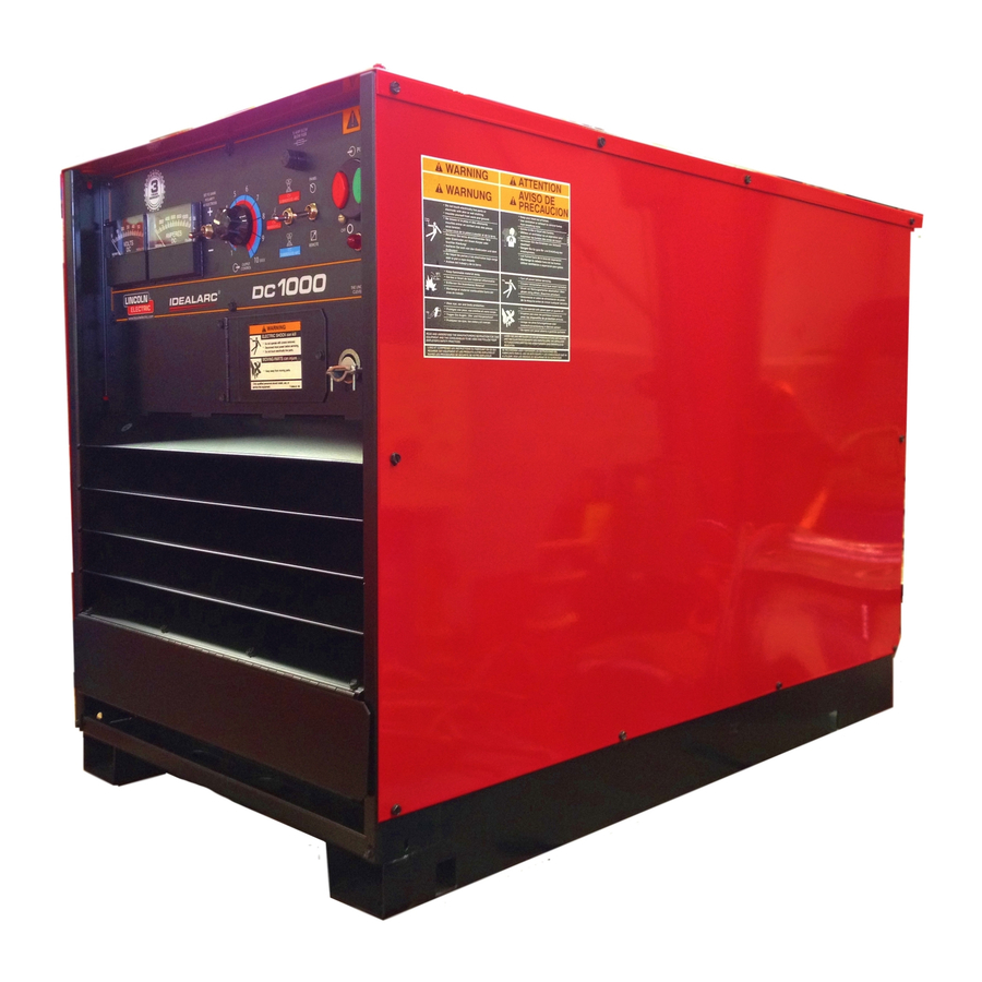
IDEALARC DC 1000
July, 1996
For use with Machine Code Numbers: 9919
9920
Safety Depends on You
Lincoln arc welding and cutting
equipment is designed and built
with safety in mind. However,
your overall safety can be
increased by proper installation
... and thoughtful operation on
your part. DO NOT INSTALL,
OPERATE OR REPAIR THIS
EQUIPMENT WITHOUT READ-
ING THIS MANUAL AND THE
SAFETY PRECAUTIONS CON-
TAINED THROUGHOUT. And,
most importantly, think before
you act and be careful.
SERVICE MANUAL
World's Leader in Welding and Cutting Products
Premier Manufacturer of Industrial Motors
Sales and Service through Subsidiaries and Distributors Worldwide
22801 St. Clair Ave. Cleveland, Ohio 44117-1199 U.S.A. Tel. (216) 481-8100
Advertisement
Chapters
Table of Contents
Troubleshooting

Related Manuals for Lincoln Electric IDEALARC DC 1000 SVM123-A


Summary of Contents for Lincoln Electric IDEALARC DC 1000 SVM123-A
- Page 1 RETURN TO MAIN INDEX SVM123-A IDEALARC DC 1000 July, 1996 For use with Machine Code Numbers: 9919 9920 Safety Depends on You Lincoln arc welding and cutting equipment is designed and built with safety in mind. However, your overall safety can be increased by proper installation ...
-
Page 2: Safety
351040, Miami, Florida 33135 or CSA Standard W117.2-1974. A Free copy of “Arc Welding Safety” booklet E205 is available from the Lincoln Electric Company, 22801 St. Clair Avenue, Cleveland, Ohio 44117-1199. BE SURE THAT ALL INSTALLATION, OPERATION, MAINTENANCE AND REPAIR PROCEDURES ARE PERFORMED ONLY BY QUALIFIED INDIVIDUALS. -
Page 3: Electric Shock Can Kill
ELECTRIC SHOCK can kill. 3.a. The electrode and work (or ground) circuits are electrically “hot” when the welder is on. Do not touch these “hot” parts with your bare skin or wet clothing. Wear dry, hole-free gloves to insulate hands. 3.b. - Page 4 WELDING SPARKS can cause fire or explosion. 6.a. Remove fire hazards from the welding area. If this is not possible, cover them to prevent the welding sparks from starting a fire. Remember that welding sparks and hot materials from welding can easily go through small cracks and openings to adjacent areas.
- Page 5 PRÉCAUTIONS DE SÛRETÉ Pour votre propre protection lire et observer toutes les instruc- tions et les précautions de sûreté specifiques qui parraissent dans ce manuel aussi bien que les précautions de sûreté générales suivantes: Sûreté Pour Soudage A L’Arc 1. Protegez-vous contre la secousse électrique: a.
-
Page 6: Table Of Contents
MASTER TABLE OF CONTENTS FOR ALL SECTIONS Safety ...i - iv Installation ...Section A Technical Specifications ...A-2 Safety Precautions ...A-3 Select Proper Location ...A-3 Electrical Input Connections ...A-3 Reconnect Procedures ...A-4 Output Connections ...A-8 Operation ...Section B Safety Precautions ...B-2 General Description ...B-3 Recommended Processes and Equipment ...B-3 Operational Features and Controls ...B-3... - Page 7 INSTALLATION...Section A Technical Specifications ...A-2 Safety Precautions ...A-3 Select Proper Location ...A-3 Stacking ...A-3 Tilting ...A-3 Electrical Input Connections ...A-3 Fuses and Wire Sizes ...A-4 Ground Connection...A-4 Input Power Supply Connections...A-4 Reconnect Procedures ...A-4 Output Connections...A-8 Electrode and Work Leads...A-8 Auxiliary Power ...A-8 Connection for Wire Feeder Control ...A-8 Connection for Air Carbon Arc ...A-9...
-
Page 8: Installation
TECHNICAL SPECIFICATIONS – IDEALARC DC - 1000 Standard Voltage 230/460/575 Duty Cycle 100% Mode Constant Current 140 to 1250 Amps Constant Voltage 140 to 1250 Amps Constant Voltage (@500 Amp Stud) RECOMMENDED INPUT WIRE AND FUSE SIZES Fuse (Super Lag) Input or Breaker Size Voltage/Frequency... -
Page 9: Safety Precautions
Read entire Installation Section before installing the IDEALARC DC-1000. SAFETY PRECAUTIONS WARNING ELECTRIC SHOCK CAN KILL. • Only qualified personnel should install this machine. • Turn the input power OFF at the discon- nect switch or fuse box before installing or working on the equipment. -
Page 10: Ground Connection
FUSE AND WIRE SIZES Protect the input circuit with the super lag fuses or delay type circuit breakers listed on the Technical Specifications page of this manual for the machine being used. They are also called inverse time or ther- mal/magnetic circuit breakers. - Page 11 All input power must be electrically disconnected before touching panel. ____________________________________________________ FIGURE A.3a - Input Connection Diagram All input power must be electrically disconnected before touching panel. ____________________________________________________ FIGURE A.3b - Input Connection Diagram INSTALLATION WARNING CONNECTION FOR UNDER 300 VOLTS Mount the movable reconnect panel to the stationary reconnect panel studs in the position shown, and secure firmly with the nine hex nuts provided.
- Page 12 All input power must be electrically disconnected before touching panel. ____________________________________________________ FIGURE A.3c -Input Connection Diagram INSTALLATION WARNING CONNECTION FOR 380 VOLTS Mount the movable reconnect panel to the stationary reconnect panel studs in the position shown, and secure firmly with the nine hex nuts provided. Connect L1, L2, and L3 input supply lines and H1 and H2 control transformer leads to the input side of the reconnect panel.
- Page 13 All input power must be electrically disconnected before touching panel. ____________________________________________________ FIGURE A.3d - Input Supply Connection Diagram INSTALLATION WARNING CONNECTION FOR 440 VOLTS 50 Hz (460V, 60 Hz.) On reconnect panel, loosen all hex bolts, pull back movable links, and rotate links to their new positions. Position each link between the wire terminal and hex bolt, push the link completely forward, and securely tighten all hex bolts.
-
Page 14: Output Connections
OUTPUT CONNECTIONS See Table A.1 for recommended IDEALARC DC-1000 cable sizes for combined length of electrode and work cables. TABLE A.1 Suggested Copper Cable Sizes - 100% Duty Cycle Combined Lengths of Electrodes and Work Cables Amperes Length 1000 0 - 250 ft. (76.2m) CONNECT ELECTRODE AND WORK LEADS TO OUTPUT TERMINALS... -
Page 15: Connection For Air Carbon Arc
CONNECTION FOR AIR/CARBON ARC CUTTING OPERATION WARNING THE OUTPUT TERMINALS ARE ENERGIZED AT ALL TIMES WHEN THE IDEALARC DC-1000 IS CONNECTED FOR AIR/CARBON ARC CUTTING. ____________________________________________________ 1. Set ON/OFF PUSH BUTTON to OFF. 2. Locate and open the access door on the Front Case Assembly. - Page 16 A-10 A-10 NOTES IDEALARC DC-1000...
- Page 17 OPERATION...Section B Safety Precautions...B-2 General Description ...B-3 Recommended Processes and Equipment...B-3 Operational Features and Controls...B-3 Design Features and Advantages...B-3 Welding Capacity ...B-4 Controls and Settings ...B-5 Operating Steps ...B-6 Remote Control of Machine Operation ...B-6 Welding Procedure Recommendations ...B-6 Semi-Automatic and Automatic Wire Feeding with a DC-1000 and Wire Feeders...B-6 NA-3 Automatic Wire Feeder ...B-6 Good Arc Striking Guidelines...B-7 Arc Striking with IDEALARC DC-1000 and the NA-3 Start Board ...B-7...
-
Page 18: Safety Instructions
Read and understand this entire section before operating your machine. SAFETY INSTRUCTIONS ____________________________________________________ ____________________________________________________ • Do not weld, cut or gouge on containers that have held combustibles. ____________________________________________________ ____________________________________________________ Only qualified personnel should operate this equip- ment. Observe all safety information throughout this manual. -
Page 19: Operation
GENERAL DESCRIPTION The IDEALARC DC-1000 is an SCR-controlled, three phase, welding and cutting power source. It uses a single range potentiometer to control: • Submerged Arc Semi-Automatic or Automatic Welding • Open Arc Semi-Automatic or Automatic Welding • Air/Carbon Arc Cutting (Carbon Rod Sizes up to 5/8”... - Page 20 • Three circuit solid state control system provides maximum performance and circuit protection. • Low profile case provides maximum use of space. • Convenient access to all controls. • Large output lead strain relief openings to prevent terminal and cable damage. •...
-
Page 21: Controls And Settings
CONTROLS AND SETTINGS All operator controls and adjustments are located on the Case Front Assembly of the IDEALARC DC-1000. See Figure B.1 for the location of each control. 1. ON/OFF PUSH BUTTON: This push button turns the machine ON or OFF 2. -
Page 22: Operating Steps
OPERATING STEPS The following procedures are for using the IDEALARC DC-1000 in the local control mode of operation. For remote control of the machine, see the Remote Control of Machine Operation section. Before operating the machine, make sure you have all materials needed to complete the job. -
Page 23: Good Arc Striking Guidelines
GOOD ARC STRIKING GUIDELINES FOR THE NA-3 WITH THE IDEALARC DC-1000 IN THE CV INNERSHIELD®, CV SUBMERGED ARC OR VV (CC) WELDING MODES. Following are some basic arc striking techniques that apply to all wire feed processes. Using these proce- dures should provide trouble-free starting. -
Page 24: Automatic Wire Feeder
Set NA-3 Start Board current and voltage as close to the welding procedure current and voltage as possible. NOTE: The Start Board current and volt- age should be as close as possible to the welding procedure current and voltage, while still getting satisfactory starts. Set the start time to as low a time as possi- ble while still getting satisfactory starts. -
Page 25: Accessories....................................................................................................................................section C Options/Accessories
-ACCESSORIES SECTION- ACCESSORIES ...Section C Options/Accessories...C-2 Meters...C-2 Remote Output Control...C-2 Connections for Wire Feeder Control ...C-2 NA-3, or LT-7 ...C-2 NA-5 ...C-3 LN-8 ...C-4 LN-9 ...C-5 LN-7 ...C-6 ACCESSORIES TABLE OF CONTENTS IDEALARC DC-1000... -
Page 26: Accessories
OPTIONS/ACCESSORIES • Remote Control Box Assembly (K775) • LN-7 • LN-8 Semi-Automatic Wire Feeders • LN-9 • NA-3 Automatic Wire Feeders • NA-5 • LT-7 and LT-56 Tractors METERS Optional factory-installed voltmeter and ammeter are available. REMOTE OUTPUT CONTROL - (OPTIONAL) The K775 Remote Output Control consists of a control box with 28 ft. - Page 27 Tape the #21 lead to work cable for ease of use. 6. Connect the welding cables as shown in Figure C.1. NOTE: Welding cables must be of proper capacity for the current and duty cycle for immediate and future applications. NOTE: The connection diagram shown in Figure C.1 shows the electrode connected for positive polarity.
- Page 28 NOTE: The connection diagram shown in Figure C.2 shows the electrode connected for positive polarity. To change polarity: Set the IDEALARC DC-1000 ON/OFF PUSH BUTTON to OFF. Move the electrode cable to the Negative (-) output terminal. Move the work cable to the Positive (+) output terminal.
- Page 29 CONNECTING THE LN-9 WIRE FEEDER TO THE IDEALARC DC-1000 1. Set the ON/OFF PUSH BUTTON to the OFF pos- tion. 2. Disconnect AC input power to the IDEALARC DC- 1000. 3. Connect the wire feeder control cable leads to the DC-1000 terminal strip.
- Page 30 CONNECTING THE LN-7 WIRE FEEDER TO THE IDEALARC DC-1000 1. Set the IDEALARC DC-1000 ON/OFF PUSH BUTTON to OFF. 2. Disconnect main AC input power to the IDE- ALARC DC-1000. Connect the wire feeder control cable leads to the IDEALARC DC-1000 terminal strip as shown in Figure C.5.
-
Page 31: Routine And Periodic Maintenance
MAINTENANCE TABLE OF CONTENTS -MAINTENANCE SECTION- MAINTENANCE...Section D Safety Precautions...D-2 Routine and Periodic Maintenance...D-2 Major Component Locations...D-3 IDEALARC DC - 1000... -
Page 32: Maintenance
SAFETY PRECAUTIONS WARNING ELECTRIC SHOCK CAN KILL Only qualified personnel should perform this maintenance. Turn the input power OFF at the disconnect switch or fuse box before working on this equiptment. Do not touch electrically hot parts. ____________________________________________________ ROUTINE AND PERIODIC MAINTENANCE 1. -
Page 33: Major Component Locations
MAINTENANCE FIGURE D.1 - Major Component Locations IDEALARC DC-1000... - Page 34 NOTES IDEALARC DC-1000...
- Page 35 THEORY OF OPERATION TABLE OF CONTENTS -THEORY OF OPERATION SECTION- THEORY OF OPERATION SECTION..Section E General Description...E-2 Input Line Voltage, Contactor, and Main Transformer ...E-2 Output Rectification, Control, and Feedback...E-3 Protection Devices and Circuits (Contactor Hold-In) ...E-4 SCR Operation..E-5 FIGURE E.1 Block Logic Diagram IDEALARC DC-1000...
-
Page 36: Theory Of Operation
THEORY OF OPERATION GENERAL DESCRIPTION The DC 1000 is an SCR - controlled DC power source. It is designed to be controlled with a single FIGURE E.2 - Input Line Voltage, Contactor and Main Transformer INPUT LINE VOLTAGE, CONTAC- TOR, AND MAIN TRANSFORMER The desired three phase power is connected to the DC-1000 through an Input Contactor located in the input box at the rear of the machine. -
Page 37: Output Rectification, Control, And Feedback
THEORY OF OPERATION FIGURE E.3- Output, Rectification, Control and Feedback OUTPUT RECTIFICATION, CONTROL, AND FEEDBACK The neutrals of the Main Transformer secondary windings are connected together and the six starts are connected to the six SCR assemblies to form a six phase output. -
Page 38: Protection Devices And Circuits (Contactor Hold-In
THEORY OF OPERATION FIGURE E.4 - Protection Devices and Circuits (Contactor Hold-In) PROTECTION DEVICES AND CIRCUITS (CONTACTOR HOLD-IN) Two thermostats protect the DC-1000 from exces- sive operating temperatures. Excessive operating temperatures may be caused by a lack of cooling air or operating the machine beyond the duty cycle and output rating. -
Page 39: Scr Operation
THEORY OF OPERATION SCR OPERATION A silicon controlled rectifier (SCR) is a three termi- nal device used to control rather large currents to a load. An SCR acts very much like a switch. When a gate signal is applied to the SCR it is turned ON and there is current flow from anode to cathode. - Page 40 NOTES IDEALARC DC-1000...
-
Page 41: Pc Board Troubleshooting Procedures
TROUBLESHOOTING & REPAIR -TROUBLESHOOTING AND REPAIR SECTION- TROUBLESHOOTING AND REPAIR SECTION ...Section F How to Use Troubleshooting Guide...F-2 Safety Precautions...F-3 PC Board Troubleshooting Procedures ...F-3 Troubleshooting Guide ...F-4 Output Problems ...F-4 Function Problems ...F-9 Welding Problems ...F-11 Test Procedures Control Transformer (T2) Voltage Test ...F-13 Main Transformer (T1) Voltage Test ...F-16 Firing Board Test...F-20 Control Board Test ...F-25... -
Page 42: Test Procedures
TROUBLESHOOTING & REPAIR HOW TO USE TROUBLESHOOTING GUIDE Service and Repair should only be performed by Lincoln Electric Factory Trained Personnel. Unauthorized repairs performed on this equipment may result in danger to the technician and machine operator and will invalidate your factory warranty. For your safety and to avoid elec- trical shock, please observe all safety notes and precautions detailed throughout this manual. -
Page 43: Pc Board Troubleshooting Procedures
- If the P.C. Board uses protective shorting jumpers, don’t remove them until installation is complete. - If you return a P.C. Board to The Lincoln Electric Company for credit, it must be in the static-shield- ing bag. This will prevent further damage and allow proper failure analysis. -
Page 44: Output Problems
Input contactor (1CR) chatters. If for any reason you do not understand the test procedures or are unable to perform the tests/repairs safely, contact the Lincoln Electric Service Department for technical troubleshooting assistance before you proceed. Call 216-383-2531 or 1-800-833-9353. - Page 45 If for any reason you do not understand the test procedures or are unable to perform the tests/repairs safely, contact the Lincoln Electric Service Department for technical troubleshooting assistance before you proceed. Call 216-383-2531 or 1-800-833-9353.
- Page 46 Fan runs and pilot light glows. If for any reason you do not understand the test procedures or are unable to perform the tests/repairs safely, contact the Lincoln Electric Service Department for technical troubleshooting assistance before you proceed. Call 216-383-2531 or 1-800-833-9353.
- Page 47 Machine has minimum output and no control. If for any reason you do not understand the test procedures or are unable to perform the tests/repairs safely, contact the Lincoln Electric Service Department for technical troubleshooting assistance before you proceed. Call 216-383-2531 or 1-800-833-9353.
- Page 48 The machine does not have max- imum weld output. If for any reason you do not understand the test procedures or are unable to perform the tests/repairs safely, contact the Lincoln Electric Service Department for technical troubleshooting assistance before you proceed. Call 216-383-2531 or 1-800-833-9353.
-
Page 49: Function Problems
Stop button is pushed. If for any reason you do not understand the test procedures or are unable to perform the tests/repairs safely, contact the Lincoln Electric Service Department for technical troubleshooting assistance before you proceed. Call 216-383-2531 or 1-800-833-9353. - Page 50 The weld output terminals are always electrically “hot”. If for any reason you do not understand the test procedures or are unable to perform the tests/repairs safely, contact the Lincoln Electric Service Department for technical troubleshooting assistance before you proceed. Call 216-383-2531 or 1-800-833-9353.
-
Page 51: Welding Problems
Poor arc characteristics in all processes. If for any reason you do not understand the test procedures or are unable to perform the tests/repairs safely, contact the Lincoln Electric Service Department for technical troubleshooting assistance before you proceed. Call 216-383-2531 or 1-800-833-9353. - Page 52 (later models only). If for any reason you do not understand the test procedures or are unable to perform the tests/repairs safely, contact the Lincoln Electric Service Department for technical troubleshooting assistance before you proceed. Call 216-383-2531 or 1-800-833-9353.
-
Page 53: Control Transformer (T2) Voltage Test
CONTROL TRANSFORMER (T2) VOLTAGE TEST WARNING Service and repair should be performed only by Lincoln Electric factory trained personnel. Unauthorized repairs performed on this equipment could result in danger to the technician or the machine operator and will invalidate your factory warranty. For your safety and to avoid electrical shock, please observe all safety notes and precautions detailed throughout this manual. - Page 54 F-14 TROUBLESHOOTING & REPAIR CONTROL TRANSFORMER (T2) VOLTAGE TEST FIGURE F.1 - Control Transformer Lead Location TEST PROCEDURE 1. Disconnect main AC input power to the machine. 2. Remove the Top and Case Sides. 3. Locate the Control Transformer (T2) on the left side of the Input Box (fac- ing the back of the machine).
- Page 55 F-15 TROUBLESHOOTING & REPAIR CONTROL TRANSFORMER (T2) VOLTAGE TEST FIGURE F.2 - Control Transformer X1 and X2 Test Points 5. Locate Control Transformer leads X1 and X2 at in line connectors. See Figure F.2. 6. Apply power and test for 115 VAC between leads X1 to X2.
-
Page 56: Main Transformer (T1) Voltage Test
TROUBLESHOOTING & REPAIR MAIN TRANSFORMER (T1) VOLTAGE TEST Service and repair should be performed only by Lincoln Electric factory trained personnel. Unauthorized repairs performed on this equipment could result in danger to the technician or the machine operator and will invalidate your factory warranty. For your safety and to avoid electrical shock, please observe all safety notes and precautions detailed throughout this manual. - Page 57 F-17 TROUBLESHOOTING & REPAIR MAIN TRANSFORMER (T1) VOLTAGE TEST FIGURE F.3 - Input Contactor, Reconnect Panel, and Primary Leads to TEST DESCRIPTION 1. Disconnect main AC input power to the machine. 2. Inspect the Input Contactor, Reconnect Panel, and primary leads to the Main Transformer for loose or faulty connections.
- Page 58 F-18 TROUBLESHOOTING & REPAIR MAIN TRANSFORMER (T1) VOLTAGE TEST FIGURE F.4 - Main Secondary Lead Test Points If one or more of the above voltage tests are incorrect, check for loose or faulty wiring. If the wiring is good, then the Main Transformer may be faulty.
- Page 59 F-19 TROUBLESHOOTING & REPAIR MAIN TRANSFORMER (T1) VOLTAGE TEST From Plug FIGURE F.5 - Phase Angle Windings Test Points and Firing Board Pin Lead Plug Lead #203 #204 #205 #206 #207 #208 Location IDEALARC DC-1000 F-19 Expected VAC 75 VAC 75 VAC 75 VAC...
-
Page 60: Firing Board Test
FIRING BOARD TEST WARNING Service and repair should be performed only by Lincoln Electric factory trained personnel. Unauthorized repairs performed on this equipment could result in danger to the technician or the machine operator and will invalidate your factory warranty. For your safety and to avoid electrical shock, please observe all safety notes and precautions detailed throughout this manual. - Page 61 F-21 TROUBLESHOOTING & REPAIR FIGURE F.6 - Firing Board LED and Molex Plug Locations TEST PROCEDURE FOR NORMAL FIRING BOARD OPERATION 1. Disconnect main AC input power to the machine. 2. Remove screws, loosen and lower the front panel to access the Firing Board on the left side of Control Box facing the machine.
- Page 62 F-22 TROUBLESHOOTING & REPAIR FIGURE F.7 - Terminal Strip Jumper Wire Connections 10. Rotate the output control poten- tiometer (R1). As the potentiometer is turned clockwise, the LEDs should glow brighter. As the poten- tiometer is turned counter-clock- wise, the LEDs should dim. If the LEDs glow and change in brightness equal- ly as the potentiometer is...
- Page 63 F-23 TROUBLESHOOTING & REPAIR 15. Test the Output Pilot Relay (4CR) for operation by removing and replacing the jumper wire repeat- edly from terminal #2. See Figure F.7. This should cause the relay contacts to open and close. The contacts can be seen closing and opening through the clear plastic relay case or can be heard opening FIRING BOARD TEST...
- Page 64 F-24 TROUBLESHOOTING & REPAIR LED 7 is ON LED 7 is OFF or is DIM- MER than other LEDs LED 8 is ON LED 8 is OFF or is DIM- MER than other LEDs LED 9 is ON LED 9 is OFF or is DIM- MER than other LEDs FIRING BOARD TEST TABLE F.1 - LED 7, 8 and 9 Check List...
-
Page 65: Control Board Test
F-25 TROUBLESHOOTING & REPAIR Service and repair should be performed only by Lincoln Electric factory trained personnel. Unauthorized repairs performed on this equipment could result in danger to the technician or the machine operator and will invalidate your factory warranty. For your safety and to avoid electrical shock, please observe all safety notes and precautions detailed throughout this manual. - Page 66 F-26 TROUBLESHOOTING & REPAIR FIGURE F.9 Control Board LED and Pin Locations. TEST PROCEDURE FOR NORMAL CONTROL BOARD OPERATION 1. Remove main supply power to the DC-1000. 2. Remove screws, loosen and lower the Front Panel to access and inspect the Control Board located in the right front control box.
- Page 67 F-27 TROUBLESHOOTING & REPAIR POSSIBLE PROBLEMS PERTAINING TO THE CONTROL BOARD IF LED 1 does not light, when the start switch is ON. 1. Check for 115 VAC at leads #255 to #256 plug J1 If the correct voltage is not present, check leads #255 and #256 and associated wiring for loose or faulty...
- Page 68 F-28 TROUBLESHOOTING & REPAIR IF LED 2 does not light when #2 and #4 are jumpered together. 1. Check for the presence of open cir- cuit voltage at the weld output ter- minals (27 to 75 VDC in constant voltage mode, 75 VDC in constant current mode).
- Page 69 F-29 TROUBLESHOOTING & REPAIR IF LED 3 does not light when the Start Button is depressed (but LED 1 does light). The Fault Protection Relay (2CR) is not receiving supply voltage (24 VDC) and the Input Contactor (1CR) will not stay closed.
-
Page 70: Static Scr Test
F-30 TROUBLESHOOTING & REPAIR Service and repair should be performed only by Lincoln Electric factory trained personnel. Unauthorized repairs performed on this equipment could result in danger to the technician or the machine operator and will invalidate your factory warranty. For your safety and to avoid electrical shock, please observe all safety notes and precautions detailed throughout this manual. - Page 71 F-31 TROUBLESHOOTING & REPAIR TEST PROCEDURE 1. Remove main supply power to the DC-1000. FIGURE F.12 - Firing and Control Board Molex Plug Locations. STATIC SCR TEST 2. Remove all Molex plugs from the firing board and control board. See Figure F.12.
- Page 72 F-32 TROUBLESHOOTING & REPAIR FIGURE F.13 - SCR Heat Sink Assembly Test Points. 3. Remove the red insulating paint from heat sink test points. See Figure 13. NOTE: DO NOT DISASSEMBLE THE HEAT SINKS. 4. Using an analog ohmmeter, test the resistance from anode to cathode of SCR 1.
- Page 73 F-33 F-33 TROUBLESHOOTING & REPAIR STATIC SCR TEST FIGURE F.14 - Snubber Location and Circuit 5. Repeat Step 4 testing SCR 2, SCR 3, SCR 4, SCR 5, and SCR 6. To further check the SCRs’ functions use an SCR tester and proceed to Active SCR Test .
-
Page 74: Active Scr Test
F-34 TROUBLESHOOTING & REPAIR Service and repair should be performed only by Lincoln Electric factory trained personnel. Unauthorized repairs performed on this equipment could result in danger to the technician or the machine operator and will invalidate your factory warranty. For your safety and to avoid electrical shock, please observe all safety notes and precautions detailed throughout this manual. - Page 75 F-35 F-35 TROUBLESHOOTING & REPAIR ACTIVE SCR TEST 1. Remove main supply power to the 2. Remove all Molex plugs from the DC-1000. Firing Board and Control Board. See Figure F.15. FIRING BOARD CONTROL BOARD FIGURE F.15 - Firing Board and Control Board Molex Plug Locations IDEALARC DC-1000...
- Page 76 F-36 TROUBLESHOOTING & REPAIR FIGURE F.16 - Heat Sink Assembly Test Points 3. Remove the red insulating paint from heat sink test points. See Figure F.16. 4. Perform test procedure as follows. Refer to Figure F.17. Repeat test for all six SCRs. ACTIVE SCR TEST NOTE: Do not disassemble the heat sinks.
- Page 77 F-37 TROUBLESHOOTING & REPAIR FIGURE F.17- Silicon Controlled Rectifier (SCR) Test Setup 5. To test SCRs, construct the circuit outlined in Figure F.17. Use one 6V lantern battery. Resistor values are in ohms ±10%. The voltmeter scale should be low, approximately 0-5 or 0-10 volts.
-
Page 78: Normal Open Circuit Voltage Waveform Constant Current Mode
F-38 TROUBLESHOOTING & REPAIR NORMAL OPEN CIRCUIT VOLTAGE WAVEFORM CONSTANT CURRENT MODE - NO LOAD This is the typical DC open circuit volt- age waveform generated from a proper- ly operating machine. Note that each vertical division represents 50 volts and that each horizontal division represents 2 milliseconds in time. -
Page 79: Normal Open Circuit Voltage Waveform Constant Voltage
F-39 TROUBLESHOOTING & REPAIR NORMAL OPEN CIRCUIT VOLTAGE WAVEFORM CONSTANT VOLTAGE INNERSHIELD - MAXIMUM This is the typical DC open circuit volt- age waveform generated from a proper- ly operating machine. Note that each vertical division represents 50 volts and that each horizontal division represents 2 milliseconds in time. - Page 80 F-40 TROUBLESHOOTING & REPAIR NORMAL OPEN CIRCUIT VOLTAGE WAVEFORM CONSTANT VOLTAGE INNERSHIELD MINIMUM OUTPUT SETTING - NO LOAD This is the typical DC open circuit volt- age waveform generated from a proper- ly operating machine. Note that each vertical division represents 50 volts and that each horizontal division represents 2 milliseconds in time.
-
Page 81: Typical Output Voltage Waveform - Machine Loaded Constant Voltage
F-41 TROUBLESHOOTING & REPAIR TYPICAL OUTPUT VOLTAGE WAVEFORM -MACHINE LOADED CONSTANT VOLTAGE INNERSHIELD MODE This is the typical DC open circuit volt- age waveform generated from a proper- ly operating machine. Note that each vertical division represents 20 volts and that each horizontal division represents 2 milliseconds in time. - Page 82 F-42 TROUBLESHOOTING & REPAIR TYPICAL OUTPUT VOLTAGE WAVEFORM - MACHINE LOADED - 500 AMP OUTPUT TERMINAL CONSTANT VOLTAGE INNERSHIELD MODE This is the typical DC open circuit volt- age waveform generated from a proper- ly operating machine. Note that each vertical division represents 20 volts and that each horizontal division represents 2 milliseconds in time.
-
Page 83: Typical Scr Gate Voltage Waveform Constant Voltage
F-43 TROUBLESHOOTING & REPAIR TYPICAL SCR GATE VOLTAGE WAVEFORM CONSTANT VOLTAGE INNERSHIELD MAXIMUM OUTPUT SETTING - NO LOAD This is the typical SCR gate pulse volt- age waveform. The machine was in an open circuit condition (no load) and operating properly. Note that each verti- cal division represents 1 volt and that each horizontal division represents 5 milliseconds in time. -
Page 84: Abnormal Open Circuit Voltage Waveform Constant Voltage
F-44 TROUBLESHOOTING & REPAIR ABNORMAL OPEN CIRCUIT VOLTAGE WAVEFORM CONSTANT VOLTAGE INNERSHIELD ONE OUTPUT SCR NOT FUNCTIONING This is NOT the typical DC output volt- age waveform. One output SCR is not functioning. Note the “gap” in the wave- form. One SCR gate is disconnected to simulate an open or nonfunctioning out- put SCR. -
Page 85: Input Contactor Cleaning And Or Replacement
TROUBLESHOOTING & REPAIR INPUT CONTACTOR (1CR) CLEANING AND/OR REPLACEMENT Service and repair should be performed only by Lincoln Electric factory trained personnel. Unauthorized repairs performed on this equipment could result in danger to the technician or the machine operator and will invalidate your factory warranty. For your safety and to avoid electrical shock, please observe all safety notes and precautions detailed throughout this manual. - Page 86 F-46 TROUBLESHOOTING & REPAIR INPUT CONTACTOR (1CR) CLEANING AND/OR REPLACEMENT CLEANING PROCEDURE 1. Remove main input supply power to the DC-1000 and remove case top and sides. 2. Locate the input contactor. Using a 1/2” wrench, remove the cover plate FIGURE F.18 - Input Contactor Cover Removal from the input contactor.
- Page 87 F-47 TROUBLESHOOTING & REPAIR INPUT CONTACTOR (1CR) CLEANING AND/OR REPLACEMENT WARNING DO NOT APPLY INPUT POWER TO THE DC-1000 WITH COVER REMOVED. POWER APPLIED WITHOUT COVER POSITION MAY CAUSE SEVERE ARCING RESULTING IN BODILY INJURY. ________________________________________ 3. Blow out any dirt or dust from in and around contacts.
- Page 88 F-48 TROUBLESHOOTING & REPAIR INPUT CONTACTOR (1CR) CLEANING AND/OR REPLACEMENT INSTALLATION 1. Install input contactor using a 7/16” socket wrench. Attach the four mounting bolts, nuts, and associat- ed washers (or tighten the two bot- tom bolts and nuts, and attach the top two).
-
Page 89: Scr Output Bridge Replacement
SCR OUTPUT BRIDGE REPLACEMENT WARNING Service and repair should be performed only by Lincoln Electric factory trained personnel. Unauthorized repairs performed on this equipment could result in danger to the technician or the machine operator and will invalidate your factory warranty. For your safety and to avoid electrical shock, please observe all safety notes and precautions detailed throughout this manual. -
Page 90: Scr Output Bridge Removal
TROUBLESHOOTING & REPAIR F-50 SCR OUTPUT BRIDGE REPLACEMENT SCR OUTPUT BRIDGE REMOVAL 1. Remove input power to machine. 2. Using a 5/16 (8mm) nut driver or flat head screw driver, remove 20 screws (ten per side) to remove case sides and 2 screws to remove top. - Page 91 F-51 TROUBLESHOOTING & REPAIR SCR OUTPUT BRIDGE REPLACEMENT 10. Cut any necessary cable ties to allow for the SCR bridge assembly removal. 11. Using a 1/2” socket wrench, remove the four screws (2 on each side) holding the transformer side panels and SCR assembly rails to the main transformer.
-
Page 92: Removal Of Individual Scr Heat Sink Assemblies
TROUBLESHOOTING & REPAIR F-52 SCR OUTPUT BRIDGE REPLACEMENT FIGURE F.24 - Individual SCR Assembly Heat Sink Removal REMOVAL OF INDIVIDUAL SCR HEAT SINK ASSEMBLIES 1. Using a 9/16” wrench, remove two nuts, flat washers, and lock wash- ers from the SCR assembly mount- ing studs. -
Page 93: Scr Heat Sink Installation
F-53 TROUBLESHOOTING & REPAIR SCR OUTPUT BRIDGE REPLACEMENT SCR HEAT SINK INSTALLATION NOTE: Upon reassembly, apply a thin layer of Lincoln E1868 (Dow Corning #340) heat sink compound to all bolted electrical connections on the aluminum heat sinks, including positive buss bar. 1. - Page 94 TROUBLESHOOTING & REPAIR F-54 SCR OUTPUT BRIDGE REPLACEMENT 7. Using a 3/8” socket wrench, attach the two screws (one on each side) holding the SCR assembly rails to the front panel assembly. See Figure F-23. NOTE: It may have been necessary to move or remove the output choke to gain access to the bottom anode leads.
-
Page 95: Removal And Reassembly Of Lift Bail
REMOVAL AND REASSEMBLY OF LIFT BAIL WARNING Service and repair should be performed only by Lincoln Electric factory trained personnel. Unauthorized repairs performed on this equipment could result in danger to the technician or the machine operator and will invalidate your factory warranty. For your safety and to avoid electrical shock, please observe all safety notes and precautions detailed throughout this manual. -
Page 96: Removal Of Lift Bail
TROUBLESHOOTING & REPAIR F-56 REMOVAL AND REASSEMBLY OF LIFT BAIL REMOVAL OF LIFT BAIL 1. Remove input power to machine. 2. Using a 5/16 (8mm) nut driver or flat head screw driver, remove 20 screws (ten per side) to remove case sides and 2 screws to remove top. -
Page 97: Reassembly Of Lift Bail
F-57 TROUBLESHOOTING & REPAIR REMOVAL AND REASSEMBLY OF LIFT BAIL REASSEMBLY OF LIFT BAIL 1. Place the lift bail onto the IDE- ALARC DC-1000 from the top, low- ering straight onto the unit. 2. Using a 9/16” socket wrench, attach the four bolts and associated wash- ers mounting the lift bail to the base assembly. -
Page 98: Main Transformer Removal And Installation
F-58 MAIN TRANSFORMER REMOVAL AND INSTALLATION Service and repair should be performed only by Lincoln Electric factory trained personnel. Unauthorized repairs performed on this equipment could result in danger to the technician or the machine operator and will invalidate your factory warranty. For your safety and to avoid electrical shock, please observe all safety notes and precautions detailed throughout this manual. -
Page 99: Main Transformer Disassembly And Assembly
F-59 F-59 TROUBLESHOOTING & REPAIR MAIN TRANSFORMER DISASSEMBLY AND ASSEMBLY FIGURE F.26 - Main Transformer Disassembly IDEALARC DC-1000... -
Page 100: Main Transformer Disassembly
F-60 TROUBLESHOOTING & REPAIR MAIN TRANSFORMER DISASSEMBLY MAIN TRANSFORMER DISASSEMBLY 1. Perform Lift Procedure . 2. Remove lead #271 from resistor R3 (located near the input contactor). 3. Separate the in-line connectors from leads #211 and #212. See Figure F.21. 4. -
Page 101: Transformer Reassembly
F-61 TROUBLESHOOTING & REPAIR TRANSFORMER INSTALLATION TRANSFORMER REASSEMBLY 1. Using a hoist, carefully lift the top iron onto the assembly. Lightly tap on the top of the iron. 2. Position the transformer threaded rods securing the transformer. Using a 3/4” wrench, secure the six nuts and lock washers. - Page 102 F-62 NOTES F-62 IDEALARC DC-1000...
-
Page 103: Retest After Repair
F-63 TROUBLESHOOTING & REPAIR Testing is required after the removal of any mechanical part that could affect the machine’s electrical characteristics, or if any electrical components are repaired or replaced. Input Volts/Phase/Hertz 230/3/60 460/3/60 575/3/60 Mode Variable Voltage Auxiliary Output (#31-#32) MAXIMUM ACCEPTABLE OUTPUT VOLTAGE - AT MINIMUM OUTPUT Mode Constant Voltage Innershield... - Page 104 F-64 F-64 NOTES IDEALARC DC-1000...
- Page 105 ELECTRICAL DIAGRAMS TABLE OF CONTENTS -ELECTRICAL DIAGRAMS SECTION- DIAGRAMS...Section G Wiring Diagram (Codes 9919, 9920) ...G-2 Operating Schematic ...G-3 Control PC Board (G1585) Layout ...G-4 Firing PC Board (G1486-5 and above) Layout ...G-5 Control PC Board (G1585) Schematic ...G-6 Firing PC Board (G1486-5 and above) Schematic ...G-7 Output Snubber (M14312) Schematic ...G-8 IDEALARC DC-1000...
- Page 106 NOTES IDEALARC DC-1000...
-
Page 107: Wiring Diagram (Codes 9919, 9920
Wiring Diagram (Codes 9919, 9920) TO GROUND PER NATIONAL ELECTRICAL CODE 3 PHASE POWER PRIMARY SUPPLY COILS SINGLE OR DUAL VOLTAGE INPUT PANEL SHOWN CONNECTED FOR LOW VOLTAGE TO GROUND PER NATIONAL ELECTRICAL CODE 3 PHASE POWER SUPPLY TO PRIMARY COILS 380 VOLTS OR TRIPLE VOLTAGE INPUT PANEL SHOWN CONNECTED FOR 380 VOLTS TO GROUND PER... -
Page 108: Operating Schematic
TRANSFORMER WELDERS O N H O L E S I Z E S P E R E 2 0 5 6 O W N E D B Y THE LINCOLN ELECTRIC CO. A N D I S 4-27-90 T Y P E O N 2 P L A C E D E C I M A L S I S . -
Page 109: Control Pc Board (G1585) Layout
NOTE: Lincoln Electric assumes no responsibility for liablilities resulting from board level troubleshooting. PC Board repairs will invalidate your factory warranty. Individual Printed Circuit Board Components are not available from Lincoln Electric. This information is provided for reference only. Lincoln Electric discourages board level troubleshooting and repair since it may compromise the quality of the design and may result in danger to the Machine Operator or Technician. -
Page 110: Firing Pc Board (G1486-5 And Above) Layout
NOTE: Lincoln Electric assumes no responsibility for liablilities resulting from board level troubleshooting. PC Board repairs will invalidate your factory warranty. Individual Printed Circuit Board Components are not available from Lincoln Electric. This information is provided for reference only. Lincoln Electric discourages board level troubleshooting and repair since it may compromise the quality of the design and may result in danger to the Machine Operator or Technician. -
Page 111: Control Pc Board (G1585) Schematic
NOTE: Lincoln Electric assumes no responsibility for liablilities resulting from board level troubleshooting. PC Board repairs will invalidate your factory warranty. Individual Printed Circuit Board Components are not available from Lincoln Electric. This information is provided for reference only. Lincoln Electric discourages board level troubleshooting and repair since it may compromise the quality of the design and may result in danger to the Machine Operator or Technician. -
Page 112: Firing Pc Board (G1486-5 And Above) Schematic
NOTE: Lincoln Electric assumes no responsibility for liablilities resulting from board level troubleshooting. PC Board repairs will invalidate your factory warranty. Individual Printed Circuit Board Components are not available from Lincoln Electric. This information is provided for reference only. Lincoln Electric discourages board level troubleshooting and repair since it may compromise the quality of the design and may result IDEALARC DC1000 in danger to the Machine Operator or Technician. -
Page 113: Output Snubber (M14312) Schematic
NOTE: Lincoln Electric assumes no responsibility for liablilities resulting from board level troubleshooting. PC Board repairs will invalidate your factory warranty. Individual Printed Circuit Board Components are not available from Lincoln Electric. This information is provided for reference only. Lincoln Electric discourages board level troubleshooting and repair since it may compromise the quality of the design and may result in danger to the Machine Operator or Technician.