Table of Contents
Advertisement
RETURN TO MAIN MENU
IM785
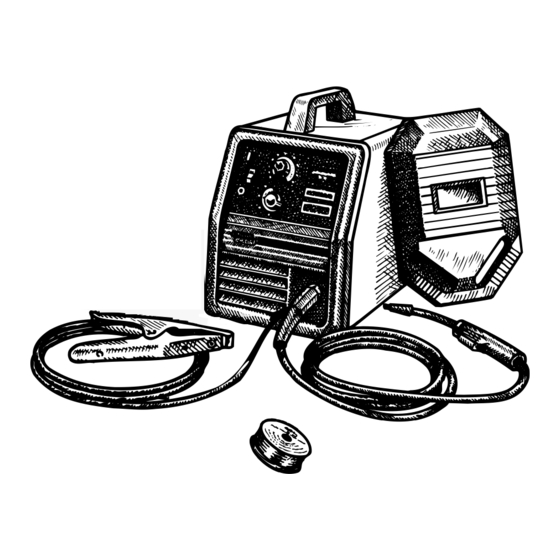
SP- 135T
April, 2004
For use with machine Code Number:10971
Safety Depends on You
Lincoln arc welding and cutting
equipment is designed and built
with safety in mind. However, your
overall safety can be increased by
proper installation ... and thought-
ful operation on your part. DO
NOT INSTALL, OPERATE OR
REPAIR THIS EQUIPMENT
WITHOUT
READING
THIS
MANUAL AND THE SAFETY
PRECAUTIONS CONTAINED
THROUGHOUT. And, most
importantly, think before you act
and be careful.
OPERATOR'S MANUAL
Copyright © 2004 Lincoln Global Inc.
• World's Leader in Welding and Cutting Products •
• Sales and Service through Subsidiaries and Distributors Worldwide •
Cleveland, Ohio 44117-1199 U.S.A. TEL: 216.481.8100 FAX: 216.486.1751 WEB SITE: www.lincolnelectric.com
Advertisement
Table of Contents

Related Manuals for Lincoln Electric SP-135T


Summary of Contents for Lincoln Electric SP-135T
- Page 1 RETURN TO MAIN MENU IM785 SP- 135T April, 2004 For use with machine Code Number:10971 Safety Depends on You Lincoln arc welding and cutting equipment is designed and built with safety in mind. However, your overall safety can be increased by proper installation ...
-
Page 2: California Proposition 65 Warnings
351040, Miami, Florida 33135 or CSA Standard W117.2-1974. A Free copy of “Arc Welding Safety” booklet E205 is available from the Lincoln Electric Company, 22801 St. Clair Avenue, Cleveland, Ohio 44117-1199. BE SURE THAT ALL INSTALLATION, OPERATION, MAINTENANCE AND REPAIR PROCEDURES ARE PERFORMED ONLY BY QUALIFIED INDIVIDUALS. -
Page 3: Electric Shock Can Kill
ELECTRIC SHOCK can kill. 3.a. The electrode and work (or ground) circuits are electrically “hot” when the welder is on. Do not touch these “hot” parts with your bare skin or wet clothing. Wear dry, hole-free gloves to insulate hands. - Page 4 WELDING SPARKS can cause fire or explosion. 6.a. Remove fire hazards from the welding area. If this is not possible, cover them to prevent the welding sparks from starting a fire. Remember that welding sparks and hot materials from welding can easily go through small cracks and openings to adjacent areas.
- Page 5 PRÉCAUTIONS DE SÛRETÉ Pour votre propre protection lire et observer toutes les instruc- tions et les précautions de sûreté specifiques qui parraissent dans ce manuel aussi bien que les précautions de sûreté générales suivantes: Sûreté Pour Soudage A L’Arc 1. Protegez-vous contre la secousse électrique: a.
- Page 6 The code number is especially important when identifying the correct replacement parts. - Register your machine with Lincoln Electric either via fax or over the Internet. • For faxing: Complete the form on the back of the warranty statement included in the literature packet accompanying this machine and fax the form per the instructions printed on it.
-
Page 7: Table Of Contents
Gun and Cable Maintenance...D-2 Component Replacement Procedures ...D-3 Changing Liner ...D-4 Gun Handle Parts ...D-4 Troubleshooting ...Section E Safety Precautions...E-1 How to Use Troubleshooting Guide...E-1 Troubleshooting Guide...E-2 THRU E-4 Wiring Diagrams ...Section F SP-135T Wiring Diagram ...F-1 Parts Lists ...P451 Series, P202-E Page... -
Page 8: Installation
TECHNICAL SPECIFICATIONS – SP-135T Standard Voltage/Frequency 120V/60Hz Duty Cycle 20% Duty Cycle Welding Current Range 25-135 Amps RECOMMENDED INPUT CABLE AND FUSE SIZES Output Mode Input Voltage RATED 120V/60Hz Height 12.0 in 305 mm If connected to a circuit protected by fuses use Time Delay Fuse marked “D”. -
Page 9: Identify And Locate Components
• Machine must be plugged into a receptacle which is grounded per any national, local or other applicable electrical codes. • The SP-135T power switch is to be in the OFF (“O”) position when installing work cable and gun and when connecting power cord to input power. -
Page 10: Select Suitable Location
SELECT SUITABLE LOCATION Locate the welder in a dry location where there is free circulation of clean air into the louvers in the back and out the front of the unit. A location that minimizes the amount of smoke and dirt drawn into the rear louvers reduces the chance of dirt accumulation that can block air passages and cause overheating. -
Page 11: Gas Connection
(4). FIGURE A.4 GUN INSTALLATION As shipped from the factory, the SP-135T is ready to feed .023" – .025" (0.6 mm) solid wire. If .030- .035"(0.8-0.9mm) solid wire is to be used, change the contact tip to the appropriate size. - Page 12 Connect the other end to the SP-135T Gas Solenoid Inlet Fitting (5/8-18 female threads — for CGA — 032 fitting). Make certain the gas hose is not kinked or twisted.
-
Page 13: Input Connections
INPUT CONNECTIONS Refer to Figure A.6. The SP-135T has a power input cable located on the rear of the machine. GAS SOLENOID INLET FITTING FIGURE A.6 CODE REQUIREMENTS FOR INPUT CONNECTIONS WARNING This welding machine must be connected to a power source in accordance with applicable elec- trical codes. -
Page 14: Operation
RECOMMENDED PROCESSES The SP-135T can be used for welding mild steel using the Gas Metal Arc Welding (GMAW or MIG, Metal Inert Gas) single pass process, which requires a sup- ply of shielding gas, or the flux-cored arc welding (FCAW) process using Innershield ®... -
Page 15: Welding Capability
Accommodates both 4” (100 mm) diameter and 8” (200 mm) diameter spools of wire. WELDING CAPABILITY The SP-135T is rated at 90 amps, 19 volts, at 20% duty cycle on a ten minute basis. It is capable of high- er output currents at lower duty cycles. -
Page 16: Welding Operations
OFF (“O”) position before working inside the wire feed enclosure. The welder is shipped from the factory ready to feed 8" (200 mm) diameter spools with 2.2" (56 mm) maxi- mum width. These spools fit on a 2" (51 mm) diameter... - Page 17 11. Turn the SP-135T OFF (“O”). 12. Replace contact tip and gas nozzle. 13. Refer to Figure B-6. Cut the wire off 3/8” – 1/2” (10 – 13 mm) from the end of the tip. The SP-135T is now ready to weld. Gun Handle FIGURE B.5...
- Page 18 PROCESS GUIDELINES The SP-135T can be used for welding mild steel using the GMAW, single pass, process which requires a supply of shielding gas or it can be used for the self- shielded, Innershield ®...
-
Page 19: Overload Protection
The circuit breaker must be manually reset. Thermal Protection The SP-135T has a rated output duty cycle of 20%. If the duty cycle is exceeded, a thermal protector will shut off the output until the machine cools to a reason- able operating temperature. -
Page 20: Application Chart
APPLICATION CHART SP-135T... -
Page 21: Accessories
4. Remove gas nozzle (if installed) and install gasless nozzle. To remove, simply unscrew. 5. Load wire into machine and thread into gun and cable per “Welding Wire Loading” section. The factory installed Gun Liner will feed .025-.035 (0.6-0.9mm) wire. SP-135T and tip for the wire size... -
Page 22: Replacement Parts
Gas Nozzle KP1938-1 Gas Nozzle-Tip Recessed 3/8” (9.5 mm) Opening I.D. KP1942-1 Gas Nozzle-Tip Recessed 1/2” (12.7 mm) Opening I.D. KP1942-2 Gas Nozzle-Tip Recessed 5/8” (15.9 mm) Opening I.D. KP1942-3 Spot Welding Nozzle KP1956-1 Gasless Nozzle (Innershield Only) KP1939-1 SP-135T... -
Page 23: Maintenance
POWER SOURCE COMPARTMENT No user serviceable parts inside! Do not attempt to perform service in the power source (fixed) side of the SP-135T. Take the unit to an authorized Lincoln Service Center if you experi- ence problems. NO maintenance is required. -
Page 24: Gun And Cable Maintenance
Use the wire as a reamer to remove dirt that may be adhering to the wall of the hole through the tip. CONFIGURATION OF COMPONENTS IN WIRE FEEDING SYSTEM Components shipped with SP-135T• K549-1 .035” (0.9mm) Innershield Welding Kit K664-2 .035 (0.9mm) Aluminum or Stainless Kit* •... -
Page 25: Component Replacement Procedures
Make certain the set screw is located on the flat portion of the shaft and tighten. SP-135T FIGURE D.1... -
Page 26: Changing Liner
See Figure D-3. SP-135T Counter-clockwise FIGURE D.3... -
Page 27: Troubleshooting
HOW TO USE TROUBLESHOOTING GUIDE Service and Repair should only be performed by Lincoln Electric Factory Trained Personnel. Unauthorized repairs performed on this equipment may result in danger to the technician and machine operator and will invalidate your factory warranty. For your safety and to avoid Electrical Shock, please observe all safety notes and precautions detailed throughout this manual. - Page 28 2. Check for obstructions in air flow. Check Gun Trigger connec- tions. See Installation section. 3. Gun trigger may be faulty. CAUTION SP-135T RECOMMENDED COURSE OF ACTION If all recommended possible areas of misadjustment have been checked and the problem persists,...
- Page 29 1. Check gas supply, flow regulator and gas hoses. 2. Check gun connection to machine for obstruction or leaky seals. CAUTION SP-135T RECOMMENDED COURSE OF ACTION If all recommended possible areas of misadjustment have been checked and the problem persists,...
- Page 30 6. Check gun for damage or breaks. 7. Check for proper drive roll orien- tation and alignment. 8. Check liner for proper size. CAUTION SP-135T RECOMMENDED COURSE OF ACTION If all recommended possible areas of misadjustment have been checked and the problem persists,...
- Page 31 DIAGRAMS NOTE: This diagram is for reference only. It may not be accurate for all machines covered by this manual. The specific diagram for a particular code is pasted inside the machine on one of the enclosure panels. SP-135T...
- Page 32 NOTES SP-135T...
- Page 33 NOTES SP-135T...
- Page 34 ● WARNING ● Spanish ● AVISO DE PRECAUCION ● French ● ATTENTION ● ● German WARNUNG ● Portuguese ● ATENÇÃO ● Japanese Chinese Korean Arabic ● ● ● ● ● ● ● ● ● ●...
- Page 35 ● ● ● ● ● ● ● ● ● ● ● ● ● ● ● ● ● ● Spanish ● PRECAUCION French ● ATTENTION ● German WARNUNG Portuguese ● ● Japanese Chinese Korean Arabic WARNING AVISO DE ATENÇÃO...
- Page 36 • World's Leader in Welding and Cutting Products • • Sales and Service through Subsidiaries and Distributors Worldwide • Cleveland, Ohio 44117-1199 U.S.A. TEL: 216.481.8100 FAX: 216.486.1751 WEB SITE: www.lincolnelectric.com...