Table of Contents
Advertisement
Quick Links
RETURN TO MAIN MENU
IM788
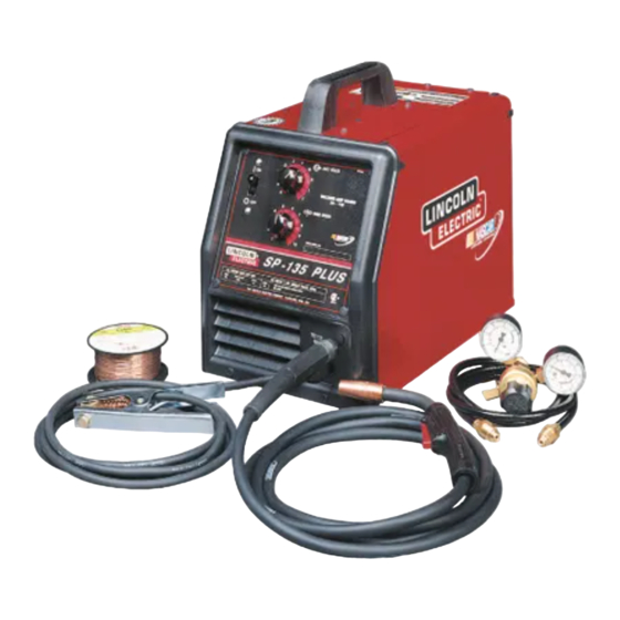
SP- 135 PLUS
July, 2005
For use with machine Code Numbers : 10974
Safety Depends on You
Lincoln arc welding and cutting
equipment is designed and built
with safety in mind. However, your
overall safety can be increased by
proper installation ... and thought-
ful operation on your part. DO
NOT INSTALL, OPERATE OR
REPAIR THIS EQUIPMENT
WITHOUT
READING
THIS
MANUAL AND THE SAFETY
PRECAUTIONS CONTAINED
THROUGHOUT. And, most
importantly, think before you act
and be careful.
OPERATOR'S MANUAL
ISO 9001
ANSI RAB
QMS
Designed and Manufactured Under a
Quality Program Certified by
ABS Quality Evaluations, Inc.
to ISO 9001 Requirements.
CERTIFICATE NUMBER: 30273
Copyright © 2005 Lincoln Global Inc.
• World's Leader in Welding and Cutting Products •
• Sales and Service through Subsidiaries and Distributors Worldwide •
Cleveland, Ohio 44117-1199 U.S.A. TEL: 216.481.8100 FAX: 216.486.1751 WEB SITE: www.lincolnelectric.com
Advertisement
Table of Contents
Troubleshooting

Related Manuals for Lincoln Electric IM788


Summary of Contents for Lincoln Electric IM788
- Page 1 RETURN TO MAIN MENU IM788 SP- 135 PLUS July, 2005 For use with machine Code Numbers : 10974 Safety Depends on You Lincoln arc welding and cutting equipment is designed and built with safety in mind. However, your overall safety can be increased by proper installation ...
-
Page 2: California Proposition 65 Warnings
351040, Miami, Florida 33135 or CSA Standard W117.2-1974. A Free copy of “Arc Welding Safety” booklet E205 is available from the Lincoln Electric Company, 22801 St. Clair Avenue, Cleveland, Ohio 44117-1199. BE SURE THAT ALL INSTALLATION, OPERATION, MAINTENANCE AND REPAIR PROCEDURES ARE PERFORMED ONLY BY QUALIFIED INDIVIDUALS. -
Page 3: Electric Shock Can Kill
ELECTRIC SHOCK can kill. 3.a. The electrode and work (or ground) circuits are electrically “hot” when the welder is on. Do not touch these “hot” parts with your bare skin or wet clothing. Wear dry, hole-free gloves to insulate hands. - Page 4 WELDING SPARKS can cause fire or explosion. 6.a. Remove fire hazards from the welding area. If this is not possible, cover them to prevent the welding sparks from starting a fire. Remember that welding sparks and hot materials from welding can easily go through small cracks and openings to adjacent areas.
- Page 5 PRÉCAUTIONS DE SÛRETÉ Pour votre propre protection lire et observer toutes les instructions et les précautions de sûreté specifiques qui parraissent dans ce manuel aussi bien que les précautions de sûreté générales suiv- antes: Sûreté Pour Soudage A L’Arc 1. Protegez-vous contre la secousse électrique: a.
- Page 6 The code number is especially important when identifying the correct replacement parts. - Register your machine with Lincoln Electric either via fax or over the Internet. • For faxing: Complete the form on the back of the warranty statement included in the literature packet accompanying this machine and fax the form per the instructions printed on it.
-
Page 7: Table Of Contents
Installation ...Section A Technical Specifications ...A-1 Identify and Locate Components ...A-2 Select Suitable Location ...A-3 Output Connections ...A-3 Input Connections...A-5 Code Requirements ...A-6 Operation ...Section B Safety Precautions ...B-1 General Description ...B-2 Design Features and Advantages...B-2 Welding Capability ...B-2 Limitations ...B-2 Controls and Settings...B-2 Welding Operations ...B-3 Overload Protection ...B-7... -
Page 8: Installation
TECHNICAL SPECIFICATIONS – SP-135 PLUS Standard Voltage/Frequency 115V/60Hz Duty Cycle 20% Duty Cycle – Rated DC Output Welding Current Range (Continuous) Maximum Open Circuit Voltage Rated DC Output: 25 – 135 Amps RECOMMENDED INPUT CABLE AND FUSE SIZES Output Mode Input Voltage RATED 115V/60Hz... -
Page 9: Identify And Locate Components
Read entire installation section before starting installation. SAFETY PRECAUTIONS WARNING ELECTRIC SHOCK can kill. • Only qualified personnel should perform this installation. • Only personnel that have read and under- stood the SP-135 PLUS Operating Manual should install and operate this equipment. •... -
Page 10: Select Suitable Location
SELECT SUITABLE LOCATION Locate the welder in a dry location where there is free circulation of clean air into the louvers in the back and out the front of the unit. A location that minimizes the amount of smoke and dirt drawn into the rear louvers reduces the chance of dirt accumulation that can block air passages and cause overheating. -
Page 11: Gas Connection
3. Route the cable under and around the back of the Wire Feed Gearbox (6). 4. For GMAW Only: Refer to Figure A.2. As deliv- ered, the SP-135 PLUS is wired for positive polari- ty. This is the appropriate configuration for the Gas Metal Arc Welding (GMAW) process. -
Page 12: Input Connections
Keep cylinder upright and chained to support • Keep cylinder away from areas where it may be damaged. • Never lift welder with cylinder attached. • Never allow welding electrode to touch cylinder. • Keep cylinder away from welding or other live electrical circuits. -
Page 13: Code Requirements
CODE REQUIREMENTS FOR INPUT CONNECTIONS WARNING This welding machine must be connected to power source in accordance with applicable elec- trical codes. The National Electrical Code provides standards for amperage handling capability of supply con- ductors based on duty cycle of the welding source. -
Page 14: Operation
Read entire Operation section before operating the SP-135 PLUS. Observe all safety information throughout this manual. OPERATION WARNING ELECTRIC SHOCK can kill. • Do not touch electrically live parts or electrode with skin or wet clothing. Insulate yourself from work and ground. •... -
Page 15: General Description
GENERAL DESCRIPTION The SP-135 PLUS is a complete semiautomatic con- stant voltage DC arc welding machine. Included is a solid state controlled, single phase constant voltage transformer/ rectifier power source and a wire feeder for feeding solid steel electrode and cored electrode. The SP-135 PLUS is ideally suited for individuals hav- ing access to 115 volt AC input power, and wanting the ease of use, quality and dependability of both gas... -
Page 16: Welding Operations
FIGURE B.1a WELDING AMP RANGE 25-125 WELDING AMP RANGE 25-125 SP-135 Plus 4. Circuit Breaker – Protects machine from damage if maximum output is exceeded. Button will extend out when tripped (Manual reset). 5. Gun Trigger - Activates welding output, wire feed, and gas solenoid operation. - Page 17 Wire Spindle Shaft To wire drive FIGURE B.3 Friction Brake Adjustment With wire spool installed on the spindle shaft and the wing nut loose, turn the spool by hand while slowly tightening the wing nut until a light drag is felt. Tighten the wing nut an additional 1/4 turn.
- Page 18 FIGURE B.5 Gun Handle Gas Diffuser Contact Tip Gas Nozzle Shielding Gas When using the GMAW process, a cylinder of shield- ing gas, must be obtained. Refer to the ACCES- SORIES section for more information about selecting gas cylinders for use with the SP-135 PLUS. 1.
- Page 19 9. To stop welding, release the gun trigger and then pull the gun away from the work after the arc goes out. 10. When no more welding is to be done, close valve on gas cylinder (if used), momentarily operate gun trigger to release gas pressure, and turn off the SP-135 PLUS.
-
Page 20: Overload Protection
OPERATION OVERLOAD PROTECTION Output Overload The SP-135 PLUS is equipped with a circuit breaker which protects the machine from potential damage from excessive output current. The circuit breaker but- ton will extend out when tripped. The circuit breaker must be manually reset. Thermal Protection The SP-135 PLUS duty cycle is exceeded a thermo- stat will shut off the output until the machine cools to a... -
Page 21: Application Chart
APPLICATION CHART SP-135 PLUS... -
Page 22: Accessories
OPTIONAL ACCESSORIES 1. K520 Utility Cart — Designed to transport the Lincoln family of small welders. Has provisions for mounting a single gas cylinder. Has front casters and large rear wheels. Handle height is easily adjustable. Bottom tray provided for tools and accessories. -
Page 23: Replacement Parts
INNERSHIELD (FCAW) CONVERSION Several changes are needed to convert the unit for operation with the Innershield (FCAW) process. The K549-1 Innershield Kit includes all the necessary accessories for this conversion and are provided for this purpose. The following conversions should be made using the contents of this kit: 1. -
Page 24: Maintenance
Excessive pressure at start may cause the dirt to form a plug. PERIODICALLY AS REQUIRED • Blow dirt out of the welder with low pressure air to eliminate excessive dirt and dust buildup that could cause welder to run hot. -
Page 25: Gun And Cable Maintenance
GUN AND CABLE MAINTENANCE FOR MAGNUM™ 100L GUN Gun Cable Cleaning Clean cable liner after using approximately 300 lbs (136 kg) of solid wire or 50 lbs (23 kg) of flux-cored wire. Remove the cable from the wire feeder and lay it out straight on the floor. -
Page 26: Component Replacement Procedures
COMPONENT REPLACEMENT PROCEDURES CHANGING THE CONTACT TIP 1. Unplug or turn power switch to Off “O” position. 2. Refer to Figure D.2. Remove the gas nozzle from the gun by unscrewing counter-clockwise. 3. Remove the existing contact tip from the gun by unscrewing counter-clockwise. -
Page 27: Changing Liner
Slotted Brass Cable Set Screw Connector Liner Assembly (Liner bushing to be seated tight against brass cable connector) FIGURE D.2 Liner trim length for gun with red trigger (Magnum™ 100L) CHANGING LINER NOTICE: The variation in cable lengths prevents the interchangeability of liners. -
Page 28: Troubleshooting
HOW TO USE TROUBLESHOOTING GUIDE Service and Repair should only be performed by Lincoln Electric Factory Trained Personnel. Unauthorized repairs performed on this equipment may result in danger to the technician and machine operator and will invalidate your factory warranty. For your safety and to avoid Electrical Shock, please observe all safety notes and precautions detailed throughout this manual. -
Page 29: Troubleshooting Guide
Fan operates normally. If for any reason you do not understand the test procedures or are unable to Perform the tests/repairs safely, contact your LOCAL AUTHORIZED LINCOLN ELECTRIC FIELD SERVICE FACILITY for assistance before you proceed. TROUBLESHOOTING POSSIBLE AREAS OF... - Page 30 If for any reason you do not understand the test procedures or are unable to Perform the tests/repairs safely, contact your LOCAL AUTHORIZED LINCOLN ELECTRIC FIELD SERVICE FACILITY for assistance before you proceed. TROUBLESHOOTING TROUBLESHOOTING GUIDE...
- Page 31 Arc is unstable – Poor starting If for any reason you do not understand the test procedures or are unable to Perform the tests/repairs safely, contact your LOCAL AUTHORIZED LINCOLN ELECTRIC FIELD SERVICE FACILITY for assistance before you proceed. TROUBLESHOOTING...
-
Page 32: Wiring Diagrams
WIRING DIAGRAMS NOTE: This diagram is for reference only. It may not be accurate for all machines covered by this manual. The specific diagram for a particular code is pasted inside the machine on one of the enclosure panels. SP-135 PLUS... - Page 33 ● WARNING ● Spanish ● AVISO DE PRECAUCION ● French ● ATTENTION ● ● German WARNUNG ● Portuguese ● ATENÇÃO ● Japanese Chinese Korean Arabic ● ● ● ● ● ● ● ● ● ●...
- Page 34 ● ● ● ● ● ● ● ● ● ● ● ● ● ● ● ● ● ● Spanish ● PRECAUCION French ● ATTENTION ● German Portuguese ● ● Japanese Chinese Korean Arabic WARNING AVISO DE WARNUNG ATENÇÃO...
- Page 35 • World's Leader in Welding and Cutting Products • • Sales and Service through Subsidiaries and Distributors Worldwide • Cleveland, Ohio 44117-1199 U.S.A. TEL: 216.481.8100 FAX: 216.486.1751 WEB SITE: www.lincolnelectric.com...