Table of Contents
Advertisement
Quick Links
10163,10261,10264,10272,10482,10691,10692,10741,10842 and 10848
Safety Depends on You
Lincoln arc welding and cutting
equipment is designed and built
with safety in mind. However,
your overall safety can be
increased by proper installation ...
and thoughtful operation on your
part. DO NOT INSTALL, OPER-
ATE OR REPAIR THIS EQUIP-
MENT WITHOUT READING
THIS MANUAL AND THE SAFE-
TY PRECAUTIONS CONTAINED
THROUGHOUT. And, most
importantly, think before you act
and be careful.
Date of Purchase:
Serial Number:
Code Number:
Model:
Where Purchased:
• Sales and Service through Subsidiaries and Distributors Worldwide •
Cleveland, Ohio 44117-1199 U.S.A. TEL: 216.481.8100 FAX: 216.486.1751 WEB SITE: www.lincolnelectric.com
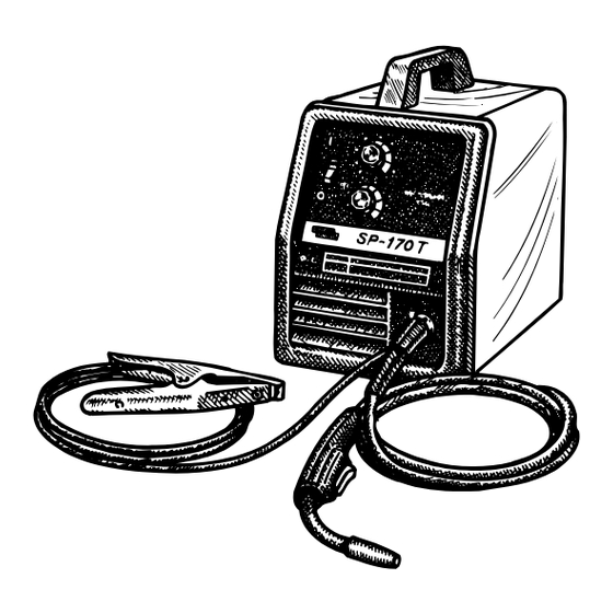
SP 170T
For use with machine Code Numbers
10026,10134,10162,
OPERATOR'S MANUAL
• World's Leader in Welding and Cutting Products •
10023; 10024; 10025;
IM537-
March, 2001
Advertisement
Table of Contents

Related Manuals for Lincoln Electric 10023


Summary of Contents for Lincoln Electric 10023
- Page 1 IM537- SP 170T March, 2001 10023; 10024; 10025; For use with machine Code Numbers 10026,10134,10162, 10163,10261,10264,10272,10482,10691,10692,10741,10842 and 10848 Safety Depends on You Lincoln arc welding and cutting equipment is designed and built with safety in mind. However, your overall safety can be increased by proper installation ...
- Page 2 351040, Miami, Florida 33135 or CSA Standard W117.2-1974. A Free copy of “Arc Welding Safety” booklet E205 is available from the Lincoln Electric Company, 22801 St. Clair Avenue, Cleveland, Ohio 44117-1199. BE SURE THAT ALL INSTALLATION, OPERATION, MAINTENANCE AND REPAIR PROCEDURES ARE PERFORMED ONLY BY QUALIFIED INDIVIDUALS.
- Page 3 SAFETY ARC RAYS can burn. ELECTRIC SHOCK can 4.a. Use a shield with the proper filter and cover kill. plates to protect your eyes from sparks and 3.a. The electrode and work (or ground) circuits the rays of the arc when welding or observing are electrically “hot”...
- Page 4 SAFETY WELDING SPARKS can CYLINDER may explode cause fire or explosion. if damaged. 6.a. Remove fire hazards from the welding area. 7.a. Use only compressed gas cylinders If this is not possible, cover them to prevent containing the correct shielding gas for the the welding sparks from starting a fire.
- Page 5 SAFETY zones où l’on pique le laitier. PRÉCAUTIONS DE SÛRETÉ 6. Eloigner les matériaux inflammables ou les recouvrir afin de Pour votre propre protection lire et observer toutes les instructions prévenir tout risque d’incendie dû aux étincelles. et les précautions de sûreté specifiques qui parraissent dans ce manuel aussi bien que les précautions de sûreté...
- Page 6 Thank You for selecting a QUALITY product by Lincoln Electric. We want you to take pride in operating this Lincoln Electric Company product ••• as much pride as we have in bringing this product to you! Please Examine Carton and Equipment For Damage Immediately When this equipment is shipped, title passes to the purchaser upon receipt by the carrier.
-
Page 7: Table Of Contents
TABLE OF CONTENTS Page Installation .......................Section A Technical Specifications ..................A-1 Safety Precautions....................A-2 Identify and Locate Components ................A-2 Select Suitable Location ..................A-3 Output Connections ....................A-3 Work Clamp Installation ..................A-3 Work Cable Installation ...................A-3 Gun Installation......................A-4 Gas Connection .....................A-4 Input Connections....................A-5 Line Cord Connection ....................A-6 230 Volt Input Connection ..................A-6 208 Volt Input Connection ..................A-6 Operation ......................Section B... -
Page 8: Installation
INSTALLATION TECHNICAL SPECIFICATIONS – SP-170T INPUT – SINGLE PHASE ONLY Standard Voltage/Frequency Input Current 230V/60Hz 20 Amps – Rated Output 208V/60Hz 22 Amps – Rated Output RATED OUTPUT Duty Cycle Amps Volts at Rated Amperes 20% Duty Cycle @ 230V/60Hz 20% Duty Cycle @ 208V/60Hz OUTPUT Welding Current Range... -
Page 9: Safety Precautions
INSTALLATION FIGURE A.1 SAFETY PRECAUTIONS Read entire installation section before starting installation. WARNING ELECTRIC SHOCK can kill. • Only qualified personnel should perform this installation. • Only personnel that have read and under- stood the SP-170T Operating Manual should install and operate this equipment. •... -
Page 10: Select Suitable Location
INSTALLATION SELECT SUITABLE LOCATION 6. Wire Feed Gearbox. 7. Cable Hanger. Locate the welder in a dry location where there is free circulation of clean air into the louvers in the back and 8. Thumbscrew. out the front of the unit. A location that minimizes the amount of smoke and dirt drawn into the rear louvers Refer to the Accessories Section for available optional reduces the chance of dirt accumulation that can block... -
Page 11: Work Cable Installation
INSTALLATION Work Cable Installation NOTE: If .035" or .045" (0.9 mm or 1.2 mm) Innershield flux-cored wire is to be used, the appropri- Refer to Figure A.2. ate Innershield kit is required. (see ACCESSORIES section) 1. Open the wire feed section door on the right side of the SP-170T. -
Page 12: Input Connections
INSTALLATION 2. With the cylinder securely installed, remove the WARNING cylinder cap. Stand to one side away from the out- let and open the cylinder valve very slightly for an CYLINDER may explode if dam- instant. This blows away any dust or dirt which may aged. -
Page 13: Line Cord Connection
INSTALLATION ELECTRICAL INPUT CONNECTION FOR Line Cord Connection RATED OUTPUT A 3 conductor line cord with a 50 amp, 250 volt, three- prong plug (NEMA Type 6-50P) is factory installed. WARNING Connect this plug to a mating grounded receptacle which is connected to an appropriate power supply ELECTRIC SHOCK can kill. -
Page 14: Operation
OPERATION SAFTEY PRECAUTIONS GENERAL DESCRIPTION Read entire operation section before The SP-170T is a complete semiautomatic constant voltage DC portable arc welder. Included is a tap- operating the SP-170T. switch controlled, single phase constant voltage trans- former/rectifier power source and a wire feeder with welding gun for feeding .023"... -
Page 15: Welding Capability
OPERATION Reversible, dual groove drive roll, shipped ready 4. Circuit Breaker – Protects machine from damage if to feed .023"/.025" (0.6 mm) diameter wire. The maximum output is exceeded. Button will extend drive roll is easily reversed to feed .030" (0.8 mm) out when tripped (Manual reset) (See Figure B.1b). -
Page 16: Welding Operations
OPERATION Load an 8” (200 mm) diameter spool on the wire spool WELDING OPERATIONS spindle shown in Figure B.2. SEQUENCE OF OPERATION To use 4” (100 mm) diameter spools, the 2” (50 mm) diameter spindle must be removed (See Figure B.3). Wire Loading Remove the wing nut and spacer at the end of the Refer to Figure B.2 and B.3. -
Page 17: Wire Threading
OPERATION Note: The brake should be adjusted with a spool of FIGURE B.4 wire installed. When properly adjusted it should move freely but not coast. Friction Brake Adjustments 1. With wire spool installed, check free movement and coast of the spool. 2. -
Page 18: Making A Weld
OPERATION FIGURE B.7 FIGURE B.6 Contact Tip GUN CABLE Wire Electrode 3/8" – 1/2" Electrical Stickout WORKPIECE Making A Weld 1. See “Process Guidelines” in this section for selec- WORK CLAMP 10. When no more welding is to be done, close valve tion of welding wire and shielding gas and for on gas cylinder (if used), momentarily operate gun range of metal thicknesses that can be welded. -
Page 19: Welding With Gmaw
OPERATION The SP-170T is suitable for .035" aluminum wire and 2. If using a regulator with an adjustable flow meter, .023"– .035" stainless wire. Refer to Table B.1 for rec- close the gun trigger and adjust the flow to give 15 ommended procedure settings. -
Page 20: Learning To Weld
LEARNING TO WELD LEARNING TO WELD WARNING No one can learn to weld simply by reading about it. Fumes and slag generated from Skill comes only with practice. The following pages will Innershield type electrodes recom- help the inexperienced operator to understand weld- mended for use with this welding ing and develop this skill. - Page 21 LEARNING TO WELD The “arc stream” is seen in the middle of the picture. THE GMAW (MIG) WELDING ARC This is the electric arc created by the electric current flowing through the space between the end of the wire Figure B.10 illustrates the GMAW (MIG) welding arc. electrode and the base metal.
- Page 22 LEARNING TO WELD JOINT TYPES AND POSITIONS 2. Can I afford the extra expense, space, and lack of portability required for gas cylinders and gas sup- ply? Five types of welding joints are: Butt Welds, Fillet Welds, Lap Welds, Edge Welds and Corner Welds. 3.
- Page 23 B-10 B-10 LEARNING TO WELD 45° FIGURE B.12 FIGURE B.15 Penetration Welding In The Vertical Position Unless a weld penetrates close to 100% of the metal thickness, a butt weld will be weaker than the material Welding in the vertical position can be done either ver- welded together.
- Page 24 B-11 LEARNING TO WELD B-11 MACHINE SET UP FOR THE SELF-SHIELDED FCAW PROCESS 1. See PROCESS GUIDELINES in the OPERATION section for selection of welding wire and shielding gas, and for range of metal thicknesses that can be welded. 2. See the Application Guide on the inside of wire feed section door for information on setting the controls.
- Page 25 B-12 LEARNING TO WELD B-12 Contact Tip Wire Electrode FIGURE B.18 3/8 – 1/2” (10 – 12 mm) Electrical Stickout (ESO) WARNING FIGURE B.19 ARC RAYS can burn eyes and skin. The easiest way to tell whether the ESO is the cor- When using an open arc process, it rect length is by listening to its sound.
- Page 26 B-13 LEARNING TO WELD B-13 Helpful Hints For the SP-170-T, use the following: Mild Steel 16 gauge or 1/16 inch 1. For general welding, it is not necessary to weave (1.6 mm) the arc, neither forward or backward nor sideways. Weld along at a steady pace.
- Page 27 B-14 B-14 LEARNING TO WELD MACHINE SET UP FOR THE GMAW (MIG) PROCESS 1. See PROCESS GUIDELINES in the OPERATION section for selection of welding wire and shielding gas, and for range of metal thicknesses that can be welded. 2. See the Application Guide on the inside of wire FIGURE B.23 feed section door for information on setting the controls.
- Page 28 B-15 LEARNING TO WELD B-15 Helpful Hints 1. For general welding, it is not necessary to weave the arc, neither forward or backward nor sideways. Contact Tip Weld along at a steady pace. You will find it easier. 2. When welding on thin plate, you will find that you will have to increase the welding speed, whereas Wire Electrode when welding on heavy plate, it is necessary to go...
- Page 29 B-16 LEARNING TO WELD B-16 4. After you strike the arc, practice the correct electri- 2. Decrease stickout. cal stickout. Learn to distinguish it by its sound. 3. Decrease WFS (wire feed speed. 4. Decrease travel speed. 5. When you are sure that you can hold the correct electrical stickout, with a smooth “crackling”...
- Page 30 B-17 B-17 LEARNING TO WELD Proper Gun Handling Most feeding problems are caused by improper han- dling of the gun cable or electrodes. 1. Do not kink or pull the gun around sharp corners 2. Keep the gun cable as straight as practical when welding.
-
Page 31: Application Chart
B-18 B-18 APPLICATION CHART SP-170T... -
Page 32: Accessories
ACCESSORIES OPTIONAL ACCESSORIES 5. K695-1 Spot / Stitch Timer Kit — Includes spot timer to control the spot welding arc time, and a stitch timer to control the on/off cycle time of the 1. K549-1 .035" (0.9 mm) Innershield® Welding Kit arc to prevent burnthrough on thin gauge metals. -
Page 33: Replacement Parts
ACCESSORIES INNERSHIELD (FCAW) REPLACEMENT PARTS CONVERSION Complete Gun and Cable Assembly L8311-6 (K530-4) Several changes are needed to convert the unit for operation with the Innershield (FCAW) process. The Contact Tip .025” (0.6 mm) K549-1 or K549-2 Innershield Kits include all the nec- S19726-1 essary accessories for this conversion and are provid- Contact Tip .030”... -
Page 34: Maintenance
MAINTENANCE MAINTENANCE SAFETY PRECAUTIONS WARNING ELECTRIC SHOCK can kill. • Disconnect input power by removing plug from receptacle before working inside SP-170T. Use only grounded receptacle. Do not touch electrically “hot” parts inside SP-170T. • Have qualified personnel do the mainte- nance and trouble shooting work. -
Page 35: Gun And Cable Maintenance
MAINTENANCE GUN AND CABLE 2. Replace worn contact tips as required. A variable or “hunting” arc is a typical symptom of a worn con- MAINTENANCE tact tip. To install a new tip, choose the correct size contact tip for the electrode being used (wire size is FOR MAGNUM™... -
Page 36: Component Replacement Procedures
MAINTENANCE 8. Push a length of straightened welding wire through COMPONENT the wire feeder guide tubes and adjust the position REPLACEMENT of the drive roll so that the groove is centered on PROCEDURES the wire. Make certain the set screw is located on the flat portion of the shaft and tighten. - Page 37 MAINTENANCE 1-1/4 (31.8 mm) Liner Trim Length Gas Diffuser Gas Nozzle or Gasless Nozzle Set Screw Brass Cable Connector Liner Assembly (Liner bushing to be sealed tight against brass cable connector) FIGURE D.2 Liner trim length CHANGING LINER 5. Insert a new untrimmed liner into the connector end of the cable.
- Page 38 MAINTENANCE GUN HANDLE PARTS The gun handle consists of two halves that are held together with a collar on each end. To open up the handle, turn the collars approximately 60 degrees counter-clockwise until the collar reaches a stop. Then pull the collar off the gun handle.
-
Page 39: Troubleshooting
HOW TO USE TROUBLESHOOTING GUIDE WARNING Service and Repair should only be performed by Lincoln Electric Factory Trained Personnel. Unauthorized repairs performed on this equipment may result in danger to the technician and machine operator and will invalidate your factory warranty. For your safety and to avoid Electrical Shock, please observe all safety notes and precautions detailed throughout this manual. - Page 40 4. Gun trigger may be faulty. CAUTION If for any reason you do not understand the test procedures or are unable to perform the tests/repairs safely, contact your LOCAL AUTHORIZED LINCOLN ELECTRIC FIELD SERVICE FACILITY for assistance before you proceed. SP-170T...
- Page 41 CAUTION If for any reason you do not understand the test procedures or are unable to perform the tests/repairs safely, contact your LOCAL AUTHORIZED LINCOLN ELECTRIC FIELD SERVICE FACILITY for assistance before you proceed. SP-170T...
- Page 42 8. Check liner for proper size. CAUTION If for any reason you do not understand the test procedures or are unable to perform the tests/repairs safely, contact your LOCAL AUTHORIZED LINCOLN ELECTRIC FIELD SERVICE FACILITY for assistance before you proceed. SP-170T...
-
Page 43: Wiring Diagrams
WIRING DIAGRAMS SP-170T... - Page 44 NOTES SP-170T...
- Page 45 Do not touch electrically live parts or Keep flammable materials away. Wear eye, ear and body protection. electrode with skin or wet clothing. WARNING Insulate yourself from work and ground. Spanish No toque las partes o los electrodos Mantenga el material combustible Protéjase los ojos, los oídos y el AVISO DE bajo carga con la piel o ropa moja-...
- Page 46 Keep your head out of fumes. Turn power off before servicing. Do not operate with panel open or Use ventilation or exhaust to guards off. WARNING remove fumes from breathing zone. Los humos fuera de la zona de res- Spanish Desconectar el cable de ali- No operar con panel abierto o AVISO DE...
- Page 47 • World's Leader in Welding and Cutting Products • • Sales and Service through Subsidiaries and Distributors Worldwide • Cleveland, Ohio 44117-1199 U.S.A. TEL: 216.481.8100 FAX: 216.486.1751 WEB SITE: www.lincolnelectric.com...