Yamaha RX-V461 Service Manual
Av amplifier
Hide thumbs
Also See for RX-V461:
- Owner's manual (322 pages) ,
- Service manual (95 pages) ,
- Owner's manual (93 pages)
Advertisement
Quick Links
RX-V461/HTR-6040/DSP-AX461
This service manual is the RX-V461/HTR-6040/DSP-AX461 (U, C, R, K, A, L and J models).
For service manual of the RX-V461/RX-V461DAB (T, B, G and E models), please refer to the following publi-
cation number:
This manual has been provided for the use of authorized YAMAHA Retailers and their service personnel.
It has been assumed that basic service procedures inherent to the industry, and more specifically YAMAHA Products, are already
known and understood by the users, and have therefore not been restated.
WARNING:
IMPORTANT:
The data provided is believed to be accurate and applicable to the unit(s) indicated on the cover. The research, engineering, and
service departments of YAMAHA are continually striving to improve YAMAHA products. Modifications are, therefore, inevitable
and specifications are subject to change without notice or obligation to retrofit. Should any discrepancy appear to exist, please
contact the distributor's Service Division.
WARNING:
IMPORTANT:
I CONTENTS
TO SERVICE PERSONNEL .......................................... 2
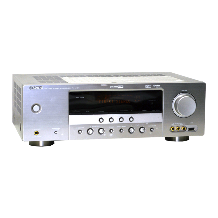
FRONT PANELS ........................................................ 3–4
REAR PANELS .......................................................... 4–7
REMOTE CONTROL PANELS ...................................... 8
SPECIFICATIONS /
INTERNAL VIEW ......................................................... 12
DISASSEMBLY PROCEDURES /
UPDATING FIRMWARE
..................................... 15–17
SELF DIAGNOSIS FUNCTION (DIAG)
..................................... 18–36
1 0 1 0 4 1
AV RECEIVER/AV AMPLIFIER
For U, C, R, K, A, L and J models
RX-V461/RX-V461DAB (T, B, G and E models): 101048
Failure to follow appropriate service and safety procedures when servicing this product may result in personal
injury, destruction of expensive components, and failure of the product to perform as specified. For these reasons,
we advise all YAMAHA product owners that any service required should be performed by an authorized
YAMAHA Retailer or the appointed service representative.
The presentation or sale of this manual to any individual or firm does not constitute authorization, certification or
recognition of any applicable technical capabilities, or establish a principle-agent relationship of any form.
Static discharges can destroy expensive components. Discharge any static electricity your body may have
accumulated by grounding yourself to the ground buss in the unit (heavy gauge black wires connect to this buss).
Turn the unit OFF during disassembly and part replacement. Recheck all work before you apply power to the unit.
.................................. 9–11
.......... 12–14
2007
This manual is copyrighted by YAMAHA and may not be copied or
redistributed either in print or electronically without permission.
SERVICE MANUAL
IMPORTANT NOTICE
DISPLAY DATA ........................................................... 37
IC DATA ................................................................. 38–52
BLOCK DIAGRAMS .............................................. 53–54
PIN CONNECTION DIAGRAMS .................................. 55
PRINTED CIRCUIT BOARDS ................................ 56–68
SCHEMATIC DIAGRAMS ...................................... 69–80
REPLACEMENT PARTS LIST .............................. 81–95
REMOTE CONTROL .............................................. 96–99
Advanced setup /
All rights reserved.
..... 100
P.O.Box 1, Hamamatsu, Japan
'07.02
Advertisement

Related Manuals for Yamaha RX-V461


Summary of Contents for Yamaha RX-V461
-
Page 1: Service Manual
For U, C, R, K, A, L and J models This service manual is the RX-V461/HTR-6040/DSP-AX461 (U, C, R, K, A, L and J models). For service manual of the RX-V461/RX-V461DAB (T, B, G and E models), please refer to the following publi- cation number:... -
Page 2: Updating Firmware
RX-V461/HTR-6040/DSP-AX461 I UPDATING FIRMWARE / After replacing the following parts with the replacement part, be sure to write the latest firmware. • DSP P.C.B. • IC201 (DSP P.C.B.) G Required Tools • DVD or CD player (with DIGITAL OUTPUT (OPTICAL or COAXIAL) terminal) •... - Page 3 RX-V461/HTR-6040/DSP-AX461 2. While pressing the “STANDBY/ON” key and “SPEAK- ERS A/B/OFF” key of the main unit simultaneously, connect the power cable of the main unit to the AC outlet. (Fig. 2) The FIRMWARE UPDATE mode will then be acti- vated and “SPDIF Upgrade” is displayed. (Fig. 2) "STANDBY/ON"...
- Page 4 RX-V461/HTR-6040/DSP-AX461 When the version of the firmware to be written is the same as the one existing in the main unit, “Same Version”, “Please...” and “Turn off!!” are displayed repeatedly. (Upgrading is not neces- sary.) If the display remains unchanged for more than...
- Page 5 RX-V461/HTR-6040/DSP-AX461 I SELF DIAGNOSIS FUNCTION (DIAG) This unit has self diagnosis functions that are intended for inspection, measurement and location of faulty point. There are 18 DIAG menu items, each of which has sub- menu items. Listed in the table below are menu items and sub-menu items.
- Page 6 RX-V461/HTR-6040/DSP-AX461 DIAG menu Sub-menu IF STATUS IF 1 (Not applied to these models.) IF 2 IF 3 IF 4 IF 5 IF 6 IF 7 IF 8 IF 9 IF 10 IF 11 IF 12 IF 13 IF 14 IF 15...
- Page 7 RX-V461/HTR-6040/DSP-AX461 • Starting DIAG Press the “STANDBY/ON” key while simultaneously pressing those two keys of the main unit as indicated in the figure below. Keys of main unit / Turn on the power while pressing these keys. / • Starting DIAG in the protection cancel mode...
- Page 8 RX-V461/HTR-6040/DSP-AX461 When there is no history of protection function: Opening message / DIAG menu display / When there is no protection history After a few seconds / NO PROTECTION 1.ANLOG BYPASS When there is a history of protection function: When there is a history of protection function due...
- Page 9 RX-V461/HTR-6040/DSP-AX461 When there is a history of protection function due to abnormal voltage in the power supply section PRV PRT:xxx AD value when the protection function is working Cause: The voltage in the power supply section is abnormal. Supplementary information: The protection function worked due to a de- fect or overload in the power supply.
- Page 10 RX-V461/HTR-6040/DSP-AX461 • Operation procedure of DIAG menu and Sub-menu There are 18 menu items, each of having sub-menu items. DIAG menu selection: Select the menu using “>” (forward) and “<” (reverse) keys of PROGRAM. Sub-menu selection: Select the sub-menu using “SCENE 2” (forward) and “SCENE 1”...
- Page 11 RX-V461/HTR-6040/DSP-AX461 • Details of DIAG menu 1. BYPASS Using the sub-menu, it is possible to select ANALOG BYPASS output or DSP BYPASS output. ANALOG BYPASS The analog input sound signal is output to FRONT L/R with EFFECT OFF. 1.ANLOG BYPASS...
- Page 12 RX-V461/HTR-6040/DSP-AX461 3. SPEAKER SET The analog switch settings for each sub-menu are as shown in the table below. FRONT : SML 0dB SMALL LARGE LARGE SWFR CENTER : NONE LARGE NONE LARGE SWFR LFE/B : FRNT LARGE SMALL SMALL FRONT...
- Page 13 RX-V461/HTR-6040/DSP-AX461 4. 6CH INPUT 4. 6CH INPUT The input source [MULTI CHANNEL INPUT] is se- lected. It is possible to select the 6-ohm/8-ohm by using the sub-menu. 6 ch INPUT 6-ohm 4.6ch INPUT 6 Ω INPUT: MULTI CH INPUT SPEAKER OUT: 1 kHz, SUBWOOFER OUTPUT: 50 Hz...
- Page 14 RX-V461/HTR-6040/DSP-AX461 6. FL/OSD CHECK Use this program to check the FL display section and video control section. When checking the video con- trol section, prepare a monitor, S video cable and video pin cable and connect them. Using the sub-menu operation, selection items of the FL display section and video display section vary as shown below.
- Page 15 RX-V461/HTR-6040/DSP-AX461 7. TEST TONE The noise generator with a built-in microprocessor outputs the noise through the channels specified by the submenu. The noise frequency for LFE (SUBWOOFER) is 35 to 80 Hz. Other than that, the noise frequency is 500 to 2 kHz.
- Page 16 RX-V461/HTR-6040/DSP-AX461 CAUTION: Before setting to the PRESET RESERVED, write down the existing preset memory con- tent of the tuner in a table as shown below. (This is because setting to the PRESET RESERVED will cause the user memory content of the tuner to be erased.) Preset Group 9.
- Page 17 RX-V461/HTR-6040/DSP-AX461 TH/PL THM (Thermo protection detection) The temperature of the heat sink is detected. Normal value: 0 to 124 (Reference volt- age: 3.3 V=255) * If THM is out of the normal value range, the protec- tion function works to turn off the power.
- Page 18 RX-V461/HTR-6040/DSP-AX461 Display / KEY0 KEY1 23 ± 4 SCENE 1 SCENE 3 42 ± 4 SCENE 2 SCENE 4 66 ± 4 PROGRAM < DIRECT 92 ± 4 PROGRAM > AUDIO SELECT 120 ± 4 STRAIGHT INPUT < 147 ± 4 TONE CONTROL INPUT >...
- Page 19 RX-V461/HTR-6040/DSP-AX461 11. DOCK This menu is used to test the DOCK connector without the iPod itself. After turning off the power, short between pins No. 14 (TX) and No. 18 (RX), between pins No. 1 (PWR) and No. 17 (ACCPOW) and between pins No. 4 (iPDET) and No.
- Page 20 RX-V461/HTR-6040/DSP-AX461 14. IF STATUS (Input function status) Not applied to these models. 14.IF • • • • • • • 14.IF 15. PROTECTION SETTING The A/D setting value of each protection is displayed. (Reference voltage: 3.3 V=255) PRD (Amplifier DC protection) Low 15.PRD L :...
- Page 21 RX-V461/HTR-6040/DSP-AX461 16. PROTECTION HISTORY Four protection histories are displayed. Example / History 1 / 16.PRI: 90 Example / History 2 / 16.PRD: 34 Example / History 3 / 16.THM: 60 Example / History 4 / 16.NO PROT...
- Page 22 RX-V461/HTR-6040/DSP-AX461 17. SOFT SWITCH Note) As this is a development menu, do not change the function setting. Changing the function setting may hinder the proper operation. This menu is used to switch the function settings on P.C.B. through the software to activate the main unit.
- Page 23 RX-V461/HTR-6040/DSP-AX461 18. ROM VER/SUM The version and checksum are displayed. The signal is processed using EFFECT OFF. The checksum is obtained by adding the data at every 8-bit for each program area and expressing the result as a 4-figure hexadecimal data.
-
Page 24: Display Data
RX-V461/HTR-6040/DSP-AX461 I DISPLAY DATA G V2001 : 17-BT-29GNK (OPERATION P.C.B.) G ANODE CONNECTION 13G-1G PATTERN AREA G PIN CONNECTION Pin No. 68 67 Connection F2 NX Pin No. Connection Note : 1) F1, F2 ..Filament pin 2) NP ..No pin 3) NX .. - Page 25 RX-V461/HTR-6040/DSP-AX461 I IC DATA IC101: ADSP-BF531 CPU (DSP P.C.B.) Pin No. Port Name Function Name Detail of Function Microprocessor DGND – Ground of external DGND – Ground of external DGND – Ground of external /VINTSW VROUT2 Voltage regulator drive for Q101...
- Page 26 RX-V461/HTR-6040/DSP-AX461 Pin No. Port Name Function Name Detail of Function TSCLK1 TSCLK1 Serial port 1, serial transmission clock DR1SEC DR1SEC Serial port 1, secondary reception data DR1PRI DR1PRI Serial port 1, primary reception data RFS1 RFS1 Serial port 1, frame synchronization reception...
- Page 27 RX-V461/HTR-6040/DSP-AX461 Pin No. Port Name Function Name Detail of Function ADDR19 SDRAM address bus 19 ADDR18 SDRAM address bus 18 ADDR17 SDRAM address bus 17 ADDR16 SDRAM address bus 16 ADDR15 SDRAM address bus 15 ADDR14 SDRAM address bus 14...
- Page 28 RX-V461/HTR-6040/DSP-AX461 • Microprocessor extended port IC204-IC207: SN74LV573APWR (DSP P.C.B.) Octal 3-state D-latches with 3-state outputs IC204 Pin No. Port Name Function Name Detail of Function /EXPE Extended port enable Data bus 00 Data bus 01 Data bus 02 Data bus 03...
- Page 29 RX-V461/HTR-6040/DSP-AX461 IC206 Pin No. Port Name Function Name Detail of Function /EXPE Extended port enable Data bus 00 Data bus 01 Data bus 02 Data bus 03 Data bus 04 Data bus 05 Data bus 06 Data bus 07 DGND...
- Page 30 RX-V461/HTR-6040/DSP-AX461 • Microprocessor ADC select port IC401: ADC084S021CIMM (DSP P.C.B.) 4-channel, 200 kSPS, 8-bit A/D converter 8-Bit SCLK SUCCESSIVE APPROXIMATION DOUT ADC084S021 SCLK CONTROL LOGIC DOUT Pin No. Port Name Function Name Detail of Function /SPISEL1 CS for microprocessor +3.3S...
- Page 31 RX-V461/HTR-6040/DSP-AX461 IC402 Pin No. Port Name Function Name Detail of Function iPAP DOCK (iPod) detect (ACCPOW) DEST2 Destination 2 * SPI bus IN4 (IC401) LINKACTIVE Link detect (U, C models) XM_MUTE XM mute (U, C models) DGND (Pull-down) DGND Ground of external...
- Page 32 RX-V461/HTR-6040/DSP-AX461 IC301: AK4588VQ (DSP P.C.B.) 2/8-channel audio CODEC with DIR PVSS PVDD X'tal Clock Oscillator 8 to 3 Recovery Clock MCKO1 Generator Input MCKO2 Selector LRCK2 DAIF Audio BICK2 Decoder SDTO2 DAUX2 AVDD AVSS DVDD Error & CCLK Q-subcode DVSS...
- Page 33 RX-V461/HTR-6040/DSP-AX461 Pin No. Function Name Detail of Function INT1 Interrupt 1 pin BOUT Block-start output pin for receiver input “H” during first 40 flames TVDD – Output buffer power supply pin, 2.7 V to 5.5 V DVDD – Digital power supply pin, 4.5 V to 5.5 V DVSS –...
- Page 34 RX-V461/HTR-6040/DSP-AX461 Pin No. Function Name Detail of Function ROUT3 DAC3 R ch analog output pin No connect pin – No internal bonding / This pin should be opened LOUT2 DAC2 L ch analog output pin No connect pin – No internal bonding / This pin should be opened...
- Page 35 RX-V461/HTR-6040/DSP-AX461 IC161: R2A15215FP (MAIN P.C.B.) 49 48 46 45 38 37 34 33 A VCC MUTE A VCC N.C. A VEE A VEE N.C. TREL 0/-6/-12/-18dB ADCL BASSL2 BASSL1 ADCR N.C. AGND Bass/Treble 0~-95dB, -14~+14dB -∞ (2dBstep) MAIN +42~0dB N.C.
- Page 36 RX-V461/HTR-6040/DSP-AX461 Pin No. Function Name Detail of Function N.C. No connected SBLC L/R/C/SW/SL/SR/SBL/SBR ch terminal to connect capacitor to reduce noise from changing the volume SBLOUT FL/FR/C/SW/SL/SR/SBL/SBR ch output terminal AGND Analog GND terminal SBROUT FL/FR/C/SW/SL/SR/SBL/SBR ch output terminal SBRC...
- Page 37 RX-V461/HTR-6040/DSP-AX461 Pin No. Function Name Detail of Function AGND Analog GND terminal N.C. No connected INR1 L/R ch input terminal (input selector) INL1 L/R ch input terminal (input selector) INR2 L/R ch input terminal (input selector) INL2 L/R ch input terminal (input selector)
- Page 38 RX-V461/HTR-6040/DSP-AX461 IC201: M66003-0131FP-R (OPERATION P.C.B.) 18 digit 5x7 segment VFD controller/driver Display code CGROM SEG00 (35 bit x 166) (8-bit x 60) Segment SEG25 Code output write SEG26 circuit CGROM SEG34 Serial dot data data (35 bit x 16) write...
- Page 39 RX-V461/HTR-6040/DSP-AX461 Pin No. Port Name Function Name Detail of Function Reset /RESET Reset input When "L", M66003 is initialized /CEFL Chip select input When "L", communication with the MCU is possible When "H", any instruction from the MCU is neglected...
- Page 40 RX-V461/HTR-6040/DSP-AX461 I BLOCK DIAGRAMS Video, Audio and Power Supply Sections • See page 69-74 → • See page 75, 76 → MAIN OPERATION SCHEMATIC DIAGRAM SCHEMATIC DIAGRAM • See page 77, 78 → • See page 79, 80 → VIDEO...
- Page 41 RX-V461/HTR-6040/DSP-AX461 Control Section • See page 75, 76 → OPERATION SCHEMATIC DIAGRAM /RESET from OPERATION CONTROL LIST /RESET Input select VIA, VIB, VIC IC505 IC505 /OSDSEL • See page 69-74 → SCHEMATIC DIAGRAM /VR1 IC202 IC201 SSEL1-3 IC204-207 Control bus...
- Page 42 RX-V461/HTR-6040/DSP-AX461 SCHEMATIC DIAGRAMS DSP 1/6 to DSP 2/6 to DSP 5/6 EEPROM to DSP 2/6 MICROPROCESSOR to DSP 5/6 to DSP 6/6 IC101 to DSP 3/6 to DSP 5/6 to DSP 4/6 to DSP 6/6 to DSP 2/6 to DSP 3/6, 4/6...
- Page 43 RX-V461/HTR-6040/DSP-AX461 DSP 2/6 to DSP 1/6 SDRAM IC203 to DSP 5/6 IC203 EXTENDED PORT to DSP 1/6 to DSP 5/6 to DSP 4/6 to DSP 4/6 1 .0 to DSP 3/6 FLASH ROM to DSP 5/6 to DSP 4/6 to DSP 5/6...
- Page 44 RX-V461/HTR-6040/DSP-AX461 DSP 3/6 IC302, 307: SN74LV157APWR Quadruple 2-line to 1-line data selectors/multiplexers DIGITAL IN IC305 IC305 (U, C, R, K, A, L models) J model Pin numbers shown are for the D, DB, DGV, J, NS, PW, and W packages.
- Page 45 RX-V461/HTR-6040/DSP-AX461 DSP 4/6 to DSP 2/6 A/D SELECTOR to DSP 3/6 DSP 5/6 to DSP 6/6 A/D SELECTOR * Destination for A/D port R416 [ohm] 1.5 k 5.6 k 1.0 k 6.8 k 100 k 3.3 k 4ch ADC R410 [ohm] 3.3 k...
- Page 46 RX-V461/HTR-6040/DSP-AX461 DSP 5/6 CB512 to DSP 1/6 to DSP 2/6 IC501: SN74AHCT08PWR Quadruple 2-input positive-AND gates Page 78 D10 to DSP 2/6 to MAIN (5)_CB161 3.3 3.3 to DSP 1/6, 2/6, 4/6 IC505: SN74LV08APWR Quadruple 2-input positive-AND gate CB501 Page 77...
- Page 47 RX-V461/HTR-6040/DSP-AX461 DSP 6/6 U, C models to DSP 1/6 to DSP 3/6 to DSP 4/6 to DSP 1/6 to DSP 5/6 DOCK (iPod) to DSP 5/6 to DSP 5/6 to DSP 2/6 to DSP 5/6 to DSP 5/6 No replacement part available.
- Page 48 MAIN (1)_W103 CB203 Page 76 to OPERATION (2)_CB235 IC202: AZ4580MTR-E1 Dual low noise operational amplifiers OPERATION (10) OUTPUT -INPUT +INPUT W2003 CB204 OPERATION (11) RX-V461/DSP-AX461 models VIDEO JK201 Page 78 to MAIN (4)_CB192 OPTIMIZER 12.0 IC202 W2351 AUDIO IC202 -11.8 JK266...
- Page 49 RX-V461/HTR-6040/DSP-AX461 OPERATION 2/2 OPERATION (5) 12.7 12.7 13.3 CB258 13.3 13.3 12.7 13.3 AC 6.9 12.7 11.7 13.1 R, L models 13.2 12.0 13.1 CB251 CB256 13.5 AC IN W2251 W251A W251B CB257 CB252 CB254 CB255 CB253 W252A W252B OPERATION (3)
- Page 50 RX-V461/HTR-6040/DSP-AX461 MAIN 1/2 POWER AMPLIFIER IC102 47.8 47.7 -46.4 FRONT L SURROUND L -12.0 SPEAKERS FRONT A 47.5 -12.0 W101A Page 80 to VIDEO (4)_CB381 -11.8 47.5 to MAIN 2/2 W103 Page 75 to OPERATION (6)_CB261 -11.8 POWER AMPLIFIER IC101 -46.4...
- Page 51 RX-V461/HTR-6040/DSP-AX461 MAIN 2/2 Page 79 Page 73 to VIDEO (2)_CB322 to DSP_CB502 Page 75 Page 75 Page 79 to OPERATION (1)_W2001 to OPERATION (7)_W2351 to VIDEO (2)_W3201 11.7 FILTER IC162 W163B ANALOG L IC162 -12.0 11.8 IC162-164, 169: AZ4580MTR-E1 Dual low noise operational amplifiers -11.9...
- Page 52 RX-V461/HTR-6040/DSP-AX461 VIDEO 1/2 Page 73 to DSP_CB504 Page 78 to MAIN (4)_CB193 INPUT SELECTOR -0.5 INPUT SELECTOR JK301 W3201 JK302 VIDEO -5.0 CB321 IC342 INPUT SELECTOR S VIDEO CB341 JK303 INPUT CB306 SELECTOR IC344 OUTPUT OUTPUT AMPLIFIER AMPLIFIER -5.0 IC344 -5.0...
- Page 53 RX-V461/HTR-6040/DSP-AX461 VIDEO 2/2 VIDEO (4) Page 77 FRONT B to MAIN (1)_W101A CB381 SPEAKERS SURROUND L SURROUND Page 77 to MAIN (1)_W102A CENTER CENTER CB382 # All voltages are measured with a 10MΩ/V DC electronic voltmeter. # Components having special characteristics are marked s and must be replaced with parts having specifications equal to those originally installed.
- Page 54 RX-V461/HTR-6040/DSP-AX461 I REMOTE CONTROL G RAV328 (U, C models) • SCHEMATIC DIAGRAM • PANEL FORMAT : NEC FORMAT CARRIER FREQ. : 37.9 kHz CARRIER DUTY : 1/3 MMST4403 TP26 MUSIC SUR. DECODE LEVEL/BAND XM MEMORY TITLE RETURN LTE3271TA TP25 LED1...
- Page 55 RX-V461/HTR-6040/DSP-AX461 • KEY NO. LAYOUT • KEY CODE AMP library Code Function Key Label Common MAIN ZONE2 MAIN ZONE2 – – – O (10sec) – O (10sec) Linked with IR signal CODE SET – – – – – Change to PRESET mode...
- Page 56 RX-V461/HTR-6040/DSP-AX461 G RAV310 (R, K, A, L, J models) • SCHEMATIC DIAGRAM • PANEL REW (SEARCH -) FF (SEARCH +) SKIP+ PLAY PAUSE SKIP- STOP 100 ohms LEFT RETURN SELECT VOL down DISPLAY RIGHT DOWN IR Diode ENTER ZLR32300H2832G SCENE...
- Page 57 RX-V461/HTR-6040/DSP-AX461 • KEY NO. LAYOUT • KEY CODE Command YAMAHA signal Label TV POWER – – (TV Power) (TV Power) (TV Power) (TV Power) – (TV Power) (TV Power) (TV Power) (TV Power) (TV Power) (TV Power) (TV Power) –...