Table of Contents
Advertisement
RETURN TO MAIN MENU
IM906
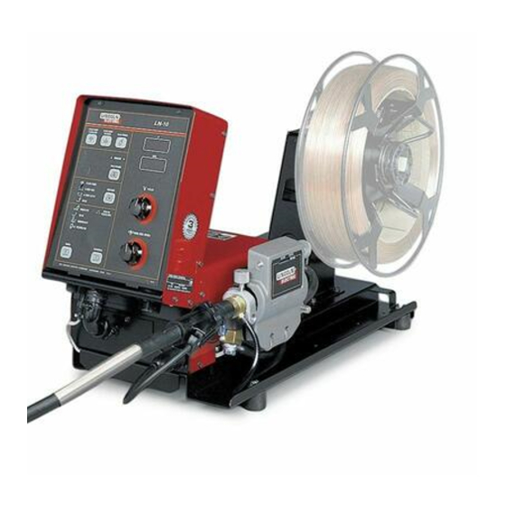
LN- 10 Heads & Controls
August, 2007
Bench Model
For use with: LN-10 Bench Model Code - 11368
Safety Depends on You
Lincoln arc welding and cutting
equipment is designed and built
with safety in mind. However, your
overall safety can be increased by
proper installation ... and thought-
ful operation on your part. DO
NOT INSTALL, OPERATE OR
REPAIR THIS EQUIPMENT
WITHOUT
READING
THIS
MANUAL AND THE SAFETY
PRECAUTIONS CONTAINED
THROUGHOUT. And, most
importantly, think before you act
and be careful.
OPERATOR'S MANUAL
Copyright © 2007 Lincoln Global Inc.
• World's Leader in Welding and Cutting Products •
• Sales and Service through Subsidiaries and Distributors Worldwide •
Cleveland, Ohio 44117-1199 U.S.A. TEL: 216.481.8100 FAX: 216.486.1751 WEB SITE: www.lincolnelectric.com
Advertisement
Table of Contents
Troubleshooting

Related Manuals for Lincoln Electric LN-10


Summary of Contents for Lincoln Electric LN-10
- Page 1 RETURN TO MAIN MENU IM906 LN- 10 Heads & Controls August, 2007 Bench Model For use with: LN-10 Bench Model Code - 11368 Safety Depends on You Lincoln arc welding and cutting equipment is designed and built with safety in mind. However, your overall safety can be increased by proper installation ...
-
Page 2: California Proposition 65 Warnings
351040, Miami, Florida 33135 or CSA Standard W117.2-1974. A Free copy of “Arc Welding Safety” booklet E205 is available from the Lincoln Electric Company, 22801 St. Clair Avenue, Cleveland, Ohio 44117-1199. BE SURE THAT ALL INSTALLATION, OPERATION, MAINTENANCE AND REPAIR PROCEDURES ARE PERFORMED ONLY BY QUALIFIED INDIVIDUALS. -
Page 3: Electric Shock Can Kill
ELECTRIC SHOCK can kill. 3.a. The electrode and work (or ground) circuits are electrically “hot” when the welder is on. Do not touch these “hot” parts with your bare skin or wet clothing. Wear dry, hole-free gloves to insulate hands. - Page 4 WELDING and CUTTING SPARKS can cause fire or explosion. 6.a. Remove fire hazards from the welding area. If this is not possible, cover them to prevent the welding sparks from starting a fire. Remember that welding materials from welding can easily go through small cracks and openings to adjacent areas.
- Page 5 PRÉCAUTIONS DE SÛRETÉ Pour votre propre protection lire et observer toutes les instructions et les précautions de sûreté specifiques qui parraissent dans ce manuel aussi bien que les précautions de sûreté générales suiv- antes: Sûreté Pour Soudage A LʼArc 1. Protegez-vous contre la secousse électrique: a.
- Page 6 Electric for advice or information about their use of our products. We respond to our customers based on the best information in our posses- sion at that time. Lincoln Electric is not in a position to warrant or guarantee such advice, and assumes no liability, with respect to such infor- mation or advice.
-
Page 7: Table Of Contents
Water Connections (For Water Cooled Guns) ...A-4 10 Series Wire Drives ...A-4 GMAW Shielding Gas ...A-5 Gas Guard Regulator ...A-5 Electrical Installation...A-5 Input Cable: LN-10 Control to Power Source ...A-5 Work Cable ...A-5 Optional Features Installation...A-6 ________________________________________________________________________________ Operation ...Section B Safety Precautions ...B-1... -
Page 8: Installation
Bench Model 6.0 Amps 50/60 Hz (K1559-5) • Excluding Wire Reel GENERAL DESCRIPTION The LN-10 is a modular line of 42VAC input 4-roll wire feed- ers. A single control with dual procedure presettability of wire feed speed (in IPM or M/min) and arc voltage is used with a single DC welding power source. -
Page 9: Safety Precautions
Control Speed Range Setting The speed range is set up to match the wire feed head connected to the LN-10 control by properly set- ting the switch (S1) code on the control board inside the control box. See OPERATION “Setting the DIP Switches”... -
Page 10: Wire Feed Drive Roll Kits
500 ampere K289. All gun cable lengths are 15 ft. (4.5 m). These guns will feed electrode sizes .062" (1.6 mm) to 3/32" (2.4 mm) and require the use of the K184 vacuum unit for use with the LN-10. LN-10... -
Page 11: Gun Cable Connection With Standard Connection
(L.E. Part No. S19663) are provided in the Kit for installation on 3/16" (5 mm) I.D. hose (Customer to provide appropriate clamps). The feeder connectors self seal when disconnected. LN-10 (FOR WATER must have a K590-4 Water... -
Page 12: Gmaw Shielding Gas
2) Connect the electrode lead to the power source output terminal of the desired polarity. 3) Connect the 9-socket plug of the control cable to the mating receptacle on the bottom of the LN-10 control box. 4) Slip the current sensor cover off enough to expose the input connector stud. -
Page 13: Optional Features Installation
Feed Speed and Voltage, along with a dual procedure selector switch, when the remote control is connected and REMOTE is selected by the LN-10 Procedure key. The LN-10 A or B procedure light will also be on to indicate which procedure is selected by the remote control. -
Page 14: Operation
Observe all additional Safety Guidelines detailed throughout this manual. DUTY CYCLE The LN-10 models are rated at 60% duty cycle * for a maximum current of 600 amps. * Based on a 10 minute time period (6 minutes on, and 4 minutes off). -
Page 15: Welding Power Source Selection
Head M 4 S R + - Wire Drive Head Selection The LN-10 control is set up for proper presettable wire feed speed by setting S1 DIP switches (5 to 8) as appropriate per the following examples for the head... -
Page 16: Step Trigger Mode Operation Selection
Kit. OPERATION Metric/English Wire Feed Speed Display Selection The LN-10 Control is set up for Wire Feed Speed dis- play in Metric units (m/min.) or English units (IPM) by setting S2 DIP Switch 1 (Labeled “M”): S2 switch 1 OFF = IPM (as shipped) -
Page 17: Maximum Limits Setting Mode Selection
S2 switch 3 OFF = Security mode OFF (as shipped) M 4 S R + - Robotics Mode Selection The LN-10 control is set up for Robotics Mode by set- ting the S2 DIP Switch 4 (Labeled “R”). For Robotics Interface Mode to operate, a K1561-1 Robotics Interface Module must be installed. -
Page 18: Keypad And Display Operation
OPERATION Power-Down Save Power to the LN-10 is supplied and controlled from the power source. The LN-10 automatically senses the loss of power when the power source is turned off. Dual procedure settings, including; trigger mode, cold... -
Page 19: Trigger Mode Selection
Voltage and Wire Feed Speed are again being dis- played, and set by the appropriate encoder knob. LN-10 Top Light - indicates preflow time is being displayed, set 0.0 to 2.5 seconds (0.2 sec as shipped). This... - Page 20 LN-10 with all Timer and Control settings as desired for both procedures for both Feeders. Then setting S2 DIP switch 3 inside the LN-10 Control Box ON or OFF and restor- ing input power (See “Setting DIP Switches” in this section).
-
Page 21: Maximum And Minimum Limits Setting Modes
1. Turn off the power at the power source. 2. Remove the two screws at the top of the LN-10 control box and open the control box door. 3. Put DIP switch S2 switch 5 in the ON position. -
Page 22: Dual Procedure Remote Control (K1449-1
(K1449-1) remote, both the front panel and remote Procedure selector and switch must be set to “REMOTE” and “Gun Switch” (center) positions. The LN-10 Procedure lights indicate whether A or B is remotely selected. WIRE REEL LOADING - READI-REELS, SPOOLS OR COILS To Mount a 30 Lb. -
Page 23: Feeding Electrode And Brake Adjustment
Do not overtighten. DRIVE ROLL PRESSURE SETTING The LN-10 pressure is factory pre-set to about posi- tion “2" as shown on the pressure indicator on the front of the feedplate door. This is an approximate... -
Page 24: Procedure For Setting Angle Of Feedplate
Key counterclockwise to the desired gas flow rate. MAKING A WELD 1) Use only a Lincoln Electric recommended constant voltage DC power source compatible with the LN- 10 Wire Feeder. 2) Properly connect the electrode and work leads for the correct electrode polarity. -
Page 25: Wire Reel Changing
2) Disconnect the gun cable from the gun connector on the LN-10 wire drive unit and lay the gun and cable out straight. 3) Using pliers to grip the wire, pull it out of the cable from the connector end. -
Page 26: Explanation Of Prompting And Error Messages
Indicates one or more of the recalled settings is out of acceptable limits. Press any key to return to nor- mal operation. Be sure to check all voltage, wire feed speed, acceleration and timer settings before you proceed. LN-10 B-13... -
Page 27: Accessories
KP1505 - 7/64H (2.8mm) KP1505 - 7/64 (3.0mm) KP1505 - 120 (0.9 mm) KP1507 - 035A (1.0 mm) KP1507 - 040A (1.2 mm) KP1507 - 3/64A (1.6 mm) KP1507 - 1/16A (1.0 mm) --------------- (1.2 mm) --------------- (1.6 mm) --------------- LN-10... -
Page 28: Input Cable Assemblies
Includes a remote control box with a 16 ft. (5 m) length control cable with 4-pin plug for the mating receptacle on the bottom of the LN-10 control box. The remote con- trol box contains a procedure selector switch and 2... -
Page 29: Gun And Cable Assemblies
K613-2 connector kit, and install a K1500-3 gun connection kit to the wire feeder. Lincoln Innershield and Sub Arc Guns All of these guns can be connected to the LN-10 by using the K1500-1 Adapter Kit. Lincoln Fume Extraction Guns The K556 (250XA) and K566 (400XA) guns require that a K489-9 Fast-Mate adapter kit be installed. - Page 30 (representing weld- ing operation in process). K1561-1 ROBOTICS INTERFACE MODULE The module plugs directly into the LN-10 control board and provides an interface to a properly equipped Fanuc robot. When installed and properly configured, the K1561-1 Robotics Interface Module allows com- plete control of the welding process from the robot controller.
-
Page 31: Maintenance
2) Loosen the retaining screw, which is also accessed from bottom of feeder, using a 3/16" Allen wrench. Continue to loosen the screw until the feedplate can be easily pulled off of the wire feeder. LN-10... -
Page 32: How To Use Troubleshooting Guide
HOW TO USE TROUBLESHOOTING GUIDE Service and Repair should only be performed by Lincoln Electric Factory Trained Personnel. Unauthorized repairs performed on this equipment may result in danger to the technician and machine operator and will invalidate your factory warranty. For your safety and to avoid Electrical Shock, please observe all safety notes and precautions detailed throughout this manual. -
Page 33: Troubleshooting
6. Poor gas shielding on processes requiring gas. 7. Improper power source selection on the control p.c. board. CAUTION LN-10 RECOMMENDED COURSE OF ACTION If all recommended possible areas of misadjustment have been checked and the problem persists, Contact your local Lincoln... - Page 34 3. Damaged control p.c. board 1. Power source is unable to provide arc voltage because of thermal shutdown or other failure. CAUTION LN-10 RECOMMENDED COURSE OF ACTION If all recommended possible areas of misadjustment have been checked and the problem persists, Contact your local Lincoln Authorized Field Service Facility.
- Page 35 2. Damaged keypad 3. Damaged display p.c. board. 3. Damaged control p.c. board. CAUTION LN-10 RECOMMENDED COURSE OF ACTION If all recommended possible areas of misadjustment have been checked and the problem persists, Contact your local Lincoln Authorized Field Service Facility.
- Page 36 2. Damaged keypad 3. Damaged display p.c. board. 4. Damaged control p.c. board. CAUTION LN-10 RECOMMENDED COURSE OF ACTION If all recommended possible areas of misadjustment have been checked and the problem persists, Contact your local Lincoln Authorized Field Service Facility.
- Page 37 2. Power source supply is not sup- plying 42 VAC to the wire feeder control box. 3. Damaged input power wiring in the LN-10 control box. 4. Damaged control p.c. board. 1. The connectors from the control p.c. board to the display p.c.
- Page 38 2. Disconnected or damaged wiring between the wire drive and con- trol box. 3. Damaged wiring in the LN-10 wire drive. 4. Damaged wiring in the LN-10 con- trol box. 5. Damaged control p.c. board.
- Page 39 1. Inlet gas pressure exceeding 80 psi(5.5 bar). Verify that gas pres- sure regulator is operating proper- CAUTION LN-10 RECOMMENDED COURSE OF ACTION If all recommended possible areas of misadjustment have been checked and the problem persists, Contact your local Lincoln Authorized Field Service Facility.
-
Page 40: Procedure For Replacing Pc Boards
If PC board is visibly damaged mechanically, inspect for cause, then remedy before installing a replacement PC board. If there is damage to the PC board or if replacing PC board corrects problem, return it to the local can kill. Lincoln Electric Field Service Shop. CAUTION... -
Page 41: Diagrams
DIAGRAMS LN-10... - Page 42 DIAGRAMS LN-10...
-
Page 43: Dimension Print
DIAGRAMS DIMENSION PRINT LN-10... - Page 44 NOTES LN-10...
- Page 45 NOTES LN-10...
- Page 46 ● WARNING ● Spanish ● AVISO DE PRECAUCION ● French ● ATTENTION ● ● German WARNUNG ● Portuguese ● ATENÇÃO ● Japanese Chinese Korean Arabic ● ● ● ● ● ● ● ● ● ●...
- Page 47 ● ● ● ● ● ● ● ● ● ● ● ● ● ● ● ● ● ● Spanish ● PRECAUCION French ● ATTENTION ● German WARNUNG Portuguese ● ● Japanese Chinese Korean Arabic WARNING AVISO DE ATENÇÃO...
- Page 48 • World's Leader in Welding and Cutting Products • • Sales and Service through Subsidiaries and Distributors Worldwide • Cleveland, Ohio 44117-1199 U.S.A. TEL: 216.481.8100 FAX: 216.486.1751 WEB SITE: www.lincolnelectric.com...