Table of Contents
Advertisement
Quick Links
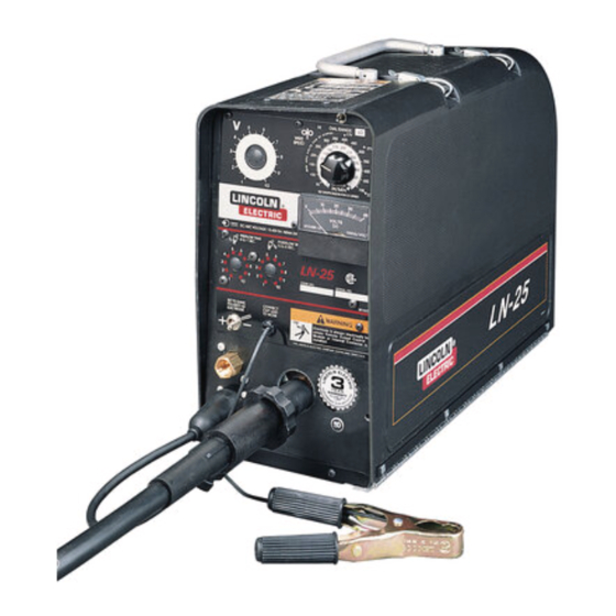
LN-25 PORTABLE CV/CC
SEMIAUTOMATIC WIRE FEEDER
Safety Depends on You
Lincoln arc welding and cutting
equipment is designed and built
with safety in mind. However, your
overall safety can be increased by
proper installation ... and thought-
ful operation on your part. DO NOT
INSTALL, OPERATE OR REPAIR
THIS EQUIPMENT WITHOUT
READING THIS MANUAL AND
THE SAFETY PRECAUTIONS
CONTAINED
THROUGHOUT.
And, most importantly, think before
you act and be careful.
World's Leader in Welding and Cutting Products
• Sales and Service through Subsidiaries and Distributors Worldwide •
Cleveland, Ohio 44117-1199 U.S.A. TEL: 216.481.8100 FAX: 216.486.1751 WEB SITE: www.lincolnelectric.com
For use with machines having Code Number
RETURN TO MAIN MENU
OPERATING MANUAL
10231
10232
10233
Premier Manufacturer of Industrial Motors
IM359-G
February, 1998
Advertisement
Table of Contents
Troubleshooting

Related Manuals for Lincoln Electric IM359-G


Summary of Contents for Lincoln Electric IM359-G
- Page 1 World's Leader in Welding and Cutting Products • Sales and Service through Subsidiaries and Distributors Worldwide • Cleveland, Ohio 44117-1199 U.S.A. TEL: 216.481.8100 FAX: 216.486.1751 WEB SITE: www.lincolnelectric.com 10231 10232 10233 RETURN TO MAIN MENU Premier Manufacturer of Industrial Motors IM359-G February, 1998...
-
Page 2: Safety
“Safety in Welding & Cutting - ANSI Standard Z49.1” from the American Welding Society, P.O. Box 351040, Miami, Florida 33135 or CSA Standard W117.2-1974. A Free copy of “Arc Welding Safety” booklet E205 is available from the Lincoln Electric Company, 22801 St. Clair Avenue, Cleveland, Ohio 44117-1199. -
Page 3: Electric Shock Can Kill
ELECTRIC SHOCK can kill. 3.a. The electrode and work (or ground) circuits are electrically “hot” when the welder is on. Do not touch these “hot” parts with your bare skin or wet clothing. Wear dry, hole-free- gloves to insulate hands. - Page 4 WELDING SPARKS can cause fire or explosion. 6.a. Remove fire hazards from the welding area. If this is not possible, cover them to prevent the welding sparks from starting a fire. Remember that welding sparks and hot materials from welding can easily go through small cracks and openings to adjacent areas.
- Page 5 PRÉCAUTIONS DE SÛRETÉ Pour votre propre protection lire et observer toutes les instructions et les précautions de sûreté specifiques qui parraissent dans ce manuel aussi bien que les précautions de sûreté générales suiv- antes: Sûreté Pour Soudage A L’Arc 1. Protegez-vous contre la secousse électrique: a.
- Page 6 This statement appears where the information must be followed to avoid minor personal injury or dam- age to this equipment. LN-25 for selecting a QUALITY product by Lincoln Electric. We want you to take pride in operating this Lincoln Electric Company product ••• as much pride as we have in bringing this product...
-
Page 7: Table Of Contents
TABLE OF CONTENTS SAFETY ...i-iv INSTALLATION ...SECTION A Technical Specifications...A-1 Safety Precautions ...A-2 Power Source Connections ...A-2 Gun Cable Connection to Feeder ...A-3 Weld Cable Connection...A-4 Electrode Cable Connection ...A-4 Work Cable Connection ...A-4 Wire Feed Drive Roll and Guide Tube Kits ...A-4 OPERATION ...SECTION B Safety Precautions ...B-1 General Description...B-1... -
Page 8: Installation
TECHNICAL SPECIFICATIONS – LN-25 Constant Voltage (CV) Constant Current (CC) Rated current without contactor Rated current with contactor RECOMMENDED ELECTRODE WIRE SIZES ⁄ ” .023” to ⁄ ” .045” to ⁄ ” 035” to HEIGHT (Handle Down) 14 Inches (354 mm) OPERATION: - 40 STORAGE:... -
Page 9: Safety Precautions
SAFETY PRECAUTIONS WARNING Unless an optional output control or contactor is used with the LN-25, the electrode circuit (including welding wire, wire drive and welding gun) is electrically hot when the welding power source is on. The gun trigger controls wire feed only. Disconnect or shut off welding power source before making connections or installations to the LN-25. -
Page 10: Gun Cable Connection To Feeder
Set ELECTRODE POLARITY switch to constant voltage polarity required by electrode. d. Set toggle switch to “Constant Voltage” and set the Constant Voltage Control on welder and the portable field control on #5 for initial start. SA-200, —250 OR SAE-300, —400 (WITH CV ADAPTER) a. -
Page 11: Weld Cable Connection
Install the barbed fitting and union nut to the female inert gas fitting on the front panel of the LN-25 case. Connect the ⁄ ” I.D. gas hose from the gun cable to the barbed fitting. When the gun is to be removed, this fitting can be easily detached by loosening the union nut. -
Page 12: Operation
SAFETY PRECAUTIONS READ AND UNDERSTAND ENTIRE SECTION BEFORE OPERATING MACHINE WARNING ELECTRIC SHOCK can kill. • Do not touch electrically live part or electrode with skin or wet clothing. • Insulate yourself from work and ground. • Always wear dry insulating gloves. - Page 13 LN-25 INSTRUMENTS AND CONTROLS Refer to Figure B.1 for control locations. REMOTE WIRE SPEED ARC VOLTAGE DIAL RANGE CONTROL SWITCH (OPTIONAL) GAS POST/ PRE FLOW TIMERS (OPTIONAL) ELECTRODE POLARITY SWITCH FITTING (OPTIONAL) TRIGGER AMPHENOL CONNECTOR FIGURE B.1 CONTROL LOCATIONS VOLTMETER (Factory installed on model Codes above 9218) The 40V DC analog voltmeter is mounted to the front control panel of the LN-25 and is connected to read...
- Page 14 wire speed is set to 400 in/min., a welding procedure arc voltage of at least 17V would be required to obtain the 400 in/min. wire feed speed. WORK CLIP LEAD WARNING ELECTRIC SHOCK can kill. • Do not touch metal portions of the LN-25 lead clip when welding power source is on.
-
Page 15: Sequence Of Operation
SEQUENCE OF OPERATION LOADING ELECTRODE WARNING ELECTRIC SHOCK can kill. • Unless an optional output control or internal contactor is used with the LN-25, the electrode circuit is electri- cally “Hot” when the power source is on. • Turn off the power source while mounting electrode coils. -
Page 16: Loading Wire Drive
1. Press end of gun against a solid object that is electrically isolated from the welder output. Press the gun trigger for several seconds. 2. If the wire “birdnests,” jams or breaks at the drive roll, the idle roll pressure is too great. -
Page 17: Presetting Wire Feed Speed
3. If the only result is drive roll slippage, shut off the power source, then loosen the gun cable clamping screw in the gearbox conductor block and pull the gun cable forward about six inches. There should be a slight waviness in the exposed wire. -
Page 18: Making A Weld
Arc Volts Used Desired In/Min 131 117 105 153 136 123 111 102 175 156 140 127 117 108 100 197 175 158 143 131 121 113 105 219 194 175 159 146 135 125 117 109 103 241 214 193 175 160 148 138 128 120 113 263 233 210 191 175 162 150 140 131 124 284 253 228 207 190 175 163 152 142 134 306 272 245 223 204 188 175 163 153 144... -
Page 19: Procedure At End Of Coil
• Keep cylinder upright and chained to support. • Keep cylinder away from areas where it may be dam- aged. • Never lift welder with cylin- der attached • Never allow welding elec- trode to touch cylinder. • Keep cylinder away from welding or other live electri- cal circuits. -
Page 20: Automatic Protection Shutdown
CAUTION Do not use LN-25 models below Code 9200 with any TIG or Square Wave welding power sources. Do not use LN-25 models equipped with internal contactors with non-Lincoln TIG or Square Wave welding power sources. Damage to the LN-25 circuit can occur as a result of the high output inductance typically associated with these power sources. -
Page 21: Accessories
K431-1, K432 or K433 remote output control system, or K443-1 internal contactor kit. This feature and the use of a DC Constant Voltage welder provide an added margin of safety when welding must be performed under electrically hazardous conditions such as: •... -
Page 22: Options And Accessories
• Keep cylinder upright and • Keep cylinder away from areas where it may be damaged. • Never lift welder with cylinder attached. • Never allow welding electrode to touch cylin- der. • Keep cylinder away trom welding or other live electrical circuits. -
Page 23: K460-1 Pulse Power Adapter Kit
Installation instructions (M17590) are included with this kit. K460-1 PULSE POWER ADAPTER KIT (For use with K461 Pulse Power Control Cable.) This kit enables the LN-25 to pulse weld with a Pulse Power 500 power source above Code 9300 (or lower Codes updated with S18506 Kit). -
Page 24: K432 Remote Control Cable Assembly
The Remote Box provides the proper welding power source control interface and isolated 24V AC input supply for the LN-25 equipped with the K431-1 Remote Output Control Kit. Remote Box requires 115V AC, 50/60 Hz input and a welding power source using a contact closure output pilot circuit, as available on appropriate Lincoln welding power sources. -
Page 25: K444, K444-1 Or K444-2 Remote Voltage Control Kit
ACCESSORIES K444, K444-1 OR K444-2 REMOTE VOLTAGE CONTROL KIT (Not required if using K431-1 or K624-1 Remote Output Control Kit or K460-1 Pulse Power Adapter Kit.) The Remote Voltage Control Kit provides remote (10K ohm rheostat) control of power source output arc voltage level. - Page 26 The following Figures C.1 and C.2 should serve as a guide to determine if a particular gun or switch can be connected to the LN-25. GUN CABLE CONNECTOR REQUIREMENTS TO PERMIT PROPER CONNECTION TO LINCOLN LN-25 WIRE FEEDER. NOTE: Connector part with .749/.747 diameter should be made from brass if it is to be part of the welding current carrying circuit.
-
Page 27: Maintenance
SAFETY PRECAUTIONS WARNING ELECTRIC SHOCK can kill. • Do not operate with covers removed. • Turn off power source before installing or servicing. • Do not touch electrically hot parts. • Turn the input power to the welding power source off at the fuse box before working in the terminal strip. -
Page 28: Calibration Of The Ln-25 Wire Speed Dial
device is not screwed in far enough, the LN-25 motor speed could be unstable or run at full speed with no control. If screwed in too far, it will rub a moving part inside the gearbox. The module is properly mounted to the gearbox as shipped from the factory. -
Page 29: How To Use The Troubleshooting Guide
HOW TO USE TROUBLESHOOTING GUIDE Service and Repair should only be performed by Lincoln Electric Factory Trained Personnel. Unauthorized repairs performed on this equipment may result in danger to the technician and machine operator and will invalidate your factory warranty. For your safety and to avoid Electrical Shock, please observe all safety notes and precautions detailed throughout this manual. -
Page 30: Troubleshooting
PROBLEMS (SYMPTOMS) No wire feed when gun trigger is pulled Wire feeds for a short time but stops feeding. When gun trigger is released and retriggered wire feeding starts but stops again. Wire feeds OK, but stubs or stops while welding. If for any reason you do not understand the test procedures or are unable to perform the tests/repairs safely, contact your local authorized field service facility for technical troubleshooting assistance before you proceed. - Page 31 PROBLEMS (SYMPTOMS) Rough wire feeding or wire not feeding but drive rolls turning. If for any reason you do not understand the test procedures or are unable to perform the tests/repairs safely, contact your local authorized field service facility for technical troubleshooting assistance before you proceed. TROUBLESHOOTING POSSIBLE AREAS OF MISADJUSTMENT(S)
- Page 32 PROBLEMS (SYMPTOMS) Solenoid does not close when trigger is pulled or purge button is pressed. Wire feeds properly. Variable or “hunting” arc. Weld porosity, narrow and ropey bead, or electrode stubbing into plate when welding. Motor feeds but there is no wire feed speed control.
-
Page 33: Wiring Diagram
WIRING DIAGRAM MAR97 LN-25... -
Page 34: Ln-25 Physical Dimensions
DIMENSIONS LN-25 PHYSICAL DIMENSIONS 16.60 14.00 21.00 7.40 LN-25 4/96...