Table of Contents
Advertisement
Quick Links
IM10084
RETURN TO MAIN MENU
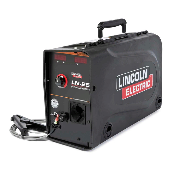
LN- 25™ IRONWORKER
April, 2011
For use with machines having Code Number: 11752
Safety Depends on You
Lincoln arc welding and cutting
equipment is designed and built
with safety in mind. However, your
overall safety can be increased by
proper installation ... and thoughtful
operation on your part. DO NOT
INSTALL, OPERATE OR REPAIR
THIS EQUIPMENT WITHOUT
READING THIS MANUAL AND
THE SAFETY PRECAUTIONS
CONTAINED THROUGHOUT.
And, most importantly, think before
you act and be careful.
IP23
IEC 60974-5
OPERATOR'S MANUAL
Copyright © Lincoln Global Inc.
• World's Leader in Welding and Cutting Products •
• Sales and Service through Subsidiaries and Distributors Worldwide •
Cleveland, Ohio 44117-1199 U.S.A. TEL: 216.481.8100 FAX: 216.486.1751 WEB SITE: www.lincolnelectric.com
Advertisement
Table of Contents

Related Manuals for Lincoln Electric LN- 25 IM10084


Summary of Contents for Lincoln Electric LN- 25 IM10084
- Page 1 IM10084 RETURN TO MAIN MENU LN- 25™ IRONWORKER April, 2011 For use with machines having Code Number: 11752 Safety Depends on You Lincoln arc welding and cutting equipment is designed and built with safety in mind. However, your overall safety can be increased by proper installation ...
-
Page 2: California Proposition 65 Warnings
351040, Miami, Florida 33135 or CSA Standard W117.2-1974. A Free copy of “Arc Welding Safety” booklet E205 is available from the Lincoln Electric Company, 22801 St. Clair Avenue, Cleveland, Ohio 44117-1199. bE SURE THAT ALL INSTALLATION, OPERATION, MAINTENANCE AND REPAIR PROCEDURES ARE PERFORMED ONLY bY QUALIFIED INDIVIDUALS. - Page 3 SAFETY...
- Page 4 SAFETY...
- Page 5 PRÉCAUTIONS DE SÛRETÉ Pour votre propre protection lire et observer toutes les instructions et les précautions de sûreté specifiques qui parraissent dans ce manuel aussi bien que les précautions de sûreté générales suiv- antes: Sûreté Pour Soudage A L’Arc 1. Protegez-vous contre la secousse électrique: a.
- Page 8 Electric for advice or information about their use of our products. We respond to our customers based on the best information in our posses- sion at that time. Lincoln Electric is not in a position to warrant or guarantee such advice, and assumes no liability, with respect to such infor- mation or advice.
-
Page 9: Table Of Contents
TAbLE OF CONTENTS –––––––––––––––––––––––––––––––––––––––––––––––––––––––––––––––––––––––––––––––– Installation...Section A Technical Specifications ...A-1 Safety Precautions ...A-2 Location ...A-2 High Frequency Protection ...A-2 Weld cable Sizes ...A-2 Cable Connections , Shielding Gas Connection ...A-3 Wire Drive Configuration ...A-4 Changing The Gun Receiver Bushing ...A-4 Procedure to Install Drive Rolls and Wire Guides ...A-4 Pressure Arm Adjustment ...A-5 Loading Spools of Wire ...A-5 Gun Connections...A-5... -
Page 10: Installation
TECHNICAL SPECIFICATIONS – LN-25™ IRONWORKER (K2614-9) INPUT VOLTAGE and CURRENT INPUT VOLTAGE ± 10% 15-110 VDC RATED OUTPUT @ 104°F (40°C) DUTY CYCLE 60% rating GEARING - WIRE FEED SPEED RANGE-WIRE SIzE GEARING WFS RANGE Standard Speed 50 – 700 ipm K2614-5 (1.3 –... -
Page 11: Safety Precautions
Table A.1 located below are copper cable sizes rec- ommended for different currents and duty cycles. Lengths stipulated are the distance from the welder to work and back to the welder again. Cable sizes are increased for greater lengths primarily for the purpose of minimizing cable drop. -
Page 12: Cable Connections
• Keep cylinder away from areas where it may be damaged. • Never lift welder with cylinder attached. • Never allow welding electrode to touch cylinder. • Keep cylinder away from welding or other live electrical circuits. -
Page 13: Wire Drive Configuration
WIRE DRIVE CONFIGURATION (See Figure A.2) CHANGING bUSHING WARNING ELECTRIC SHOCK can kill. • Turn the input power OFF at the welding power source before instal- lation or changing drive rolls and/or guides. • Do not touch electrically live parts. •... -
Page 14: Pressure Arm Adjustment
PRESSURE ARM ADJUSTMENT WARNING ELECTRIC SHOCK can kill. • Turn the input power OFF at the weld- ing power source before installation or changing drive rolls and/or guides. • Do not touch electrically live parts. • When inching with the gun trigger, electrode and drive mechanism are "hot"... -
Page 15: Power Source To Ln-25™ Ironworker Connection Diagrams
CV-655 DC-400 DC-600 DC-655 V450-Pro SAE 400 with CV adapter Engine Driven welder with Wire Feed Module Ranger 250 GXT Place the power source Remote/Local switch in the Local position. Place CV/CC switch in the feeder in the "CV" position. - Page 16 CV Power Source with Twist-Mate Connectors and Remote/Local Switch. (See Figure A.8) CV-305 V350-Pro Place CV/CC switch in the feeder in the "CV" position. CV Power Source with Twist-Mate Connectors and no Remote/Local Switch. (See Figure A.9) Jumper CV-250 CV-300 Place CV/CC switch in the feeder in the "CV"...
-
Page 17: Operation
SAFETY PRECAUTIONS READ AND UNDERSTAND ENTIRE SECTION bEFORE OPERATING MACHINE. WARNING • ELECTRIC SHOCK CAN KILL. Unless using COLD FEED fea- ture, when feeding with gun trig- ger, the electrode and drive mechanism are always electri- cally energized and could remain energized several sec- onds after the welding ceases.. -
Page 18: Definition Of Welding Terms
General Physical Description The LN-25™ IRONWORKER is specially engineered to be the most rugged portable wire feeder available and meets the individual welder needs. The plastic case is molded from a high impact, flame retardant plastic for durability and low weight. The patent pending design keeps the internal components protected and dry. -
Page 19: Case Front Controls
(See Customer Assistance Policy in the front of this Instruction Manual) CASE FRONT CONTROLS (See Figure b.1) FIGURE b.1 ITEM DESCRIPTION Wire Feed Speed/Amperage Display Wire Feed Speed LED Amperage LED Wire Feed Speed Knob 5 pin gun trigger connector Work Clip Connection Thermal LED Voltage Display... - Page 20 Perform regular maintenance and cleaning on the gun liner, conduit and gun. Always use quality electrode, such as L-50 or L-56 from Lincoln Electric. POWER-UP SEQUENCE All of the LED’s will briefly illuminate during power-up. If the gun trigger is activated during power up, the feeder will not operate until the gun trigger is released.
- Page 21 WIRE FEED SPEED UNITS To change the wire feed speed units: Rotate the WFS knob to left “inches/minute” for the wire feed speed units. O O WFS Rotate the WFS knob to right “meters/minute” for the wire feed speed units. Then rotate the WFS knob to the 12 o’clock position.
- Page 22 LEFT DISPLAY SELECTION The left display can show either amperage or actual WFS during welding. Note that actual WFS is not the same as preset WFS. For example, the preset WFS may be set to 400 ipm, but the arc voltage is only 15V. The actual WFS will be approximately 280 ipm because there is not enough arc voltage to run at 400 ipm.
-
Page 23: Internal Controls
INTERNAL CONTROLS ITEM 2 Step Trigger Interlock Switch Pressure Adjustment Arm Optional Timer Kit (See Accessories Section) Spool Retainer Spindle Brake Gun Bushing Thumb Screw for securing the welding Gun Socket Head Cap Screw for securing the Gun Bushing Drive Hubs Inlet Wire Guide Cold Feed Pushbutton OPERATION... - Page 24 INTERNAL CONTROLS DESCRIPTION (See Figure B.2) 2 Step - Trigger Interlock Switch The 2 Step - Trigger Interlock switch changes the function of the gun trigger. 2 Step trigger opera- tion turns welding on and off in direct response to the trigger. Trigger Interlock operation allows welding to continue when the trig- ger is released for comfort on long...
-
Page 25: Rear Controls
REAR CONTROLS: ITEM Gas Purge Pushbutton Shielding Gas Inlet Electrode Lead GAS PURGE PUSHbUTTON The gas solenoid valve will energize but neither the power source output nor the drive motor will be turned on. The Gas Purge switch is useful for setting the proper flow rate of shielding gas. -
Page 26: Accessories
FACTORY INSTALLED EQUIPMENT • K1500-2 Gun Receiver Bushing. DRIVE ROLL KITS (See Parts Pages) K1803-1 Work and Feeder Cables Package. K1840-xx Weld Power Cable, Twist-Mate to Lug. K1842-xx Weld Power Cable, Lug to Lug. Jumper Plug Kit. K484 Timer Kit K2330-2 Plastic Case K2596-2... - Page 27 K910-1 Ground Clamp K910-2 Ground Clamp Gun Receiver Bushing (for guns K1500-1 with K466-1 Lincoln gun connec- tors; Innershield and Subarc guns) Gun Receiver Bushing (for guns with K466-2, K466-10 Lincoln gun K1500-2 connectors; Magnum 200/300/400 guns and compatible with Tweco® #2-#4) Gun Receiver Bushing (for guns K1500-3...
- Page 28 Gun Receiver Bushing (for gun K1500-4 with K466-3 Lincoln gun connec- tors; compatible with Miller® guns.) K1500-5 Gun Receiver Bushing (compatible with Oxo® guns.) K435 Spindle Adapter, for mounting 14 lb. (6.4 kg) Innershield Coils on 2 in (51 mm) spindles. K468 Spindle Adapter, for mounting 8in (203mm) diameter spools on 2 in...
-
Page 29: Maintenance
SAFETY PRECAUTIONS WARNING ELECTRIC SHOCK can kill. • Turn the input power OFF at the welding power source before installation or changing drive rolls and/or guides. • Do not touch electrically live parts. • When inching with the gun trigger, electrode and drive mechanism are "hot"... -
Page 30: Troubleshooting
HOW TO USE TROUbLESHOOTING GUIDE Service and Repair should only be performed by Lincoln Electric Factory Trained Personnel. Unauthorized repairs performed on this equipment may result in danger to the technician and machine operator and will invalidate your factory warranty. For your safety and to avoid Electrical Shock, please observe all safety notes and precautions detailed throughout this manual. -
Page 31: Error Codes
Observe all Safety Guidelines detailed throughout this manual PRObLEMS (SYMPTOMS) Err 81 Motor overload, long term. Err 82 Motor overload, short term. If for any reason you do not understand the test procedures or are unable to perform the tests/repairs safely, contact your Local Lincoln Authorized Field Service Facility for technical troubleshooting assistance before you proceed. - Page 32 3. Blow dirt out of the liner with low pressure (40psi or less). Replace the liner if worn. 4. Use only clean electrode. Use quality electrode, like L-50 or L-56 from Lincoln Electric. 5. Replace the contact tip. 6. Verify the proper parts are installed.
- Page 33 Observe all Safety Guidelines detailed throughout this manual PRObLEMS (SYMPTOMS) Wire feed speed consistently oper- ates at the wrong value. The speed changes when the wire feed speed knob is adjusted. The wire feed speed stuck at 200- 300 in/min and there is no change when the wire feed speed knob is adjusted.
- Page 34 DIAGRAMS LN-25™ IRONWORKER...
- Page 35 DIMENSION PRINT LN-25™ IRONWORKER...
- Page 36 NOTES LN-25™ IRONWORKER...
- Page 37 NOTES LN-25™ IRONWORKER...
- Page 40 • World's Leader in Welding and Cutting Products • • Sales and Service through Subsidiaries and Distributors Worldwide • Cleveland, Ohio 44117-1199 U.S.A. TEL: 216.481.8100 FAX: 216.486.1751 WEB SITE: www.lincolnelectric.com...