Table of Contents
Advertisement
Quick Links
RETURN TO MAIN MENU
IM833-C
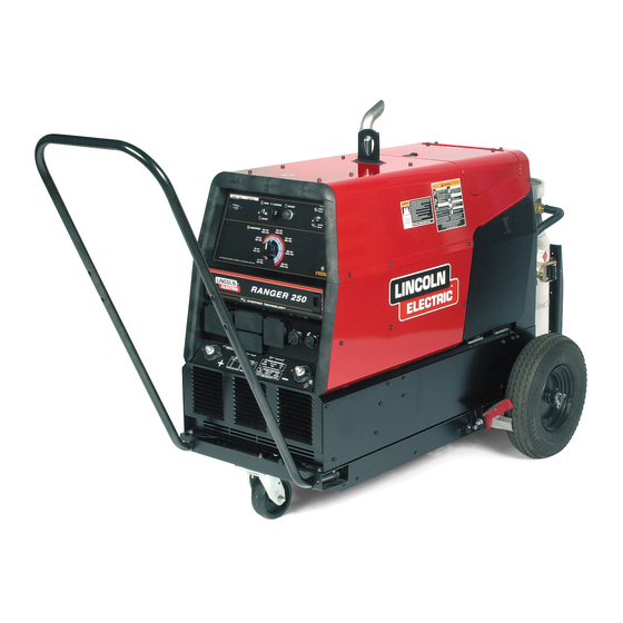
Ranger 250
June, 2005
11117, 11118, 11167, 11168, 11270, 11271
For use with machines having Code Numbers:
Safety Depends on You
Lincoln arc welding and cutting
equipment is designed and built
with safety in mind. However, your
overall safety can be increased by
proper installation ... and thought-
ful operation on your part. DO
NOT INSTALL, OPERATE OR
REPAIR THIS EQUIPMENT
WITHOUT
READING
THIS
MANUAL AND THE SAFETY
PRECAUTIONS CONTAINED
THROUGHOUT. And, most
importantly, think before you act
and be careful.
OPERATOR'S MANUAL
Copyright © 2005 Lincoln Global Inc.
• World's Leader in Welding and Cutting Products •
• Sales and Service through Subsidiaries and Distributors Worldwide •
Cleveland, Ohio 44117-1199 U.S.A. TEL: 216.481.8100 FAX: 216.486.1751 WEB SITE: www.lincolnelectric.com
Advertisement
Table of Contents

Related Manuals for Lincoln Electric RANGER 250 IM833-C


Summary of Contents for Lincoln Electric RANGER 250 IM833-C
- Page 1 RETURN TO MAIN MENU IM833-C Ranger 250 June, 2005 11117, 11118, 11167, 11168, 11270, 11271 For use with machines having Code Numbers: Safety Depends on You Lincoln arc welding and cutting equipment is designed and built with safety in mind. However, your overall safety can be increased by proper installation ...
-
Page 2: California Proposition 65 Warnings
351040, Miami, Florida 33135 or CSA Standard W117.2-1974. A Free copy of “Arc Welding Safety” booklet E205 is available from the Lincoln Electric Company, 22801 St. Clair Avenue, Cleveland, Ohio 44117-1199. BE SURE THAT ALL INSTALLATION, OPERATION, MAINTENANCE AND REPAIR PROCEDURES ARE PERFORMED ONLY BY QUALIFIED INDIVIDUALS. -
Page 3: Electric Shock Can Kill
ELECTRIC SHOCK can kill. 3.a. The electrode and work (or ground) circuits are electrically “hot” when the welder is on. Do not touch these “hot” parts with your bare skin or wet clothing. Wear dry, hole-free gloves to insulate hands. - Page 4 WELDING SPARKS can cause fire or explosion. 6.a. Remove fire hazards from the welding area. If this is not possible, cover them to prevent the welding sparks from starting a fire. Remember that welding sparks and hot materials from welding can easily go through small cracks and openings to adjacent areas.
- Page 5 PRÉCAUTIONS DE SÛRETÉ Pour votre propre protection lire et observer toutes les instructions et les précautions de sûreté specifiques qui parraissent dans ce manuel aussi bien que les précautions de sûreté générales suiv- antes: Sûreté Pour Soudage A L’Arc 1. Protegez-vous contre la secousse électrique: a.
- Page 6 The code number is especially important when identifying the correct replacement parts. - Register your machine with Lincoln Electric either via fax or over the Internet. • For faxing: Complete the form on the back of the warranty statement included in the literature packet accompanying this machine and fax the form per the instructions printed on it.
-
Page 7: Table Of Contents
Welding Terminals ...A-5 Welding Output Cables ...A-5 Cable Installation...A-6 Auxiliary Power Receptacles and Plugs ...A-6 Standby Power Connections ...A-6 Premises Wiring ...A-7 Connection of Lincoln Electric Wire Feeders...A-8, A-9 ________________________________________________________________________________ Operation...Section B Safety Precautions ...B-1 General Description...B-1 Design Features ...B-1 Engine Operation ...B-1... - Page 8 Spark Plug ...D-3 Spark Plug Service ...D-3 Fuel Filter ...D-4 Engine Adjustment ...D-4 Battery Maintenance ...D-4 Option Spark Arrestor...D-4 Welder / Generator Maintenance ...D-5 Storage ...D-5 Cleaning...D-5 Brush Removal and Replacement ...D-5 ________________________________________________________________________ Troubleshooting ...Section E How to Use Troubleshooting Guide...E-1 Troubleshooting Guide ...E-2...
-
Page 9: Installation
Air Cooled Gasoline 20.5 HP Engine K1725-9 Robin-Subaru EH64 RATED OUTPUT @ 104°F(40C°) - WELDER Welding Output CC STICK & PIPE DC Output STICK / PIPE Output Range TIG Output Range CV WIRE DC Output CV WIRE DC Output CV WIRE Output Range RATED OUTPUT @ 104°F(40C°) - GENERATOR... -
Page 10: Machine Specifications
MACHINE SPECIFICATIONS - Ranger 250 (K1725-6, K1725-7, K1725-8, K1725-9) RECEPTACLES AND CIRCUIT BREAKERS RECEPTACLES AUXILIARY POWER CIRCUIT BREAKER (2) 120VAC Duplex (5-20R) (1) 120/240VAC Dual Voltage Full KVA (14-50R) INSTALLATION Two 20AMP for Two Duplex Receptacle One 40AMP for Dual Voltage (2-Pole) Below code 11270 two 40AMP cicuit breakers were used for Dual Voltage... -
Page 11: Safety Precautions
The welder should be located to provide an unrestrict- ed flow of clean, cool air to the cooling air inlets and to avoid restricting the cooling air outlets. Also, locate the welder so that the engine exhaust fumes are prop- erly vented to an outside area. STACKING Ranger 250 machines cannot be stacked. -
Page 12: Vehicle Mounting
The standard muffler included with this welder does not quali- fy as a spark arrester. When required by local regula- tions, a suitable spark arrester, such as the K1898-1 must be installed and properly maintained. -
Page 13: High Frequency Generators For Tig Applications
To prevent dangerous electric shock, other equipment to which this engine driven welder supplies power must: INSTALLATION 1. Be grounded to the frame of the welder using a grounded type plug. 2. Be double insulated. Do not ground the machine to a pipe that carries explosive or combustible material. -
Page 14: Cable Installation
Table A.1 lists recommended cable sizes and lengths for rated current and duty cycle. Length refers to the distance from the welder to the work and back to the welder. Cable diameters are increased for long cable lengths to reduce voltage drops. -
Page 15: Premises Wiring
CONNECTION OF RANGER 250 TO PREMISES WIRING 240 VOLT POWER 240 Volt 60 Hz. COMPANY 3-Wire Service METER DOUBLE POLE DOUBLE THROW SWITCH RATING TO BE THE SAME AS OR GREATER THAN PREMISES SERVICE OVERCURRENT PROTECTION. 50 AMP, 120/240 VOLT PLUG NEMA TYPE 14-50 50 AMP, 120/240 VOLT RECEPTACLE... -
Page 16: Connection Of Lincoln Electric Wire Feeders
• Shut the welder off. • For electrode Positive, connect the electrode cable to the "+" terminal of the welder and work cable to the "-" terminal of the welder. For electrode Negative, connect the electrode cable "-" terminal of the welder and work cable to the "+"... - Page 17 K1849-1 Adapter Module. 1. Shut the Welder off. 2. For electrode Positive, connect the electrode cable to the "+" terminal of the welder and work cable to the "-" terminal of the welder. For electrode Negative, connect the electrode cable "-" terminal of the welder and work cable to the "+"...
-
Page 18: Operation
• Only qualified personnel should operate this equipment. ADDITIONAL SAFETY PRECAUTIONS Always operate the welder with the hinged door closed and the side panels in place as these pro- vide maximum protection from moving parts and insure proper cooling air flow. -
Page 19: Welding Controls
WELDING CONTROLS: 1. OUTPUT CONTROL: The CONTROL dial provides continuous control of the welding current or welding voltage depending on the selected welding mode. This control is not active in the CC-STICK, DOWN HILL PIPE, and CV-WIRE modes when a remote control or wire feeder with remote control is connected to either the 6 pin or 14 pin Amphenol. -
Page 20: Engine Controls
Amphenol, the auto-sensing circuit in the Ranger 250 automatically switches the OUTPUT control from con- trol at the welder to remote control . When using the TOUCH START TIG mode with a TIG Module connected to the Ranger 250, the OUT-... -
Page 21: Stopping
NOTE: A fuel shut off valve is not required on the Ranger 250 because the fuel tank is mounted below the engine. WELDER OPERATION DUTY CYCLE is the percentage of time the load is being applied in a 10 minute period. For example, a 60% duty cycle represents 6 minutes of load and 4 minutes of no load in a 10 minute period. -
Page 22: Tig Welding
.045 (1.1 mm), Super Arc L-50 and L-56, .035 (0.9 mm) and .045 (1.1 mm) Blue Max MIG 308 LS. Contact your local authorized Lincoln Electric Distributor or the Lincoln Electric Company for specific wires used on certain applications with this machine. FOR TUNGSTEN ELECTRODES Approximate Argon Gas Flow Flow Rate C.F.H. -
Page 23: Arc Gouging
ARC GOUGING The Ranger 250 can be used for limited arc gouging. For optimal performance, set the MODE switch to CC- STICK and the ARC CONTROL to +10. Set the CONTROL knob to adjust output current to the desired level for the gouging electrode being used according to the ratings in the following table. -
Page 24: Accessories
400 amps, 100% duty cycle. K857 25 ft (7.5m) or K857-1 100 ft. (30.4m) REMOTE CON- TROL - Portable control provides same dial range as the output control on the welder. Has a convenient 6 pin plug for easy connection to the welder. ACCESSORIES... -
Page 25: Maintenance
SAFETY PRECAUTIONS WARNING • Have qualified personnel do all maintenance and troubleshooting work. • Turn the engine off before working inside the machine or servicing the engine. • Remove guards only when necessary to perform maintenance and replace them when the maintenance requiring their removal is complete. -
Page 26: Onan P220 Ohv / Robin-Subaru Engine
ENGINE OIL CHANGE Drain the oil while the engine is warm to assure rapid and complete draining. • Remove the oil filler cap and dipstick. Remove the yellow cap from the oil drain valve and attach the flexible drain tube supplied with the machine. Push in and twist the drain valve counterclockwise. -
Page 27: Air Filter Paper Element
AIR FILTER PAPER ELEMENT 1. Loosen the cover retaining knob and remove the cover. 2. Remove the pre-cleaner from the paper element. 3. Remove the element cover nut, element cover, and paper element. 4. Do not wash the paper element or use pressurized air, as this will damage the element. -
Page 28: Fuel Filter
CONNECTING A BATTERY CHARGER — • remove battery from welder by disconnecting negative cable first, then positive cable and battery clamp. When reinstalling, connect negative cable last. Keep well ventilated. -
Page 29: Welder / Generator Maintenance
WARNING • Service and Repair should only be performed by Lincoln Electric Factory Trained Personnel. Unauthorized repairs performed on this equip- ment may result in danger to the technician and machine operator and will invalidate your factory warranty. -
Page 30: Troubleshooting
HOW TO USE TROUBLESHOOTING GUIDE Service and Repair should only be performed by Lincoln Electric Factory Trained Personnel. Unauthorized repairs performed on this equipment may result in danger to the technician and machine operator and will invalidate your factory warranty. For your safety and to avoid Electrical Shock, please observe all safety notes and precautions detailed throughout this manual. - Page 31 Observe all Safety Guidelines detailed throughout this manual PROBLEMS (SYMPTOMS) Major Physical or Electrical Damage is Evident. Engine will not "crank". Engine will "crank" but not start. Engine shuts down shortly after starting. Battery does not stay charged. If for any reason you do not understand the test procedures or are unable to perform the tests/repairs safely, contact your Local Lincoln Authorized Field Service Facility for technical troubleshooting assistance before you proceed.
- Page 32 Local Lincoln Authorized Field Service Facility for technical troubleshooting assistance before you proceed. TROUBLESHOOTING POSSIBLE CAUSE 1. Idler switch in High idle position. 2. External load on welder or auxil- iary power. 3. Faulty PC board or idler sole- noid. 1. Poor work lead connection to work.
- Page 33 CAUSE 1. Poor work lead connection to work. 2. "Weld Terminals" switch in wrong position. 3. Faulty PC board or welder alter- nator. 1. Poor remote / control cable con- nection to 6 pin or 14 pin Amphenol connector. 2. Faulty remote cable or faulty wire feeder or wire feeder cable.
- Page 34 Observe all Safety Guidelines detailed throughout this manual PROBLEMS (SYMPTOMS) The welding arc is “cold.” The welding arc is not stable or is not satisfactory. the engine runs nor- mally. The auxiliary power is nor- mal. If for any reason you do not understand the test procedures or are unable to perform the tests/repairs safely, contact your Local Lincoln Authorized Field Service Facility for technical troubleshooting assistance before you proceed.
- Page 35 DIAGRAMS Enhanced Diagram RANGER 250...
- Page 36 DIAGRAMS RANGER 250...
- Page 37 DIAGRAMS RANGER 250...
- Page 38 DIAGRAMS RANGER 250...
- Page 39 DIAGRAMS RANGER 250...
- Page 40 DIAGRAMS RANGER 250...
- Page 41 DIAGRAMS RANGER 250...
- Page 42 DIAGRAMS RANGER 250...
- Page 43 DIAGRAMS RANGER 250...
- Page 44 F-10 F-10 DIAGRAMS RANGER 250...
- Page 45 F-11 F-11 DIAGRAMS RANGER 250...
- Page 46 F-12 F-12 DIMENSION PRINT RANGER 250...
- Page 47 ● WARNING ● Spanish ● AVISO DE PRECAUCION ● French ● ATTENTION ● ● German WARNUNG ● Portuguese ● ATENÇÃO ● Japanese Chinese Korean Arabic ● ● ● ● ● ● ● ● ● ●...
- Page 48 ● ● ● ● ● ● ● ● ● ● ● ● ● ● ● ● ● ● Spanish ● PRECAUCION French ● ATTENTION ● German WARNUNG Portuguese ● ● Japanese Chinese Korean Arabic WARNING AVISO DE ATENÇÃO...
- Page 49 • World's Leader in Welding and Cutting Products • • Sales and Service through Subsidiaries and Distributors Worldwide • Cleveland, Ohio 44117-1199 U.S.A. TEL: 216.481.8100 FAX: 216.486.1751 WEB SITE: www.lincolnelectric.com...