Table of Contents
Advertisement
Available languages
Available languages
Quick Links
- 1 Table of Contents
- 2 Lp Gas Cylinder (Tank) Specifications and Installation
- 3 Hose & Regulator Specifications and Installation
- 4 Lighting Instructions
- 5 Operating the Grill
- 6 Burner Assembly/Maintenance
- 7 Troubleshooting
- 8 Assembly Instructions
- Download this manual
See also:
Instructions for Use Manual
Parrilla a Gas con 6 Quemadores
OWNER'S MANUAL / MANUAL DEL PROPIETARIO
GUARDE ESTE MANUAL PARA REFERENCIA FUTURA
NOTICE TO INSTALLER:
LEAVE THESE INSTRUCTIONS WITH THE
GRILL OWNER FOR FUTURE REFERENCE .
AVISO PARA EL INSTALADOR:
ENTREGUE ESTAS INSTRUCCIONES AL
PROPIETARIO DE LA PARRILLA PARA
REFERENCIA FUTURA.
6 Burner Gas Grill
ASSEMBLY AND OPERATING IN STRUC TIONS
INSTRUCCIONES DE ARMADO Y OPERACIÓN
SAVE THIS MANUAL FOR FUTURE REFERENCE
Model / Modelo 810-6680-S
WARNING/ADVERTENCIA
HAZARDOUS EXPLOSION MAY RESULT IF THESE WARNINGS
AND INSTRUCTIONS ARE IGNORED. READ AND FOLLOW ALL
WARNINGS AND INSTRUCTIONS IN THIS MANUAL TO AVOID
PERSONAL INJURY, INCLUDING DEATH OR PROPERTY DAMAGE.
SE PUEDE PRODUCIR UNA EXPLOSIÓN PELIGROSA SI SE HACE
CASO OMISO A ESTAS ADVERTENCIAS E INSTRUCCIONES. LEA
Y SIGA TODAS LAS ADVERTENCIAS E INSTRUCCIONES EN ESTE
MANUAL PARA EVITAR LESIONES PERSONALES, INCLUSO LA
MUERTE, O LOS DAÑOS MATERIALES.
Advertisement
Chapters
Table of Contents

Related Manuals for Brinkmann Select 810-6680-S


Summary of Contents for Brinkmann Select 810-6680-S
- Page 1 6 Burner Gas Grill Parrilla a Gas con 6 Quemadores OWNER’S MANUAL / MANUAL DEL PROPIETARIO ASSEMBLY AND OPERATING IN STRUC TIONS INSTRUCCIONES DE ARMADO Y OPERACIÓN SAVE THIS MANUAL FOR FUTURE REFERENCE GUARDE ESTE MANUAL PARA REFERENCIA FUTURA Model / Modelo 810-6680-S WARNING/ADVERTENCIA NOTICE TO INSTALLER: HAZARDOUS EXPLOSION MAY RESULT IF THESE WARNINGS...
- Page 2 IMPORTANT SAFETY WARNINGS WE WANT YOU TO ASSEMBLE AND USE YOUR GRILL AS SAFELY AS POSSIBLE. THE PURPOSE OF THIS SAFETY ALERT SYMBOL IS TO ATTRACT YOUR ATTENTION TO POSSIBLE HAZARDS AS YOU ASSEMBLE AND USE YOUR GRILL. WHEN YOU SEE THE SAFETY ALERT SYMBOL PAY CLOSE ATTENTION TO THE INFORMATION WHICH FOLLOWS! READ ALL SAFETY WARNINGS AND INSTRUCTIONS CAREFULLY BEFORE ASSEMBLING AND OPERATING YOUR GRILL.
-
Page 3: Table Of Contents
DANGER a) Do not store a spare LP cylinder under or near this appliance. b) Never fi ll the cylinder beyond 80% full. c) If the information in (a) and (b) is not followed exactly, a fi re causing death or serious injury may occur. -
Page 4: General Warnings
GENERAL WARNINGS: WARNING • Leak test all connections before fi rst use, even if grill was purchased fully assembled and after each tank refi ll/exchange. Check the propane tank rubber seal for damage. • Always check the grill and propane tank prior to each use as indicated in the “Checking for Leaks” & “Pre-Start Check List”... -
Page 5: General Fryer Warnings
Use only replacement thermometer # 072-0012-0. This thermometer can be obtained by contacting The Brinkmann Corporation at 1-800-527-0717 . • Never allow the oil/grease to get hotter than 400°F (200°C). If the temperature exceeds 400°F (200°C) or if oil begins to smoke, immediately turn the burner or gas supply OFF and wait for the temperature to decrease to less than 350°F (175°C) before relighting burner. - Page 6 • In the event of rain, snow, hail, sleet or other forms of precipitation while cooking with oil/grease, cover the cooking vessel immediately and turn off the appliance burner and gas supply. Do not attempt to move the appliance or cooking vessel. •...
-
Page 7: Lp Gas Cylinder (Tank) Specifications And Installation
LP GAS CYLINDER (TANK) SPECIFICATIONS AND INSTALLATION: WARNING • ONLY connect this grill to a Type 1 cylinder valve. The Type 1 valve can be identifi ed with the large external threads on the valve outlet. • DO NOT connect to a propane cylinder exceeding a 20 lb. (9.1 kg) capacity. •... - Page 8 LP GAS CYLINDER (TANK) SPECIFICATIONS: LP gas cylinder (not supplied with this grill) The LP (Liquid Propane) gas cylinder specifi cally designed to be used with this grill must be 12” (30.5 cm) diameter x 18” (45.7 cm) tall and have a 20 lb. (9.1 kg) capacity incorporating a Type 1 cylinder valve and an over-fi lling protection device (OPD).
-
Page 9: Hose & Regulator Specifications And Installation
For dual fuel grills that can be converted to natural gas, a Brinkmann conversion kit must be purchased and installed for use with natural gas. Please contact Brinkmann Customer Service at 800-527-0717 to see if your grill can be converted. -
Page 10: Leak Testing
HOSE AND REGULATOR: Your grill is equipped with a Type 1 connection device with the following features: 1. The system will not allow gas fl ow from the cylinder until a positive connection to the valve has been made. Note: The cylinder valve and all grill burner knobs must be turned OFF before any connection is made or removed. -
Page 11: Checking For Leaks
DANGER To prevent fi re or explosion hazard: • DO NOT smoke or permit ignition sources in the area while conducting a leak test. • Perform test OUTDOORS in a well ventilated area that is protected from the wind. • Never perform a leak test with a match or open fl ame. -
Page 12: Pre-Start Check List
PRE-START CHECK LIST: DANGER Property damage, bodily harm, severe burns, and death could result from failure to follow these safety steps. These steps should be performed after the grill has been assembled and prior to each use. DO NOT operate this grill until you have read and understand ALL of the warnings and instructions in this manual. - Page 13 MATCH LIGHTING THE MAIN BURNERS: Lighting Hole 1. Open lid before lighting. 2. Turn the burner control knobs to “OFF” . 3. Place a paper match in the end of the matchlighter. Strike the match and place through lighting hole in the left hand side of the grill to approximately 1/2” (1 to 2 cm) from the burner.
-
Page 14: Operating The Grill
OPERATING THE GRILL: WARNING • Read and follow all warnings and instructions contained in the preceding sections of this manual. • Never use charcoal, lava rocks or wood briquets in a gas grill. Flavoring chips must be contained in a metal smoking box to contain ash and prevent fi res. •... -
Page 15: Using Other Features Of The Grill
Sear-X adds an additional 12,000 BTU to the high setting of a single burner for precisely one minute, paired with a heavy duty diamond grate, Brinkmann Sear-X will give you locked-in fl avor and perfect grill marks every time. SEAR-X FUNCTION: •... - Page 16 THE FRYER BURNER: • The fryer burner can be used to prepare side dishes such as beans, potatoes, corn, or to warm sauces. • The fryer burner valve can be adjusted from high to low depending upon your cooking demands. HOW TO DETERMINE PROPER AMOUNT OF OIL: (For Use With Cooking Vessels That Do not Have Maximum Fill Line).
-
Page 17: Proper Care And Maintenance
PROPER CARE & MAINTENANCE: WARNING: If a bristle brush is used to clean any of the cooking surfaces, ensure no loose bristles remain on the cooking surfaces prior to grilling as loose bristles may attach to food. CLEANING INTERIOR OF GRILL: •... -
Page 18: Burner Assembly/Maintenance
BURNER ASSEMBLY/MAINTENANCE: • Although your burners are constructed of stainless steel, they may corrode as a result of the extreme heat and acids from cooking foods. Regularly inspect the burners for cracks, abnormal holes, and other signs of corrosion damage. If found, replace the burner. •... -
Page 19: Transporting And Storage
BURNER ADJUSTMENT: WARNING • DO NOT attempt to adjust burner air shutter until grill has cooled down for approximately 30 minutes. Failure to do so could cause severe burns. • Normal fl ame should be soft blue with yellow tips between 1 in. - 2 in. when burner is on “HIGH” . Depending on elevation, burner air shutter may need to be adjusted to obtain correct air to fuel ratio. -
Page 20: Troubleshooting
TROUBLE SHOOTING: To see trouble shooting or assembly videos, visit us at: Problem Possible Cause Prevention/Cure Burner will not light LP gas tank valve is closed Make sure regulator is securely attached to the LP gas tank, turn LP gas tank valve to “OPEN” LP gas tank is low or empty Check if LP gas tank is empty. -
Page 21: Grill Cooking Tips
Problem Possible Cause Prevention/Cure Flame blows out High or gusting winds Do not use grill in high winds Low on LP gas Replace or refi ll LP gas tank Burner holes may be obstructed Refer to “Burner Assembly/Maintenance” instructions Flow limiting device tripped Refer to “Regulator Resetting Procedure”... -
Page 22: Assembly Instructions
ASSEMBLY INSTRUCTIONS: READ ALL SAFETY WARNINGS & ASSEMBLY INSTRUCTIONS CAREFULLY BEFORE ASSEMBLING OR OPERATING YOUR GRILL. Make sure you have all items listed under PARTS LIST and PARTS BAG CONTENTS before you begin the installation process. Your Parts Bag will include: Qty. - Page 23 WE RECOMMEND TWO PEOPLE WORK TOGETHER WHEN AS SEM BLING THIS UNIT. ® The following tools are required to assemble this Brinkmann 6 Burner Gas Grill: • Phillips Head Screwdriver • Hex Nut Wrench PARTS LIST: Warming Rack Fryer Burner Knob...
- Page 24 FOR GRILL REPLACEMENT PARTS, COVERS & ACCESSORIES, PLEASE VISIT US ONLINE AT (Proof of purchase will be required.) Inspect contents of the box to ensure all parts are included and undamaged.
- Page 25 Choose a good, cleared assembly Non Locking Non Swivel Swivel Caster Caster area and get a friend to help Locking you put your grill together. Lay Non Swivel Swivel Caster Locking Caster card board down to protect grill fi nish and assembly area. Some parts may have CAUTION: Front...
- Page 26 Step 6 Align tank holder brace to tank needle assembly using hinge and cotter pin as illustrated. Right Side Left Side Cart Panel Cart Panel Step 7 Lock the casters. Align key holes in bottom of side cart panels with corresponding pre-installed bolts.
- Page 27 Step 10 Use four M6 X 12 mm bolts (black) to attach the tank block Tank Block Bar bars to the cart base and the upper cart brace. Left Door Right Door Assembly Assembly Step 11 To attach door by inserting the pins in the bottom of the door into the cart base.
- Page 28 Step 13 Insert the three pre-attached bolts of the left side table front panel into the three keyholes of the left side table, slide downward and tighten the bolts securely. Step 14 Insert the three pre-attached bolts of the fryer assembly front panel into the three keyholes of the fryer assembly, slide downward and tighten the bolts securely.
- Page 29 Step 15 Attach left side table to left side of cart frame assembly. Place table over pre-attached bolts and slide toward back of grill, then tighten securely. Fasten side table front panel to grill body with one M6 X 12 mm bolt (black). Bolt Step 16 Attach right fryer burner...
- Page 30 Step 17 Attach fryer lid to fryer assembly using two fryer hinge pins and fryer hinge cotter pins as illustrated. Figure 1 Side Fryer Step 18 Install the side fryer (Figure 1). Attach one M4 X 10 mm bolt (silver) from the top of the side fryer to secure in place (Figure 2).
- Page 31 Step 19 Insert the pre-attached screws in the fryer burner valve assembly through the holes in the fryer burner front panel, then fi rmly seat the valve nozzle into the burner venturi. Slide the fryer burner valve assembly down in the keyholes on the fryer burner control knob bezel as shown to lock in place.
- Page 32 Step 21 Line up handle with bolt holes on basket and insert three M5 X 10 mm bolts (silver), three M5 star washers (silver) and three M5 nuts (silver) inside as illustrated then tighten securely. Step 22 Place the fryer burner grate onto the fryer burner table.
- Page 33 Warming Rack Step 25 Sear Burner Place the heat distribution plates Cooking Cooking Grill and stainless steel sear burner Grates heat distribution plate on lower level of grill body assembly directly above burners. Heat Distribution Plates Step 26 Place cooking grills and sear burner cooking grill on support ribs directly above heat distribution plates.
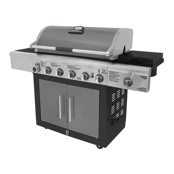
- Page 34 ® Brinkmann 6 Burner Gas Grill (Assembled)
-
Page 35: Rotisserie Warnings
ROTISSERIE WARNINGS: WARNING ELECTRICAL GROUNDING INSTRUCTIONS: This appliance (rotisserie motor) is equipped with a three-prong (grounding) plug for your protection against electrical shock hazard. It should be plugged directly into a properly grounded three-prong receptacle. DO NOT cut or remove the grounding prong from this plug. -
Page 36: Rotisserie Assembly Instructions
ROTISSERIE ASSEMBLY INSTRUCTIONS: Step 1 Open grill hood and remove cooking grills. Step 2 Attach rotisserie bracket A on the left hand side of the grill using two M6 x 10 mm bolts (black) and two M6 nuts. Step 3 Slide rotisserie motor onto the rotisserie bracket A. -
Page 37: Rotisserie Operating Instructions
ROTISSERIE OPERATING INSTRUCTIONS: WARNING ELECTRICAL GROUNDING INSTRUCTIONS: This appliance (rotisserie motor) is equipped with a three-prong (grounding) plug for your protection against electrical shock hazard. It should be plugged directly into a properly grounded three-prong receptacle. DO NOT cut or remove the grounding prong from this plug. - Page 38 IMPORTANTES ADVERTENCIAS DE SEGURIDAD ES NUESTRO DESEO QUE ARME Y UTILICE SU PARRILLA EN LA FORMA MÁS SEGURA POSIBLE. EL PROPÓSITO DE ESTE SÍMBOLO DE ALERTA DE SEGURIDAD ES QUE USTED PRESTE ATENCIÓN A LOS POSIBLES PELIGROS CUANDO ARME Y UTILICE SU PARRILLA.
- Page 39 PELIGRO a) NO guarde un cilindro de gas de propano líquido de reserva debajo o cerca de este artefacto. b) Nunca llene el cilindro más de 80%. c) Si la información en (a) y (b) no se sigue exactamente, se puede producir un incendio y causar lesiones o hasta la muerte.
-
Page 40: Advertencias Generales
ADVERTENCIAS GENERALES: ADVERTENCIA • Antes de usar la parrilla por primera vez, pruebe todas las conexiones en busca de fugas, incluso si compró la parrilla totalmente armada y cada vez que vuelva a cargar el tanque. Inspeccione el sello de caucho del tanque de propano en busca de daños. -
Page 41: Advertencias Generales De La Freidora
Si perdió o dañó el termómetro suministrado con esta freidora/ caldera, debe obtener un termómetro de repuesto antes de usar la freidora. Utilice solo el termómetro de repuesto N.° 072- 0012-0. Puede obtener este termómetro comunicándose con The Brinkmann Corporation al 1-800-527-0717. •... -
Page 42: Especificaciones E Instalación Del Cilindro (Tanque) De Gas Lp
• Evite golpear o impactar contra el artefacto para evitar salpicaduras o derrames de líquidos de cocción calientes. Tenga cuidado cuando camine o se pare cerca de la freidora, ya que el aceite derramado puede haber creado una superfi cie resbaladiza. - Page 43 ESPECIFICACIONES DEL CILINDRO (TANQUE) DE GAS LP: Cilindro de gas LP (no suministrado con esta parrilla) El cilindro de gas LP (propano líquido) específi camente diseñado para usarse con esta parrilla debe tener 12” (30.5 cm) de diámetro × 18” (45.7 cm) de alto y una capacidad de 20 lb (9.1 kg), con una válvula del cilindro Tipo 1 y un dispositivo de protección contra sobrecarga (OPD).
-
Page 44: Especifi Caciones E Instalación De La Manguera Y El Regulador
LP (propano). Para las parrillas dobles a combustible que pueden convertirse a gas natural, debe comprar un kit de conversión Brinkmann e instalarlo para usar con gas natural. Comuníquese con el Servicio de atención al cliente de Brinkmann llamando al 800-527-0717 para ver si su parrilla puede convertirse. -
Page 45: Pruebas De Detección De Fugas
REGULADOR Y MANGUERA: La parrilla viene equipada con un dispositivo de conexión Tipo 1 con las siguientes características: 1. El sistema no permitirá la circulación de gas desde el cilindro hasta que se establezca una conexión positiva a la válvula. Nota: La válvula del cilindro y todas las perillas de los quemadores de la parrilla deben estar cerradas antes de realizar o quitar cualquier conexión. - Page 46 PELIGRO Para prevenir los peligros vinculados con los incendios o explosiones: • NO fume ni permita que haya fuentes de ignición en la zona donde lleve a cabo una prueba de detección de fugas. • Realice la prueba en un área bien ventilada AL AIRE LIBRE, protegida contra el viento. •...
-
Page 47: Lista De Comprobación Previa Al Arranque
LISTA DE COMPROBACIÓN PREVIA AL ARRANQUE: PELIGRO Si no se siguen estos pasos, pueden ocurrir daños a la propiedad, lesiones corporales, quemaduras graves y la muerte. Estos pasos deben llevarse a cabo después de que la parrilla se armó y antes de cada uso. NO use esta parrilla hasta haber leído y entendido TODAS las advertencias y las instrucciones incluidas en este manual. - Page 48 Para apagar, gire cada perilla de control en sentido horario hasta que se trabe en la posición “APAGADO” . Esto no apaga el fl ujo de gas del cilindro. Nota: Si el quemador no se enciende o la llama es muy baja, consulte la sección “Solución de Problemas”...
-
Page 49: Funcionamiento De La Parrilla
Nota: Observe la altura de la llama una vez encendida: La llama debe ser de color azul/amarillo y debe ser de 1” a 2” cuando el quemador está en la posición “ALTO” . Consulte la sección del manual sobre el ajuste de los quemadores para regular la llama. FUNCIONAMIENTO DE LA PARRILLA: ADVERTENCIA •... -
Page 50: Apagado De La Parrilla
PARA MINIMIZAR LAS LLAMARADAS: • Quítele el exceso de grasa a la carne antes de cocinarla. • Cocine carnes con alto contenido de grasa (pollo o cerdo) con una llama baja o indirectamente. • Asegúrese de que la parrilla esté sobre una superfi cie nivelada y de que la grasa pueda escurrirse por la parrilla a través del orifi cio de drenaje en la parte inferior hasta el depósito o la batea para la grasa. -
Page 51: Utilizando Otras Funciones De La Parrilla
Sear-X agrega un adicional de 12,000 BTU para el ajuste alto de un solo quemador de precisión de un minuto, se combina con una rejilla de diamantes de alta resistencia, Brinkmann Sear-X le dará encerrado en sabor y marcas de la parrilla perfectas en todo momento. - Page 52 CÓMO DETERMINAR LA CANTIDAD ADECUADA DE ACEITE: (Para usar con recipientes de cocción que no tienen línea máxima de llenado). Nunca utilice un recipiente de cocción más grande que 7 cuartos o uno que no entre en la apertura del quemador de la freidora.
-
Page 53: Cuidado Y Mantenimiento Adecuados
CUIDADO Y MANTENIMIENTO ADECUADOS: ADVERTENCIA: Si usa un cepillo de cerdas para limpiar cualquiera de las superfi cies para cocinar, asegúrese de que no queden cerdas sueltas sobre dichas superfi cies antes de usar la parrilla, ya que las cerdas sueltas se pueden pegar a la comida. - Page 54 LIMPIEZA Y MANTENIMIENTO DE LOS QUEMADORES: • Mantenga el artefacto libre de materiales combustibles, gasolina, y otros líquidos y vapores infl amables. • Mantenga las aberturas de ventilación del gabinete del cilindro despejadas y libres de desechos. • Inspeccione visualmente las llamas de los quemadores para corroborar su correcto funcionamiento (vea el gráfi co ilustrativo en el apartado “Conjunto de los Quemadores/Mantenimiento”...
-
Page 55: Transporte Y Almacenamiento
AJUSTE DE LOS QUEMADORES: ADVERTENCIA • NO intente ajustar el obturador de aire de los quemadores hasta que la parrilla se haya enfriado durante aproximadamente 30 minutos. Si no cumple con esta indicación, puede sufrir quemaduras graves. • Las llamas normales deben ser de color azul claro con puntas amarillas, y deben ser de entre 1” y 2” cuando el quemador está... -
Page 56: Solución De Problemas
SOLUCIÓN DE PROBLEMAS: Para ver videos de montaje o solución de problemas, visítenos en: Problema Causa posible Prevención/Cuidado El quemador no enciende La válvula del tanque de gas LP está cerrada Cerciórese de que el regulador esté conectado al tanque de gas LP con fi rmeza;... - Page 57 Problema Causa posible Prevención/Cuidado La llama es amarilla o Es posible que el quemador nuevo contenga Encienda la parrilla durante 15 minutos en la posición “ALTO” con la anaranjada aceites residuales de la fabricación tapa cerrada Es posible que haya telarañas o nidos Limpie el conjunto de los quemadores y los tubos venturi de los de insectos en los tubos venturi de los quemadores...
-
Page 58: Sugerencias Para Cocinar Con La Parrilla
SUGERENCIAS PARA COCINAR CON LA PARRILLA: HIGIENE: • Siempre lávese las manos minuciosamente con jabón y agua caliente antes de manipular la comida y después de manipular carne vacuna o de pollo cruda, o mariscos/pescados. • Cuando use una fuente para transportar carne vacuna o de pollo cruda, o mariscos/pescado hasta la parrilla, asegúrese de lavar la fuente minuciosamente con jabón y agua caliente antes de colocar la comida cocida en dicha fuente, o use fuentes diferentes para los alimentos crudos y la comida cocida. -
Page 59: Instrucciones De Armado
INSTRUCCIONES DE ARMADO: LEA DETENIDAMENTE TODAS LAS ADVERTENCIAS DE SEGURIDAD E INSTRUCCIONES ANTES DE ARMAR Y USAR LA PARRILLA Verifi que que tiene todos los artículos indicados en la LISTA DE PARTES y en el CONTENIDO DE LA BOLSA DE PARTES antes de comenzar con el proceso de instalación. La bolsa de partes incluirá... - Page 60 RECOMENDAMOS QUE ESTA UNIDAD SEA ARMADA POR DOS PERSONAS Se necesitan las siguientes herramientas para armar esta Parrilla a Gas Brinkmann ® Select con 6 Quemadores: • Destornillador de Cabeza Phillips • Llave de Tuercas Hexagonales LISTA DE PARTES: Rejilla para Calentar...
- Page 61 PARA ENCONTRAR PARTES DE REEMPLAZO PARA SU PARRILLA, CUBIERTAS Y ACCESORIOS, FAVOR DE VISITARNOS AL (La prueba de compra se requiere.) Inspeccione el contenido de la caja para verifi car que todas las partes estén incluidas e intactas.
- Page 62 Elija un lugar adecuado y despejado para armar la parrilla y pídale a un Ruedilla Giratoria Ruedilla No Non Locking Non Swivel amigo que le ayude. Tienda cartón que No Traba Swivel Caster Giratoria Caster sobre el suelo para proteger el Locking Ruedilla Ruedilla No...
- Page 63 Paso 6 Alinear el soporte del sostenedor del tanque al montaje de la aguja del tanque utilizando bisagra y chaveta, como se ilustra. Paso 7 Bloquee las ruedas. Alinear Panel Lateral Panel Lateral los agujeros de clave en fondo Derecho del Carro Izquirda del Carro del lado carrito paneles con sus correspondientes pernos...
- Page 64 Paso 10 Use cuatro pernos M6 X 12 mm (negros) para fi jar la barra del Barra del Bloque del Tanque bloque del tanque a la base del carro y el apoyo superior del carro. Paso 11 Para fi jar las puertas al montaje Left Door Right Door del carro, inserte el pasador de...
- Page 65 Paso 13 Inserte los tres pernos de pre- adjunta del panel delantero de la mesa lateral izquierda en los tres orifi cios de la tabla del lado izquierdo, deslice hacia abajo y apriete los pernos. Paso 14 Inserte los tres pernos de pre- adjunta del panel frontal montaje freidora en los tres orifi cios de la asamblea freidora, deslice hacia...
- Page 66 Paso 15 Fije la mesa lateral izquierda al lateral izquierdo del montaje del armazón del carro. Coloque la mesa sobre los pernos previamente fi jados y deslícela hacia la parte trasera de la parrilla; luego ajuste los pernos fi rmemente. Ajuste el panel frontal de la mesa lateral al cuerpo de la parrilla con un perno M6 X 12 mm (negro).
- Page 67 Paso 17 Coloque la tapa del freidora al montaje de la freidora usando dos pasadores de la bisagra de la freidora y chavetas como se ilustra. Figura 1 Quemador Freidora Paso 18 Instale la freidora lateral (Figura 1). Conecte un M4 X 10 mm perno (plata) de la parte superior de la freidora lateral para asegurar en su lugar (Figura 2).
- Page 68 Paso 19 Inserte los tornillos preanexados en el ensamble de la válvula del quemador freidora a través de los orifi cios del panel frontal del quemador freidora, luego fi rmemente asiente la boquilla de la válvula dentro del venturi del quemador. Deslice el montaje de la válvula del quemador hacia abajo en los orifi cios del bisel de la perilla del...
- Page 69 Paso 21 Alinee el mango con los orifi cios para pernos en la cesta e inserte tres pernos M5 X 10 mm (plateado) y tuercas M5 (plateado) como se ilustra; luego ajuste con fi rmeza. Paso 22 Coloque la rejilla de la quemador freidora sobre la mesa de la quemador freidora.
- Page 70 Rejilla para Calentar Paso 25 Rejilla para Dorar Coloque las placas de distribución Rejillas para de calor y la placa de distribución Cocinar de calor de acero inoxidable del quemador para dorar en el nivel inferior del montaje del cuerpo de la parrilla, directamente sobre los quemadores.
- Page 71 ® Parrilla Brinkmann de 6 Quemadores a Gas (Armada)
-
Page 72: Advertencias Del Asador
ADVERTENCIAS DEL ASADOR: ADVERTENCIA INSTRUCCIONES PARA CONECTAR A TIERRA LOS ARTEFACTOS ELÉCTRICOS: Este artefacto (motor del asador estilo rotisserie) está equipado con un enchufe de tres clavijas (de puesta a tierra) para proteger al usuario contra el electrochoque. Este enchufe debe conectarse directamente a un receptáculo para tres clavijas conectado correctamente a tierra. -
Page 73: Instrucciones De Armado Del Asador
INSTRUCCIONES DE ARMADO DEL ASADOR: Paso 1 Abra la cubierta de la parrilla y quite las rejillas para cocinar. Paso 2 Instale el soporte A del asador en el lado izquierdo de la parrilla con dos pernos M6 x 10 mm (negros) y dos tuercas M6. -
Page 74: Funcionamiento Del Asador
INSTRUCCIONES DE FUNCIONAMIENTO DEL ASADOR: ADVERTENCIA INSTRUCCIONES PARA CONECTAR A TIERRA LOS ARTEFACTOS ELÉCTRICOS: Este artefacto (motor del asador estilo rotisserie) está equipado con un enchufe de tres clavijas (de puesta a tierra) para proteger al usuario contra el electrochoque. Este enchufe debe conectarse directamente a un receptáculo para tres clavijas conectado correctamente a tierra. - Page 75 This warranty extends to the original purchaser only and is not trans fer able or assignable to subsequent purchasers. The Brinkmann Corporation requires reasonable proof of purchase. Therefore, we strongly recommend that you retain your sales receipt or invoice. To obtain ®...