
Related Manuals for Sony DNW-A75 BETACAM SX


Summary of Contents for Sony DNW-A75 BETACAM SX
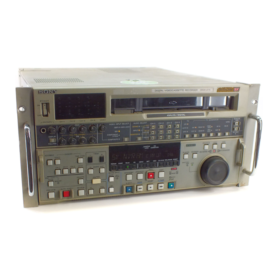
- Page 1 DIGITAL VIDEOCASSETTE RECORDER DNW-A75/A75P OPERATION MANUAL [English] 1st Edition (Revised 4)
- Page 2 WARNING For the customers in Europe This product with the CE marking complies with both the EMC Directive (89/336/EEC) and the Low Voltage Directive To prevent fire or shock hazard, do not (73/23/EEC) issued by the Commission of the European expose the unit to rain or moisture.
-
Page 3: Table Of Contents
Table of Contents 1-1 Features ................... 1-1 Chapter 1 1-2 Example System Configurations ........... 1-3 Overview 2-1 Control Panels ................. 2-1 Chapter 2 2-1-1 Upper Control Panel ............... 2-2 Location and Function of 2-1-2 Lower Control Panel ............... 2-7 Parts 2-1-3 Subsidiary Control Panel ............ - Page 4 Table of Contents 6-1 Overview ..................6-1 Chapter 6 6-2 Shot Mark Operation Menu ............6-2 Shot Mark Function 6-3 Shot Mark Operations ..............6-3 6-3-1 Reading Shot Marks .............. 6-3 6-3-2 Writing Shot Marks ............... 6-3 6-3-3 Shot Mark List Operations ............ 6-4 6-3-4 Cueing Up to Shot Marks ............
-
Page 5: Features
1-1 Features The DNW-A75/A75P is a digital videocassette High image quality, high audio quality, recorder, based on the Betacam SX format. high reliability This unit not only offers digital recording and playback, but can also play back tapes recorded in the Even with a low data rate, recording and playback with conventional analog Betacam format. - Page 6 1-1 Features Powerful editing functions Menu-based setup With two of these units together, you can carry out Initial settings for the unit’s operating condition, the automatic or manual editing, using either assemble or interfaces with connected equipment, and so forth can insert editing.
-
Page 7: Example System Configurations
1-2 Example System Configurations The following conceptual diagrams show examples of use in an outside broadcast van or local station and within a broadcasting station. • Operation in an outside broadcast van or local station Betacam SX camcorder Microphone system Digital (SDTI/SDI) Digital cassette Digital... -
Page 9: Location And Function Of Parts
2-1 Control Panels There are three control panels, as follows: • Upper control panel • Lower control panel • Subsidiary control panel Upper control panel (See page 2-2.) Subsidiary control panel (See page 2-16.) VI TC UB INTRP A IN DF LTC VITC 8F 4F 2F CONFI ON DOLBY A OUT... -
Page 10: Upper Control Panel
2-1 Control Panels 2-1-1 Upper Control Panel 4 VIDEO INPUT SELECT switch and indicators 1 POWER 2 Level meters switch 3 REC controls 5 Audio selection function selector switch and indicators 6 Audio signal selection buttons Cassette compartment POWER ANALOG / DIGITAL PHONES CH-1 CH-2... - Page 11 4 VIDEO INPUT SELECT switch and indicators 5 Audio selection function selector switch and This switch selects the video input signal in the indicators following sequence. Pressing this switch lights the MIXING indicator, SDTI n SDI n COMPONENT n COMPOSITE INPUT indicator and MONITOR indicator cyclically, and selects the function of the audio signal selection buttons.
- Page 12 2-1 Control Panels 6 Audio signal selection buttons However, when the video input signals selected with The function of these buttons depends on the setting of the VIDEO INPUT SELECT switch are SDTI, the the audio selection function selector switch as follows. audio input signals for all channels are also set to SDTI.
- Page 13 0 PHONES jack and control INT/EXT (internal/external) switch and indicators Connect stereo headphones with an impedance of 8 This switch selects the time code used: ohms, to monitor the sound during recording, playback INT: The time code produced by the internal time and editing.
- Page 14 2-1 Control Panels DF/NDF (drop-frame/non-drop-frame) switch and indicators In a 525/60 system, this switch selects the mode of advancing the time code generator and CTL counter. DF: Drop-frame mode. NDF: Non-drop-frame mode. The indicator corresponding to the selection lights. Note When the PRESET/REGEN switch is set to REGEN, since the time code generator is synchronized to the playback time code, this switch has no effect.
-
Page 15: Lower Control Panel
2-1-2 Lower Control Panel 1 Editing mode setting section 2 Monitor/menu/display setting section 3 Display section SHUTTLE CAPSTAN BETACAM SX LOCK CONDITION ASSEMBLE INSERT TRIM – VI TC UB A IN DF LTC VITC 8F 4F 2F CONFI ON VIDEO TIME CODE DOLBY A OUT... -
Page 16: Menu Button
2-1 Control Panels 5 MENU button 2 Monitor/menu/display setting section Use this button for setup menu operations. Pressing this button, turning it on, displays setup menus in the fluorescent display of the display section 3. Press the button once more to exit from the menu 1 PREREAD button display. -
Page 17: Display Section
9 TOTAL/REMAIN button 0 RESET button Press this button to switch between a TOTAL To reset a CTL, time code (TC) or user bit (UB) value indication or REMAIN (remaining) indication on the displayed in the fluorescent display, hold this button fluorescent display. - Page 18 2-1 Control Panels Time data display area 2 • DF (drop-frame) indicator: This lights when a This shows a TOTAL time indication or REMAIN displayed time code value is in drop-frame mode. (remaining) time indication according to the setting of •...
- Page 19 • 525, 625: The indicator showing the number of scan REC (recording) INHIBIT indicator This indicator is on or off according to the lines for the television standard selected using combination of the setting of the REC INHIBIT switch basic menu item 013 lights (NTSC: 525 scan on the subsidiary control panel and the record inhibit lines, field frequency 60 Hz;...
-
Page 20: Editing Control Section
2-1 Control Panels Hold down the IN, OUT, AUDIO IN, or AUDIO OUT 4 Editing control section button, and press one of these buttons. The + button advances the corresponding edit point by one frame, 1 DMC EDIT/FEED button and the – button sets it back by one frame. Pressing one of these buttons while holding down the 4 TRIM buttons 2 MEMORY indicator... -
Page 21: Standby Button
ENTRY button 6 Tape transport control section Use this for setting edit points and so forth. • To set a video IN point or OUT point: Hold down the IN button or OUT button, and press this button. 1 STANDBY button •... -
Page 22: Search Control Section
2-1 Control Panels 3 REC (record) button 7 PLAY button To start recording, press this button together with the To start playback, press this button, turning it on. PLAY button, turning it on. To operate in capstan override mode Monitoring in E-E mode Hold down this button, and turn the search dial. - Page 23 2 JOG button Playback modes using the search dial To use the search dial for playback in jog mode, press Playback mode Operations and functions this button, turning it on. Shuttle Press the SHUTTLE button or the search dial so that the SHUTTLE button lights, then turn the search dial.
-
Page 24: Subsidiary Control Panel
2-1 Control Panels 2-1-3 Subsidiary Control Panel Pull out the lower control panel to reveal the subsidiary control panel. 1 CONTROL PANEL switch 2 CHARACTER switch 3 DOLBY NR switch 4 OUT REF switch !∞ CAPSTAN LOCK switch !¢ KEY INHIBIT switch 5 PROCESS CONTROL switch !£... - Page 25 4 OUT REF (reference) switch 7 CHROMA (chrominance) knob and PRESET/ This switch selects the reference signal for this unit MANUAL switch depending on the combination of the setting of The switch makes the selection described immediately extended menu item 309 and the operating state of the below.
- Page 26 2-1 Control Panels 0 CHROMA (chrominance) PHASE knob and • For assemble editing, there may be a color PRESET/MANUAL switch framing discontinuity at edit points. The switch makes the selection described immediately During playback of a tape recorded with a below.
-
Page 27: Connector Panel
2-2 Connector Panel 3 Digital input/output section (See page 2-21.) 4 Time code input/output section and audio monitor signal output section Cooling fan (See page 2-21.) 1 Analog audio input/output section (See page 2-20.) 5 Digital audio input/output section (See page 2-22.) 2 Analog video input/output Cooling fan section (See page 2-20.) -
Page 28: Connector Panel
2-2 Connector Panel 1 Analog audio input/output section 2 Analog video input/output section 1 AUDIO INPUT CH1 to CH4 connectors 1 REF. VIDEO INPUT connectors and 75 Ω termination switch 2 COMPOSITE VIDEO INPUT connectors 2 AUDIO INPUT CH1 to CH4 LEVEL switches and 75 Ω... - Page 29 5 COMPONENT VIDEO OUTPUT connectors 4 Time code input/output section and (BNC type) audio monitor signal output section These output analog component video signals (Y/R–Y/ B–Y). 1 TIME CODE IN connector 3 Digital input/output section 2 TIME CODE OUT connector TIME CODE 1 SDI INPUT connectors SDTI...
- Page 30 2-2 Connector Panel 5 Digital audio input/output section 1 AUDIO INPUT (AES/EBU) connectors (BNC 1 AUDIO INPUT (AES/EBU) connectors type) Input up to two sets (4 channels: channels 1/2 and 3/4) AUDIO INPUT(AES/EBU) of AES/EBU format digital audio signals. CH1/2 CH3/4 2 AUDIO OUTPUT (AES/EBU) connectors (BNC type)
- Page 31 6 REMOTE 2 PARALLEL I/O (50P) connector (D-sub 50-pin) Connect remote control signals from an external device. For details, refer to the Installation Manual. 7 Power supply section 1 AC IN connector 2 BREAKER button Use the optional power cord to connect this to an AC outlet.
-
Page 33: Connections To External Devices
3-1 Connections to External Devices 3-1-1 Connections to Digital Devices The following example shows the connections with another DNW-A75/A75P as a player and a DVR-2100 D1 component digital VTR as recorder. DNW-A75/A75P (Player) SDI OUTPUT REMOTE-IN(9P) DNW-A75/A75P SDI INPUT SDI OUTPUT 3 BVM-1454 Series SDI OUTPUT 2 Video Monitor... -
Page 34: Connections To Analog Devices
3-1 Connections to External Devices 3-1-2 Connections to Analog Devices The following example shows the connections with a Betacam SP VTR, 1-inch VTR, D2 VTR, and so forth for recording analog audio and video signals. Video monitor 75 Ω termination switch: set to OFF when using an analog COMPONENT/ composite video signal bridge... -
Page 35: Reference Signals For Video Output And Servo System
3-2 Reference Signals for Video Output and Servo System This section describes how reference signals for the The output from the internal reference video signal video output signals and servo system are selected. generator is supplied to the output video signal and servo circuits as a reference signal. -
Page 36: Reference Signal For The Servo System
3-2 Reference Signals for Video Output and Servo System 3-2-2 Reference Signal for the Servo System The VTR automatically selects either the input video system. Which of the two signals is selected depends signal or the output from the internal reference video on the operational status of the VTR, as shown in the signal generator as the reference signal for the servo following flowchart. -
Page 37: Connecting Reference Signals
3-2-3 Connecting Reference Signals Connect reference signals as shown below, according to the way in which the unit is to be used. • Connections for recording from a switcher or signal generator Reference signal Switcher or signal generator REF. VIDEO INPUT SDI INPUT 75 Ω... - Page 38 3-2 Reference Signals for Video Output and Servo System • Connections for playback Reference signal Serial monitor REF. VIDEO SDI OUTPUT INPUT 75 Ω termination switch: ON DNW-A75/A75P Chapter 3 Preparations...
-
Page 39: Setup
3-3 Setup The principal setup operations before operating this unit can be carried out using setup menus. The setup menus of this unit comprise a basic menu and an extended menu. The contents of these menus are as follows. Basic menu: •... -
Page 40: Superimposed Character Information
3-4 Superimposed Character Information 3-4 Superimposed Character Information When the CHARACTER switch on the subsidiary Adjusting the character display control panel is set to ON, the video signal output from the COMPOSITE VIDEO OUTPUT 3 (SUPER) You can adjust the position, size and type of the connector or the SDI OUTPUT 3 (SUPER) connector superimposed characters using the basic menu. - Page 41 2 Drop frame mode for time code reader (for 525 Display Operation mode mode only) Block A Block B “.”: Drop frame mode UNTHREAD Cassette is not loaded. “:”: Non-drop-frame mode STANDBY OFF Standby off mode 3 Drop frame mode for time code generator (for T.RELEASE Tape tension released 525 mode only)
-
Page 42: Cassettes
3-5 Cassettes 3-5 Cassettes Turn the POWER switch on. 3-5-1 Cassette Types Check the following points, before inserting the This unit uses a -inch tape width for both recording cassette in the orientation shown in the figure. and playback. You can use Betacam SX cassettes, •... -
Page 43: Preventing Accidental Erasure Of Recordings
3-5-3 Preventing Accidental Erasure of Recordings To prevent a tape from being inadvertently erased, press in the red erase-protect plug on the cassette. Large cassette Small cassette Press in the red erase-protect plug. (“ON”) Return this plug to its original position to enable recording on the tape again. -
Page 45: Recording And Playback
4-1 Recording This section describes video and audio recording on the unit. 4-1-1 Preparations for Recording For details of the settings of each of the switches, refer to Switch settings the pages indicated in parenthesis. Before beginning recording, make any necessary switch settings. - Page 46 4-1 Recording Adjusting the audio recording levels To use the emphasis function When carrying out audio recording at a To add emphasis to the analog input audio signal or reference level analog playback audio signal, set the extended menu Leave the REC controls pressed in. The audio signals item 817 to ON.
- Page 47 Setting an initial time code value Setting the time code value to the real time Use the following procedure. With the switches in the time code setting section set as follows, carry out the procedure under the heading above, “To set an initial time code value”. In steps 4 Time data display area 2 and 5, set the value slightly after the current time, then RESET button...
- Page 48 4-1 Recording Set the switches as follows: To synchronize the internal time code INT/EXT switch: EXT generator to an external signal PRESET/REGEN switch: REGEN VITC switch: ON (when recording VITC) Use this method to synchronize the time code TC switch: LTC or VITC according as you are generators of a number of VTRs, or to record the synchronizing to LTC or VITC (If set to playback time code signal from an external VTR...
-
Page 49: Recording Procedure
4-1-3 Recording Procedure To record, use the following procedure. Insert a cassette. For details, see the section “Inserting a cassette” (page 3-10). Hold down the REC button, and press the PLAY button. Recording starts, the servo locks, and the SERVO indicator lights. -
Page 50: Playback
4-2 Playback 4-2 Playback This section describes playback of video and audio. 4-2-1 Preparations for Playback For details of the settings of each of the switches, refer to Switch settings the pages indicated in parenthesis. Before beginning playback, make any necessary switch settings. -
Page 51: Playback/Feed Play Procedures
Time data selection 4-2-2 Playback/Feed Play Procedures Displayed time data Use the CTL/TC/UB button to select one of CTL This section describes the following types of playback (control), time code, and user bit values. When you which the unit can carry out: select time code, the data displayed is determined by •... - Page 52 4-2 Playback Normal playback Playback in jog mode First insert a cassette. In jog mode, you can control the speed of playback by the speed of turning the search dial. The playback For details of how to insert a cassette, see Section 3-5-2, speed range is ±1 times normal speed.
- Page 53 To alternate between normal-speed playback Playback in shuttle mode and shuttle mode playback Set the search dial to the position corresponding to the In shuttle mode, you can control the speed of playback desired shuttle playback speed, then switch between by the angular position of the search dial.
- Page 54 4-2 Playback To alternate between normal-speed playback Carrying out playback in feed mode and variable mode playback Set the search dial to the position corresponding to the When using a Betacam SX tape, you can use feed desired variable playback speed, then switch between mode to play back at any speed from 0.1 to 2 times normal-speed playback and variable playback by normal.
-
Page 55: Dynamic Motion Control (Dmc) Playback
4-2-3 Dynamic Motion Control (DMC) Playback For example, during a live broadcast of a sporting Overview event you can set the start and end points of highlights while recording, and then provide immediate DMC DMC playback allows you to vary the playback speed playback of those highlights. - Page 56 4-2 Playback Holding down the DMC EDIT/FEED button, turn Executing DMC Playback the search dial, to set the initial speed at the playback start point. There are two methods of starting DMC playback. The speed you set appears in the time counter. •...
- Page 57 Starting playback immediately after preroll Press the PREVIEW button. The PREVIEW button lights, and after preroll, DMC playback is carried out for the section from the speed variation start point, then playback continues at normal speed from the speed variation end point. Stopping the tape during DMC playback Press the STOP button.
-
Page 59: Automatic Editing
5-1 Automatic Editing This section describes how to carry out automatic Sequence of editing operations editing with this unit and another VTR connected to the REMOTE1-IN(9P) connector. The following flowchart outlines the sequence of operations in automatic editing with two VTRs. 5-1-1 Overview Selecting the editing mode (page 5-3) Editing mode... -
Page 60: Switch Settings
5-1 Automatic Editing 5-1-2 Switch Settings Before beginning editing, set the switches as follows. Recorder settings VIDEO INPUT SELECT switch (see page 2-3) : Audio selection function selector switch select the input video signal (see page 2-3) : select the input audio signal REMOTE1(9P)/2(50P) buttons (see page 2-6) : 9 indicator off POWER switch: ON... -
Page 61: Selecting The Editing Mode
Press the RECORDER button or PLAYER button 5-1-3 Selecting the Editing Mode to select the VTR on which you will set the edit point. To select the editing mode Select assemble editing or insert editing. The button which you have pressed lights. Turn the search dial in jog or shuttle mode, and INSERT buttons position the tape at the required edit point. - Page 62 5-1 Automatic Editing Note Setting split edit points During split editing, if you set six or more edit points for the recorder and player, the DELETE button starts In split editing, you can set the edit points for audio to flash, to indicate that such a setup is impossible. and video independently.
- Page 63 When the audio IN point is not set for insert To display the duration of an edit editing of audio only As long as the audio OUT point is set, the VTR is You can display the duration between two edit points ready for preview or editing.
-
Page 64: Modifying And Deleting Edit Points
5-1 Automatic Editing Deleting an edit point 5-1-5 Modifying and Deleting Edit Points To delete an edit point, use the following procedure. You can use the same procedure whether or not the If the edit points are not set correctly, for example if an DELETE button is flashing. -
Page 65: Cue-Up To Edit Points And Preroll
5-1-6 Cue-up to Edit Points and 5-1-7 Preview Preroll When you have set the edit points, the PREVIEW button flashes, indicating that you can carry out a To preroll to an edit IN point or cue up to any edit preview. -
Page 66: Carrying Out Automatic Editing
5-1 Automatic Editing • From the OUT point to the postroll point, you can Monitor output monitor the playback from the recorder. During a preview, on a monitor connected to the The following figure illustrates this. recorder you can monitor the following video and audio. - Page 67 The following figure illustrates this. IN point OUT point Playback Playback E-E mode (recorder) (recorder) (player) OUT button In CONFI mode, you can monitor the video and audio ENTRY button signals actually recorded. You can use CONFI head playback for the whole edit operation from the preroll REVIEW button point to the postroll point, including the section AUTO EDIT button...
-
Page 68: Dmc Editing
5-2 DMC Editing 5-1 Automatic Editing When the player is a playing back in Betacam SX format, by controlling the player playback speed from the recorder you can achieve variable speed editing. 5-2-1 Overview of DMC Editing Conditions for DMC editing Tape movement during DMC editing DMC editing can be used for insert or assemble The following figure illustrates how the tapes move on... -
Page 69: Carrying Out Dmc Editing
When the initial speed setting is complete, release 5-2-2 Carrying Out DMC Editing the DMC EDIT/FEED button. Press the PREVIEW button. Setting the edit points and player speed The tape is prerolled and then the recorder starts Use the following procedure. operating at normal speed and the player at the set initial speed. -
Page 70: Special Automatic Editing Methods
5-3 Special Automatic Editing Methods 5-3 Special Automatic Editing Methods This section describes the following automatic editing 5-3-2 Continuous Editing methods: • Quick editing After an automatic editing operation, the recorder • Continuous editing automatically returns to the OUT point. For the •... -
Page 71: Standalone Editing
At the editing end point (the recorder OUT point), 5-3-3 Standalone Editing press the PLAY button. This refers to editing using as the player an external Editing ends, and the recorder continues with device which cannot be controlled remotely through playback. - Page 72 5-3 Special Automatic Editing Methods Notes • In preread editing, if an input video signal is used as the reference signal for the output video signal, this forms a feedback loop. To prevent the occurrence of feedback, set the OUT REF switch on the subsidiary control panel to REF, and set item 309 in the setup menus to “1”...
-
Page 73: Overview
6-1 Overview This unit can record shot marks or use shot marks indications at desired points on a tape which enable recorded with Betacam SX camcorders.Shot marks are faster cueing. Types of shot mark This unit supports the following three types of shot post marks, treating them as varieties of shot marks. -
Page 74: Shot Mark Operation Menu
6-2 Shot Mark Operation Menu This section describes the settings in the shot mark Details of the shot mark operation menu operation menu. The shot mark operation menu comprises four items, G01 to G04. The detailed contents appear in the Displaying the shot mark operation menu following table. -
Page 75: Shot Mark Operations
6-3 Shot Mark Operations This section describes the operations concerning Reading shot marks from more than one reading and writing shot marks. Note that the cassette following operations cannot be carried out by remote control. After changing the cassettes, carry out the reading operation again. -
Page 76: Shot Mark List Operations
6-3 Shot Mark Operations To write in crash recording or assemble 6-3-3 Shot Mark List Operations editing At the position you wish to write the mark, hold down the ENTRY button, and press the MARK button. Displaying the shot mark list Hold down the ENTRY button and press the LIST button. - Page 77 You can also use the following procedure. Selecting a shot mark With the shot mark list displayed, hold down the Turn the search dial to align the asterisk cursor with STOP button, and press the SET button. the desired shot mark. You can now select the shot mark types.
-
Page 78: Cueing Up To Shot Marks
6-3 Shot Mark Operations To delete the entire list 6-3-4 Cueing Up to Shot Marks Hold down the DELETE button and press the LIST button. This deletes all shot marks from the list. This does not Cueing up to a selected shot mark erase marks from the tape. -
Page 79: Reading In Shot Data
Displaying the shot data on the shot mark 6-3-5 Reading in Shot Data list When there is shot data (time, device, and other Turn the search dial to position the cursor on a information about the shooting) written on the tape, separator in the shot mark list. -
Page 80: Sorting Shot Marks
6-3 Shot Mark Operations 6-3-6 Sorting Shot Marks Based on shot data recorded on the tape, you can With the shot mark list displayed, hold down the separate the shot marks by cassette, and sort them in STOP button and press the SET button. timecode sequence. -
Page 81: Menu System Configuration
7-1 Menu System Configuration The menu system of this unit comprises the basic For detailed information about menu operation relating to the hours meter, see Section 8-4 “Digital Hours Meter” menu and extended menu. (page 8-3). • Basic menu This menu is used to make settings relating, for •... - Page 82 7-2 Basic Menu Item number Item name Settings DISPLAY INFORMATION Determines the kind of character information to be output from the COMPOSITE SELECT VIDEO OUTPUT 3 (SUPER) connector and the SDI OUTPUT 3 (SUPER) connector when the CHARACTER switch on the subsidiary control panel is set to T&STA : Time data display information and the unit’s status.
- Page 83 Item number Item name Settings RECALL BANK 1 Set to ON to recall menu settings from menu bank 1. RECALL BANK 2 Set to ON to recall menu settings from menu bank 2. RECALL BANK 3 Set to ON to recall menu settings from menu bank 3. RECALL BANK 4 Set to ON to recall menu settings from menu bank 4.
-
Page 84: Basic Menu Operations
7-2 Basic Menu To display the full item name 7-2-2 Basic Menu Operations Hold down the F FWD button. This section describes the basic menu displays and how to change the settings. For information about how to use item 013, see the section “Switching between 525/625 line systems (menu item 013)”... - Page 85 Changing the currently displayed menu Changing a menu item setting value item To change the setting value of the currently displayed menu item, use the following procedure. VAR button JOG button SHUTTLE button Search dial Holding down the SHUTTLE button or JOG Turn the search dial.
- Page 86 7-2 Basic Menu Note on using the DNW-A75P in 525 mode Resetting the menu settings to their If you switch to 525 mode, Betacam and Betacam SP factory default values (menu item B20) format can be played back in 525 mode, but only in the simple playback mode.
- Page 87 Press the SET button. Press the SET button. The displays change as follows. The displays change as follows. Time data display Time data display Monitor screen Monitor screen 525/625 SYSTEM SELECT 525/625 SYSTEM SELECT If the 525/625 setting Turn off/on POWER!! is changed, turn power off and on! To abandon the 525/625 setting operation...
- Page 88 7-2 Basic Menu Menu bank operations (menu items B01 to B14) This unit allows four different complete sets of menu settings to be saved in what are termed “menu banks” numbered 1 to 4. Saved sets of menu settings can be recalled for use as required.
-
Page 89: Extended Menu
7-3 Extended Menu 7-3-1 Items in the Extended Menu The extended menu contains the following items. In the “Settings” column of the table, the factory default settings are indicated by an enclosing box. Menu items in the 100s, relating to the control panels Item number Item name Settings SELECTION FOR... - Page 90 7-3 Extended Menu Menu items in the 100s, relating to the control panels (Continued) Item number Item name Settings REC INHIBIT LAMP Select whether or not to flash the REC INHIBIT indicator when the REC INHIBIT FLASHING switch on the subsidiary control panel is set to OFF and the REC inhibit plug on the cassette is pressed in.
- Page 91 Menu items in the 100s, relating to the control panels (Continued) Item number Item name Settings KEY INHIBIT SWITCH Select which switches and buttons can be operated when the KEY INHIBIT EFFECTIVE AREA switch on the subsidiary control panel is set to ON. The following sub-items control different sets of switches and buttons independently.
- Page 92 7-3 Extended Menu Menu items in the 300s, relating to editing operations Item number Item name Settings VAR SPEED RANGE FOR Select the playback speed range when carrying out playback in variable mode SYNCHRONIZATION from a remote control unit connected to the REMOTE-1 IN (9P) connector or REMOTE-1 OUT (9P) connector.
- Page 93 Menu items in the 300s, relating to editing operations (Continued) Item number Item name Settings SERVO/AV REFERENCE Select the servo reference signal. AUTO1 : During recording, an analog component/composite or digital input video signal is used as the servo reference signal. During playback, the signal selected by the OUT REF switch on the subsidiary control panel is used as the servo reference signal.
- Page 94 7-3 Extended Menu Menu items in the 300s, relating to editing operations (Continued) Item number Item name Settings EDIT RETRY For two-VTR editing, set when this unit is used as the recorder. Selects the operation if the recorder was not synchronized in time. OFF: Editing is not carried out, and the unit stops.
- Page 95 Menu items in the 500s, relating to tape protection Item number Item name Settings Select the time delay from the tape transport stopping (either the “STOP mode” STILL TIMER or the still playback mode in search mode) until the unit automatically switches to the tape protection mode, in order to protect the video heads and the tape.
- Page 96 7-3 Extended Menu Menu items in the 600s, relating to the time code generator (Continued) Item number Item name Settings VITC POSITION SEL-2 In 525 mode Select a line to insert the VITC in. 12H ... 18H ... 20H: Select any line from 12 to 20. Note You can insert the VITC signal in two places.
- Page 97 Menu items in the 600s, relating to the time code generator (Continued) Item number Item name Settings PHASE CORRECTION Select whether or not to carry out phase correction control on the LTC generated by the time code generator. OFF : No control. ON: Carry out control.
- Page 98 7-3 Extended Menu Menu items in the 700s, relating to video control Item number Item name Settings SELECTION OF VIDEO/ An EE video signal is output delayed with respect to the video input signal by the SYNC DELAY time for video circuit processing. With this item, select whether or not to delay the sync signal attached to the output video signal by an amount corresponding to the delay.
- Page 99 Menu items in the 700s, relating to video control (Continued) Item number Item name Settings VERTICAL BLANKING V When the “Y-add” function is operative, when the playback signal is an odd field SHIFT and the reference signal is an even field, the playback signal is shifted by 1H (1 line) to suppress the vertical movement of the playback picture.
- Page 100 7-3 Extended Menu Menu items in the 700s, relating to video control (Continued) Item number Item name Settings VIDEO PROCESS ON When the CAPSTAN LOCK switch on the subsidiary control panel or menu item CAP LOCK 2FIELD 106 is set to 2FLD for 2-field playback, select whether or not to carry out a “picture shift”.
- Page 101 Menu items in the 700s, relating to video control (Continued) (Items 715 to 721: Settings for controlling the video processing system according to the menu settings.) Item number Item name Settings VIDEO GAIN CONTROL Adjust the video output level. Default value: 800H CHROMA GAIN Adjust the chroma output level.
- Page 102 7-3 Extended Menu Menu items in the 700s, relating to video control (Continued) Item number Item name Settings H BLANKING WIDTH Select the horizontal blanking width of a video output signal. NARROW : Digital blanking (narrow) WIDE: Analog blanking (wide) When analog blanking is selected, the horizontal blanking width complies with RS170A, and normally the blanking is widened and the image becomes narrower.
- Page 103 Menu items in the 800s, relating to audio control (Continued) Settings Item number Item name AUDIO OUTPUT PHASE Select the output timing of a digital audio playback signal (SDI and AES/EBU only). The reference position corresponds to a setting of 80H; when the setting is less than 80H, the output timing is advanced, and when it is higher than 80H, the output timing is delayed.
- Page 104 7-3 Extended Menu Menu items in the 900s, relating to digital processing Item number Item name Settings FREEZE MODE Select the freeze mode and timing. FIELD : Freeze a video field. Field may be odd or even, according to the timing. FLD1: Freeze an odd field.
-
Page 105: Extended Menu Operations
7-3-2 Extended Menu Operations In the extended menu, you can carry out the same operations as in the basic menu. For details of basic menu operation, see Section 7-2-2, “Basic Menu Operations” (page 7-4). Note To access the extended menu, a setting on the internal SS-83 board is required. -
Page 107: Removing A Cassette When Tape Slack Occurs
8-2 Head Cleaning To clean the video heads and audio heads, always use Insert the cleaning cassette. the special-purpose Sony BCT-5CLN cleaning cassette. Press the EJECT button and PLAY button Follow the instructions with the cleaning cassette simultaneously. -
Page 108: Moisture Condensation
8-3 Moisture Condensation 8-4 Moisture Condensation When the unit is suddenly moved from a cold to a If this happens, the drum and capstan motors stop and warm location, or used in a very humid place, moisture the cassette is automatically ejected. Then, the durm from the air can condense on the head-drum. -
Page 109: Digital Hours Meter
8-4 Digital Hours Meter The hours meter can display eight items of Displaying the hours meter information, in corresponding display modes, about the operational history of the unit. Use it as a guide in scheduling periodic maintenance. Search dial Display modes of the hours meter H01: OPERATION mode Displays the total number of hours the unit has been powered on in units of 1 hour. -
Page 111: Specifications
Specifications Servo lock time 0.5 seconds or less (from standby General Load/unload time 6 seconds or less Recording format Betacam SX Recommended tapes Power requirements Betacam SX cassette (S, L): BCT- 100 to 240 VAC, 50/60 Hz 12SX/22SX/32SX/60SX, BCT- Power consumption 64SXL/94SXL/124SXL/184SXL 215 VA Betacam SP cassette (S, L) - Page 112 Specifications Analog composite input to analog composite Digital audio system output Bandwidth (Y) DNW-A75: 0 to 4.5 MHz Digital audio (CH-1 to CH-4) signal format +0.5 dB/ –3.0 dB Sampling frequency DNW-A75P: 0 to 5.5 MHz 48 kHz (synchronized with video) +0.5 dB/ –3.0 dB Quantization 16 bits/ sample...
- Page 113 Analog Betacam playback (DNW-A75) Video Metal tape Oxide tape Bandwidth 30 Hz to 4.5 MHz +0.5 dB/ –4.0 dB 30 Hz to 4.1 MHz +0.5 dB/ –6.0 dB R–Y/ B–Y 30 Hz to 1.5 MHz +0.5 dB/–3.0dB 30 Hz to 1.5 MHz +0.5 dB/–3.0 dB S/N ratio 51 dB or more 48 dB or more...
- Page 114 Specifications Processor adjustment range Output connectors Video level ±3 dB/ –∞ to +3 dB selectable SDI OUTPUT Chroma level ±3 dB/ –∞ to +3 dB selectable BNC (3 including 1 for character Setup level (DNW-A75) superimpose) ±30 IRE serial digital (270 Mbits/ s) Black level (DNW-A75P) SMPTE 259 M/CCIR 656-III SDTI OUTPUT...
- Page 115 Remote connectors CONTROL PANEL 29-pin, female REMOTE1-IN(9P) D-sub 9-pin, female REMOTE1-OUT(9P) D-sub 9-pin, female RS-232C D-sub 9-pin, male VIDEO CONTROL D-sub 15-pin, male (for optional BVR-50/50P) REMOTE 2 PARALLEL I/O (50P) 50-pin, female Accessories supplied RCC-5G 9-pin remote control cable (1) PSW 4 ×...
-
Page 117: Index
Index Continuous editing 5-12 CONTROL PANEL connector 2-22 AC IN connector 2-23 Ground terminal 2-23 CONTROL PANEL switch 2-16 AES/EBU digital audio 1-1 Control panels 2-1 ALARM indicator 2-11 CTL/TC/UB button 2-8 Analog Head Cleaning 8-1 device connection 3-2 Head configuration 1-1 video/audio signal 1-1 HOLD button 2-8 DELETE button 2-12... - Page 118 Index RESET button 2-8 REVIEW button 2-12 PB button 2-8 Upper control panel 2-2 REW button 2-13 PB controls 2-2 User bit values 4-2 RS-232C connector 2-22 PB.EE button 2-8 RS-232C indicator 2-2 PHONES jack and control 2-2 PLAY button 2-13 VAR button 2-14 Playback Variable mode 4-9...
- Page 119 The material contained in this manual consists of information that is the property of Sony Corporation and is intended solely for use by the purchasers of the equipment described in this manual. Sony Corporation expressly prohibits the duplication of any...
- Page 120 Printed in Japan DNW-A75/A75P Sony Corporation 1999.09.13 (SYL, © 1998 Broadcasting & Professional Systems Company 3-864-527-05(1)