Table of Contents
Advertisement
Quick Links
Advertisement
Table of Contents

Related Manuals for Datavideo VS-100


Summary of Contents for Datavideo VS-100
- Page 1 Sampling Video Scope VS-100 Instruction Manual www.datavideo-tek.com...
-
Page 2: Table Of Contents
Supported SDI / HD-SDI Input Video Formats ......... 7 Example Set Up .................. 8 Connections & Controls ................9 Front & Rear Panels ................9 VS-100 Output Display ..............10 Menu Control and Options ..............11 NEXT MODE ..................11 VIDEO DISPLAY................11 TOOLS ..................... - Page 3 Datavideo Technologies will try to give correct, complete and suitable information. However, Datavideo Technologies cannot exclude that some information in this manual, from time to time, may not be correct or may be incomplete. This manual may contain typing errors, omissions or incorrect information.
-
Page 4: Warnings And Precautions
AC adapter. If you are not sure of the type of power available, consult your Datavideo dealer or your local power company. Do not allow anything to rest on the power cord. Do not locate this unit where the power cord will be walked on, rolled over, or otherwise stressed. -
Page 5: Warranty
Drives are only covered for the first 10,000 hours, or 1 year (whichever comes first). Any second year warranty claims must be made to your local Datavideo office or one of its authorized Distributors before the extended warranty expires. -
Page 6: Packing List
Its small size and DC voltage input means that it can be a go-anywhere engineering tool when paired with a HD / SD monitor like the Datavideo TLM-700HD or a rack based studio tool when paired with a TLM-702HD monitor. -
Page 7: Features
Features Rugged and compact single unit that requires only an HD-SDI or HDMI monitor Menu choice of Vectorscope, Histogram, Waveform and Parade displays as well as clean Video Display output (SDI to HDMI conversion) SDI / HD-SDI input ... -
Page 8: Example Set Up
Example Set Up... -
Page 9: Connections & Controls
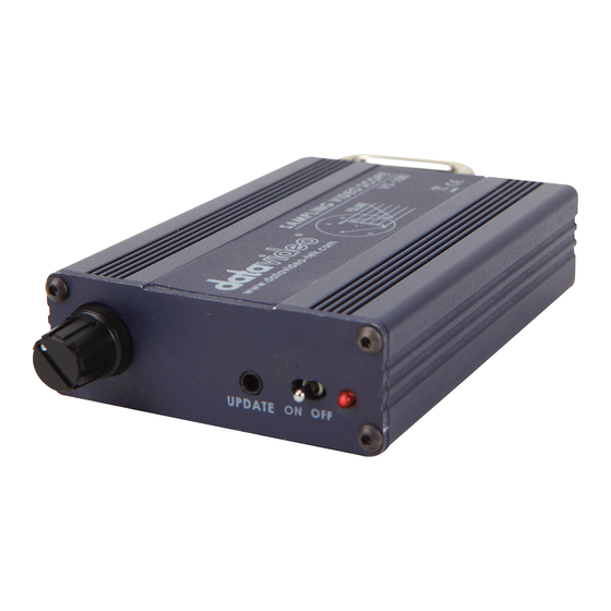
Connections & Controls Front & Rear Panels Menu dial and push to select button 3.5mm jack socket for audio monitoring Power ON / OFF switch with LED DC 12V / 0.2 A (4W) input connector HDMI output SDI / HD-SDI output / clean loop through SDI / HD-SDI input... -
Page 10: Vs-100 Output Display
VS-100 Output Display... -
Page 11: Menu Control And Options
Menu Control and Options The VS-100 is a menu driven unit. The menu is viewed as part of the output display when it has been connected to a HDMI / SDI monitor (see page 9). The menu options are scrolled by turning the Menu Dial to the left or right (See item 1 on page 8). -
Page 12: Tools
X DELAY TRACE MEMORY This option allows the current VS-100 scope trace to be saved, recalled or cleared within the unit’s memory. A saved or recalled trace will be displayed in green sample points and the live or current signals will be displayed in white sample points. -
Page 13: Zoom (Waveform Tools)
AUDIO VOLUME Audio embedded into the SDI / HD-SDI signal can be monitored by plugging headphones into the 3.5mm jack socket on the VS-100 front panel. Using the AUDIO VOLUME option, the Menu Dial can be used to increase or reduce the volume at the connected headphones, so it is monitored at a comfortable level. -
Page 14: Configuration
CONFIGURATION This option in the VS-100 Main Menu allows set up of Video Thumbnail, SDI loopthrough, Capture setting and confirmation of the VS-100 firmware revision. VIDEO THUMBNAIL Allows the option to switch the video thumbnail on the scope display between 4x3 (4:3) or 16x9 (16:9) aspect ratio when working with Standard Definition inputs. -
Page 15: Vs-100 Quick Start Guide
Turn on any set lights and ensure any coloured filters are removed. We want an evenly lit white reference card or background with only true white light. Select VECTORSCOPE mode on the VS-100 using the NEXT MODE option. Use the camera’s auto white balance feature to white balance against the solid white background or reference white card. -
Page 16: Luminance Adjustment (Histogram)
Once the first camera is correctly calibrated select TOOLS> TRACE MEMORY> SAVE TRACE to save the calibrated matrix levels from the first camera. Now connect VS-100 to the second camera on the set. Adjust the white and black balance on the next camera as described earlier. -
Page 17: Luminance Adjustment (Waveform Monitor)
Once the first camera is correctly calibrated select TOOLS> TRACE MEMORY> SAVE TRACE to save the calibrated matrix levels from the first camera. Now connect VS-100 to the second camera on the set. Adjust the white and black balance on the next camera as described earlier. -
Page 18: Colour /Hue Adjustment (Parade Rgb / Ycbcr)
Once the first camera is correctly set for colour select TOOLS> TRACE MEMORY> SAVE TRACE to save the current parade trace from the first camera. Now connect VS-100 to the second camera on the set. Adjust the white, black balance and luminance on the next camera as described earlier. -
Page 19: Camera Output After Adjustments (Vectorscope)
Under the same on set lighting conditions aim the camera at a colour reference chart (such as DSC labs’ Chroma Du Monde). Select VECTORSCOPE mode on the VS-100 using the NEXT MODE option. Now, the VECTORSCOPE displays the analyzed colour components. -
Page 20: Vs-100 Advanced Application
VS-100 Advanced Application RGB PARADE and White Balance Adjustment Select PARADE mode on the VS-100 using the NEXT MODE option. Then point the camera at the white background or white reference card. When the white balance is correctly adjusted, The RGB traces should be flat, balanced, and parallel to one another in a straight line. -
Page 21: Camera Noise
Camera Noise Adjust the IRIS of the camera to minimum or cap the lens. Select PARADE mode on the VS-100 using the NEXT MODE option. iii. The noise value will be displayed on the chart. The thicker the value on the line chart, the greater the noise level. The thinner the trace on... -
Page 22: Comparing Colour Saturation Among Cameras
Comparing colour saturation among cameras Aiming the camera at Chroma Du Monde (Set camera to AUTO). Select VECTORSCOPE mode on the VS-100 using the NEXT MODE option. iii. The VECTORSCOPE matrix displaying on VS-100 represents the colour components from the camera. -
Page 23: Specifications
Specifications 1x SDI/HD-SDI input (SMPTE 272M-C 1.5Gbps, 270Mbps with Embedded Audio) Interface 1x SDI/HD-SDI Loop through output 1x HDMI Output SMPTE 259M-C (270Mbps - 525/625 Component Video) and SMPTE 292M (1.485/1.001 Gbps) Connector BNC (IEC 169-8) Impedance 75 Ω HD/SD-SDI Return Loss HD >... -
Page 24: Service & Support
It is our goal to make your products ownership a satisfying experience. Our support staff are available to assist you in setting up and operating your product. Please refer to our web site www.datavideo-tek.com for answers to common questions, support requests or contact your local office below.