Table of Contents
Advertisement
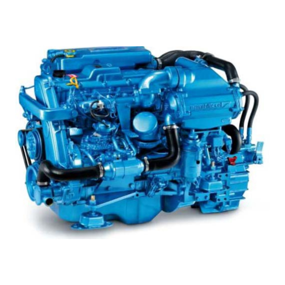
T4.155 4.380 TDI 4.390 TDI
W
O
R
K
S
H
O
P
M
A
N
U
A
L
W
O
R
K
S
H
O
P
M
A
N
U
A
L
4
C
y
l
i
n
d
e
r
s
4
C
y
l
i
n
d
e
r
s
ENGINE BASE
NANNI INDUSTRIES 11 Av MARIOTTE 33260 LA TESTE FRANCE Tel: +33 5 56 22 30 60 Fax: +33 5 56 22 30 79
E-mail: contact@nannidiesel.com
Web: www.nannidiesel.com
S.A.S au capital social de 2 040 000 € R.C.S Bordeaux B 380 707 638 000 17 APE 291 A TVA: FR 15380707638
60300140(
)
4 CYLINDERS WORKSHOP MANUAL
1/191
indice A
Advertisement
Table of Contents

Related Manuals for Nanni T4.155


Summary of Contents for Nanni T4.155
-
Page 1: Engine Base
T4.155 4.380 TDI 4.390 TDI ENGINE BASE NANNI INDUSTRIES 11 Av MARIOTTE 33260 LA TESTE FRANCE Tel: +33 5 56 22 30 60 Fax: +33 5 56 22 30 79 E-mail: contact@nannidiesel.com Web: www.nannidiesel.com S.A.S au capital social de 2 040 000 € R.C.S Bordeaux B 380 707 638 000 17 APE 291 A TVA: FR 15380707638... - Page 2 SOMMAIRE DU MANUEL D'ATELIER NANNI DIESEL Base M1KZ T 4.155 / 4.380 TDI / 4.390 TDI ALL TIGHTENING TORQUES ARE INDICATED IN Nm and in kgf/cm 1st part: Maintenance Manual Main components 28 Setting injection timing Safety information 31 Replacing the timing belt...
- Page 3 Manuel de Maintenance MOTEUR Base M1KZ T4.155 4.380 TDI 4.390 TDI T4.155 4.380 TDI 4.390 TDI (PART ONE) 60300140( 4 CYLINDERS WORKSHOP MANUAL 3/191 indice A...
- Page 4 60300140( 4 CYLINDERS WORKSHOP MANUAL 4/191 indice A...
- Page 5 60300140( 4 CYLINDERS WORKSHOP MANUAL 5/191 indice A...
-
Page 6: Safety Information
SAFETY INFORMATION This operating manual has been published to help you use your engine and its equipment. Numerous important instructions are given in this manual and need to be observed when operating the engine. The operator must read this manual. This manual must always be kept where the engine is used. - Page 7 Hot oil can burn. Allow the engine to cool before checking the oil level, replacing the oil or the oil filter cartridge. Always use the oils and fuels recommended by NANNI DIESEL. EXHAUST GAS PREVENTION Run the engine in a properly ventilated space away from people or animals. The accumulation of exhaust gas may be noxious.
-
Page 8: General Information
This operating manual contains all information required to ensure correct operation of the engine. NANNI INDUSTRIES is represented in more than 50 countries by its network of agents and vendors, and guarantees your safe navigation throughout the world. All services have been planned to meet your needs: spare parts, labor or just simply advice. - Page 9 IDENTIFICATION OF MAIN COMPONENTS Temperature exchanger Coolant filling port Block drain plug Fresh water pump Sea water pump Alternator Flexible suspension Electrical connector Starter Oil filling port Suction pipe for oil drainage pump Air filter Water injection exhaust elbow Anode Oil filter Oil pressure transmitter Gear reducer reverser...
- Page 10 DANGER: Do not bring a flame or sparks close to the battery. An extremely explosive detonating gas forms during battery charging. Do not cause a short circuit. The battery electrolyte is highly corrosive. If the acid is spilt on skin, immediately wash it with soapy water. If splashed into eyes, rinse generously with water and immediately consult a physician.
- Page 11 DANGER: Do not smoke or bring a flame or sparks close to fuel. Always wipe up spilled fuel. COOLING SYSTEM The system comprises two different circuits: the closed coolant circuit and the seawater circuit. Closed coolant circuit This circuit comprises a pump controlled by the crankshaft by means of two V belts, a water temperature exchanger, an oil temperature exchanger integrated in the block and a thermostat.
-
Page 12: Engine Operation
4. ENGINE OPERATION STARTING DANGERS - Correctly close the engine cover and fit all protection guards before starting the engine. Check the fuel level. Open the fuel supply valve. Open the seawater intake valve. Check the engine and reverser oil levels. Check the coolant level. - Page 13 All preventive maintenance operations, as well as related frequencies, are described in the guarantee logbook: SILVERWAKE®. These inspection operations govern the validity of the guarantee. They must be carried out by an approved NANNI DIESEL representative. New engines are guaranteed against any defective parts according to the methods specified in the SILVERWAKE®...
- Page 14 Cable terminals, as well as cables, must be correctly secured. Change the circuit load when the engine is running. Install a load distributor (Consult a NANNI DIESEL representative) to use several batteries. When starting with a spare battery and jumper leads, proceed as follows: Disregard the main battery circuit, connect the spare battery to the main battery by connecting the + to the + and the –...
- Page 15 WARNING: Never spray fuel onto the skin. Wear gloves. IMPORTANT: These works must be carried out by a NANNI DIESEL approved workshop. Injectors must be checked every 400 hours or every 2 years, according to the maintenance table and the SILVERWAKE® logbook.
- Page 16 Oil filter replacement The cartridge is of the disposable type. Connect a pipe to the sleeve of the filter head bowl and connect to a recipient. Unscrew the filter head cartridge. Coat the gasket of the cartridge with clean oil. Screw the new cartridge onto the filter head, then tighten by hand, ¾...
-
Page 17: Fiche Technique
- scraper: 0.20 – 0.50 mm limit: 0.87 mm EXHAUST TEMPERATURE CYLINDER HEAD T4.155: 450 ~ 500°C , 4.380 TDI: 570 ~ 600°C, 4.390 Flatness: < 0.15 mm TDI: 550~ 580°C SEA WATER PUMP Flow rate: 125 liters/min @ 3600 rpm... - Page 18 RECOMMENDATIONS LUBRICATION AND COOLING API -CD~CF 15 W 40 Mineral (MOTUL TEKMA MEGA OR MOTUL MARINE 50% PURE ANTIFREEZE 50% FRESH WATER (MOTUL ANTIFREEZE) 60300140( 4 CYLINDERS WORKSHOP MANUAL 18/191 indice A...
-
Page 19: Glow Plugs
ALTERNATOR BELTS GLOW PLUGS CHECKING THE ALTERNATOR DRIVE BELT CHECK THE ALTERNATOR DRIVE BELT a) Check the drive belt and verify the amount of fraying, clogging or wear. Check that the top of the drive belt does not touch the bottom of the pulley groove. - Page 20 WARNING: • "New belt" means a belt that is installed in an engine and that has rotated for less than 5 minutes. • "Worn belt" means a belt that is rotated in an engine and that has turned for at least 5 minutes. •...
- Page 21 CHECKING AND ADJUSTING VALVE CLEARANCE (ENGINE COLD) 1. REMOVE THE ROCKER COVER Remove the ten assembly bolts, the two attachment nuts, the rocker cover and the gasket. CYLINDER No.4 IS ON FLY WHEEL SIDE 2. PUT CYLINDER No.4 IN TOP DEAD POSITION a.
- Page 22 c) Only measure the clearance of the valves illustrated opposite. Measure the valve clearance . d) Remove the thickness shim. - Turn the crankshaft so as to position the peak of the cam shaft cam of the valve to adjust at the peak. - Use special maintenance tool SST to compress the valve lifter.
- Page 23 Selection table for thickness shims INTAKE Thickness of new thickness shim Intake valve clearance (measured cold): 0.20 – 0.30 Thickness Thickness Thickness Thickness shim No. shim No. EXAMPLE: 2.50 2.95 A 2,800 mm thickness shim is currently installed 2.55 3.00 and the measured clearance is 0,350 mm.
- Page 24 Selection table for thickness shims EXHAUST Thickness of new shims Intake valve clearance: 0.25 – 0.35 MM Thickness Thickness EXAMPLE: Thickness Thickness shim No. shim No. A 2,800 mm thickness shim is currently installed and 2.50 2.95 the measured clearance is 0,390 mm. Replace 2.55 3.00 thickness shim 2,900 by thickness shim no.11.
- Page 25 f) Install a new thickness shim. - Install the new thickness shim on the valve lifter. - Remove the special maintenance tool SST. g) Verify the valve operating clearance 4. INSTALLATION OF THE ROCKER COVER a) Remove any signs of former gasket on the joint (FIPG) b) Coat the locations illustrated in the figure opposite with sealant.
- Page 26 SETTING THE INJECTION ADVANCE CHECKING AND SETTING THE INJECTION TIMING Install the special maintenance tool SST and the dial gauge. a) Remove the bolt from the injection pump timing cap plug. b) Install the special maintenance tool SST (plunger stroke measurement tool reference: 970312378) and the dial gauge on the hole for the timing cap plug.
- Page 27 If the recorded value is not within the tolerances e) Loose the following assembly bolts and nuts. 1) The 4 attachment nuts of the injection pipe coupling on injection pump side. 2) The bolts securing the injection pump to the injection pump spacer. 3) The 2 attachment nuts securing the injection pump to the timing gear casing.
- Page 28 2) The bolts securing the injection pump on the injection pump space. Recommended tightening torque: 32 N.m (330 kgf.cm) * Verify the travel of the plunger piston 3) The four attachment nuts of the injection pipe coupling on injection pump side. Recommended tightening torque: 15 N.m (150 kgf.cm) REMOVE THE STEEL PLATE REMOVE THE SPECIAL MAINTENANCE TOOL SST AND DIAL...
- Page 29 REPLACING THE TIMING BELT EVERY 1000 HOURS or 2 YEARS REMOVING THE TIMING BELT (refer to the component part illustration for removal and reinstallation) 1) REMOVE THE TIMING BELT PROTECTION COVER Remove the four assembly bolts, the sealing washers, the two fasteners, the timing belt protection cover and the gasket.
- Page 30 CHECK OF THE TIMING BELT EQUIPMENTS CHECK THE INTERMEDIATE PULLEY Verify whether the timing belt intermediate pulley turns without any excessive friction. If necessary, replace the intermediate pulleys. PRECAUTION: REPLACE THE INTERMEDIATE PULLEY EACH TIME THE BELT IS REPLACED. CHECK THE TIMING BELT TENSIONER a) Examine the timing belt tensioner and verify whether oil leaks occur.
- Page 31 TEARING OFF OF 1 TOOTH (Engine blocking...) CRACKING (Intermediate pulley deformation...) SIDE TORN OFF (Pulley alignment...) SURFACE TORN OFF (Waste, impurities...) SEVERAL EXAMPLES OF BELT DAMAGE REQUIRING IMMEDIATE REPLACEMENT (Do not wait until it breaks) 60300140( 4 CYLINDERS WORKSHOP MANUAL 31/191 indice A...
- Page 32 REINSTALLATION OF TIMING BELT REINSTALL THE TIMING BELT REMARK: The engine must be cold ADVICE: If the timing belt is re-used, make the marks made during removal coincide, then reinstall the timing belt, taking care to point the arrow in the engine rotation direction 2) REINSTALL THE TIMING BELT INTERMEDIATE PULLEY a) Use a 10 mm hex head wrench, install the flat washer and the timing belt...
- Page 33 5) CHECK Turn the crankshaft clockwise and verify that each pulley coincides with the alignment marks (top dead center mark) as illustrated opposite. If the marks do not coincide, remove the timing belt and reinstall once more. 6) REINSTALL THE TIMING BELT PROTECTION COVER a) Remove signs of former sealant (FIPG).
- Page 34 COMPRESSION MEASUREMENT CHECKING THE COMPRESSION ADVICE: Measure cylinder compression pressure when the engine efficiency is low, oil consumption excessive or fuel consumption uneconomical. WARM THE ENGINE, THEN STOP IT Allow the engine to heat up to its normal operating temperature. 2) DISCONNECT THE INJECTION PUMP WIRING COUPLING UNIT (POWER SUPPLY CUTOFF CONTROL SOLENOID 3) REMOVE THE INJECTORS...
- Page 35 Compression pressure: 3.040 kPa (31.0 kgf/cm²) or more Minimum pressure: 1.961 kPa (20.0 kgf/cm²) Pressure difference between cylinders: Less than or equal to 490 kPa (5.0 kgf/cm²) e) If the compression pressure of one or more cylinders is less than that of the other cylinders, pour a small amount of engine oil in the injection port and repeat checking operations a.
- Page 36 PISTON PROTRUSION SELECTION OF THE CYLINDER HEAD GASKET REINSTALLATION AND TIGHTENING OF THE CYLINDER HEAD 1) CHECK THE PROTRUDING PART OF THE PISTON AND CHOOSE AN APPROPRIATE CYLINDER HEAD JOINT A) Check the protruding part of the piston of each cylinder. a) Carefully clean the cylinder block assembly surface with a grease remover.
- Page 37 B) Select a new cylinder head gasket. WARNING: There are 5 types of cylinder head gaskets (hole No.1 to 5) which are installed in the factory but only 3 types as procurement parts (hole No. "1", "3", and "5") so that when replacing a cylinder head gasket, the choice of the gasket must be from amongst these 3 types proposed.
- Page 38 B) Reinstall cylinder head bolts. WARNING: - Cylinder bolts must be tightened gradually in three step (step (b), (d) and (e)). - Any broken or deformed cylinder head bolt must be replaced. a) Put a drop of engine oil on bolt threads and under bolt heads before reinstalling them.
- Page 39 b) Reinstall the five bearing caps at their respective locations. c) Reinstall and evenly tighten the ten bearing cap bolts to the recommended torque, in the tightening order indicated opposite. Recommended tightening torque: 18 N.m (185 kgf.cm) 5. REINSTALL THE CAM SHAFT OIL GASKET RETAINER a) Carefully remove all signs of former sealant (FIPG) from mating surfaces and take care not to dirty the assembly surfaces of the cylinder head and cam shaft oil gasket retainer with oil.
- Page 40 CHECKING THE COOLING SYSTEM COMPONENTS FREQUENCY: REFER TO MAINTENANCE PLAN HARDWARE IN DIRECT CONTACT WITH SEA WATER MUST BE MADE OF A4.70 STAINLESS STEEL SEA WATER PUMP: Replacing the rotor and cover gasket THERMOSTAT: Opening temperature check, replacement OPENING: 71°C COOLERS: for gearbox, stern drive oil and Fuel (only 4.390TDI)
- Page 41 EXCHANGER: Clean the core and replace o-rings CAUTION: Core securing screw in exchanger body. INTERCOOLER: Clean the core and replace o-rings 60300140( 4 CYLINDERS WORKSHOP MANUAL 41/191 indice A...
- Page 42 ANODE ON EXHAUST ELBOW: Check and replace COOLANT: PURE ANTIFREEZE, FRESH WATER IMPORTANT: BLEED THE FRESH WATER CIRCUIT ON THE TURBO CHARGER 60300140( 4 CYLINDERS WORKSHOP MANUAL 42/191 indice A...
- Page 43 INDICATORS: Pre-heating Water in fuel and water alarm Oil alarm Battery charging PANEL C3: rectangular connector INDICATORS: Water in fuel Water alarm Oil alarm Battery charging PANEL C3: round connector 60300140( 4 CYLINDERS WORKSHOP MANUAL 43/191 indice A...
- Page 44 60300140( 4 CYLINDERS WORKSHOP MANUAL 44/191 indice A...
- Page 45 TOYOTA 4 cylinder BASE PANEL CONNECTORS MALE CONNECTORS LUG SIDE VIEW 4 CYLINDERS TOYOTA SQUARE CONNECTOR 11 terminals + 2 terminals TERMINAL No. WIRE COLOUR FUNCTION BATTERY + BLACK BATTERY - BROWN STARTER BROWN 1 PRE-HEATING WHITE STOP GREY OIL PRESSURE SWITCH PURPLE ALTERNATOR LOAD GREY 1...
- Page 46 60300140( 4 CYLINDERS WORKSHOP MANUAL 46/191 indice A...
- Page 47 ENGINE HARDNESS CONNECTOR ROUND MODEL BATTERY + PURPLE CHARGE INDICATOR GREY OIL PRESSURE PROBE YELLOW PRE-HEATING PINK / BLACK OIL ALARM YELLOW / GREEN WATER ALARM BROWN STARTING ORANGE / BLUE WATER TEMPERATURE PROBE GREEN PRE-HEATING TIMEOUT PROBE WHITE ENGINE STOP BLUE + REV COUNTER BLUE / GREY...
- Page 48 ELECTRICAL DRAWING Rectangular connector 60300140( 4 CYLINDERS WORKSHOP MANUAL 48/191 indice A...
- Page 49 60300140( 4 CYLINDERS WORKSHOP MANUAL 49/191 indice A...
- Page 50 970 312 377 • Injection pump dial gauge support 970 312 378 • Pulley / pinion extractor box (usable on all NANNI models) 970 312 374 • Valve spring compressor 970 312 372 • Combustion chamber extractor 970 312 373 •...
- Page 51 CONTENTS EXPLODED VIEW OF THE 4 CYLINDERS TOYOTA base ENGINE TIMING BELT TIMING CASING TIMING PINIONS CYLINDER HEAD CYLINDER BLOCK GLOW PLUGS INJECTORS INJECTION PUMP THERMOSTAT FRESH WATER PUMP OIL PUMP OIL RADIATOR OIL INJECTORS TURBO CHARGER 60300140( 4 CYLINDERS WORKSHOP MANUAL 51/191 indice A...
-
Page 52: Timing Belt
Cylinder Head cover TIMING BELT COMPONENT PARTS REMOVAL AND REINSTALLATION Gasket Cam shaft No.1 tightening pulley Fastener Timing belt Intermediate timing pulley Timing belt tensioner Cam shaft No.2 distribution pulley Gasket Cam shaft No.2 timing pulley flange Specified tightening torque - Non-reusable part 60300140( 4 CYLINDERS WORKSHOP MANUAL... - Page 53 60300140( 4 CYLINDERS WORKSHOP MANUAL 53/191 indice A...
- Page 54 60300140( 4 CYLINDERS WORKSHOP MANUAL 54/191 indice A...
- Page 55 60300140( 4 CYLINDERS WORKSHOP MANUAL 55/191 indice A...
- Page 56 60300140( 4 CYLINDERS WORKSHOP MANUAL 56/191 indice A...
- Page 57 60300140( 4 CYLINDERS WORKSHOP MANUAL 57/191 indice A...
- Page 58 60300140( 4 CYLINDERS WORKSHOP MANUAL 58/191 indice A...
- Page 59 60300140( 4 CYLINDERS WORKSHOP MANUAL 59/191 indice A...
- Page 60 60300140( 4 CYLINDERS WORKSHOP MANUAL 60/191 indice A...
- Page 61 60300140( 4 CYLINDERS WORKSHOP MANUAL 61/191 indice A...
- Page 62 60300140( 4 CYLINDERS WORKSHOP MANUAL 62/191 indice A...
- Page 63 60300140( 4 CYLINDERS WORKSHOP MANUAL 63/191 indice A...
- Page 64 60300140( 4 CYLINDERS WORKSHOP MANUAL 64/191 indice A...
- Page 65 60300140( 4 CYLINDERS WORKSHOP MANUAL 65/191 indice A...
- Page 66 Manuel de Maintenance MOTEUR Base M1KZ T4.155 4.380 TDI 4.390 TDI T4.155 4.380 TDI 4.390 TDI (PART TWO) 60300140( 4 CYLINDERS WORKSHOP MANUAL 66/191 indice A...
- Page 67 Tightening torques (standard) Specific tightening torques Characteristics Special tooling Timing pinions Cylinder head Injection pump and injector Fresh water pump and sender, thermostat Pre-heating Oil pressure, oil injectors, oil pump, oil radiator Turbo charger Cylinder block Your notes Setting, adjustment and maintenance operations are described in MAINTENANCE MANUAL 60300140( 4 CYLINDERS WORKSHOP MANUAL...
- Page 68 60300140( 4 CYLINDERS WORKSHOP MANUAL 68/191 indice A...
- Page 69 SPECIFIC STANDARD BOLT TORQUE Tightening torque Hex head bolt Diameter Pitch Hex head bolt Category with collar kgf.cm kgf.cm 1.25 12.5 1.25 1.25 1150 1.25 15.5 17.5 1.25 1.25 1050 1400 1.25 1.25 1.25 1100 1250 1750 10.5 1.25 1.25 1.25 1050 1500...
- Page 70 SPECIFIC TIGHTENING TORQUES TIGHTENING TORQUES Component to tighten kgf.cm Intake pipe x intake manifold Injection pump x timing gear casing Injection pump x injection pump spacer Injection pump tightening head cap bolt Cam shaft No.1 tightening pulley x cam shaft 1000 Cam shaft No.2 tightening pulley x injection pump drive pinion...
- Page 71 ENGINE CHARACTERISTICS MAINTENANCE CHARACTERISTICS MAINTENANCE DATA Engine tuning API quality engine oil CD or greater Alternator drive belt sag under a 98 N (10kgf) force New belt Worn belt 6 – 8mm 8 – 12mm Alternator drive belt tension with special maintenance tool SST New belt 45 –...
- Page 72 Cylinder head Deformation Limit 0.15 mm Valve seat Grinding angle 30°, 45° , 60° Contact angle 45° Contact width Intake 1.5 – 1.9 mm Exhaust 1.8 – 2.2 mm Outside diameter of the cylinder head assembly bolts 11.8 – 12.0 mm 11.6 mm Limited Installed cylinder head gasket thickness...
- Page 73 Combustion Protrusion less 0.03 – more 0.02 mm chamber Thickness shim thickness 0.05 mm 0.10 mm Cylinder block Cylinder head surface warp Limit 0.10 mm Cylinder bore diameter STD (Item 1) 96.000 – 96.010 mm (Mark 2) 96.010 – 96.020 mm (Mark 3) 96.020 –...
- Page 74 Connecting rod Piston pin lubrication clearance 0.008 – 0.016 mm Limit 0.03 mm Connecting rod small end inner diameter (Reference) STD (Item 1) 62.014 – 62.020 mm (Item 2) 62.020 – 62.026 mm (Item 3) 62.026 – 62.032 mm Crankshaft Stop clearance Piston pin lubrication clearance 0.04 –...
- Page 75 • Valve adjustment tool: 970 312 377 • Injection pump dial gauge support 970 312 378 • Pulley/pinion extractor box (Usable on all NANNI models) 970 312 374 • Valve spring compressor 970 312 372 • Combustion chamber extractor 970 312 373 •...
- Page 76 60300140( 4 CYLINDERS WORKSHOP MANUAL 76/191 indice A...
- Page 77 60300140( 4 CYLINDERS WORKSHOP MANUAL 77/191 indice A...
- Page 78 1. REMOVE THE TIMING BELT PROTECTION COVER Remove the four assembly bolts, the sealing washers, the two fasteners, the timing belt protection cover and the gasket. 2. PUT No.4 CYLINDER IN TOP DEAD CENTER POSITION ON ITS COMPRESSION STROKE Rotate the crankshaft fully clockwise to make the notches in No.1 and No.2 cam shaft pulleys coincide with the top dead center timing marks 3.
- Page 79 6. REMOVE THE TIMING BELT 7. REMOVE CAM SHAFT No.2 TIMING PULLEY Remove the four assembly bolts, the cam shaft No.2 timing pulley flange and the cam shaft No.2 timing pulley. 8. REMOVE THE ROCKER COVER Remove the ten assembly bolts, the two attachment nuts, the rocker cover and the gasket.
- Page 80 REMOVING THE TIMING PINIONS (Refer to component part illustration for disassembly and reassembly) 1. REMOVE THE TIMING BELT 2. REMOVE THE TIMING BELT AND PULLEYS 3. REMOVE THE CAM SHAFT OIL GASKET RETAINER Remove the seven assembly bolts and cam shaft oil gasket retainer.
- Page 81 c. Remove the thirteen assembly bolts and the two attachment nuts. c. Prise opens the timing cover. d. Remove the o-ring 6. CHECK THE AXIAL CLEARANCE OF THE INTERMEDIATE TOOTHED WHEEL Use a dial gauge to measure the axial clearance of the intermediate toothed wheel.
- Page 82 7. REMOVE THE TIMING TOOTHED WHEELS REMARK: * The alignment mark engraved on the surface of each toothed wheel is directed towards the front of the engine * Make sure not to damage the teeth of the toothed wheels when removing and reinstalling toothed wheels.
- Page 83 c. Remove the injection pump drive pinion using the special maintenance tool. REMARK: * Tighten the two assembly bolts of the special maintenance tool SST on more than 8mm * Install the special maintenance tool SST so that it is balanced 8.
- Page 84 f. Install the intermediate toothed wheel in a vice. REMARK: Make sure not to damage the toothed wheels during this operation. g. Remove the snap ring with snap ring pliers. h. Remove the following parts: (1) Star washer (2) No.2 secondary intermediate toothed wheel (3) Intermediate toothed wheel spring 60300140( 4 CYLINDERS WORKSHOP MANUAL...
-
Page 85: Gear Bearing
CHECKING THE TOOTHED WHEEL TIMING 1. VERIFY INTERMEDIATE TOOTHED WHEELS a. Measure the inside diameter of each intermediate toothed wheel using a bore gauge. Intermediate toothed wheel inside diameter: 44.000 – 44.025 mm b. Measure the outside diameter of the intermediate toothed wheel shaft using a micrometer. - Page 86 B. Reinstall the bearing Use the special maintenance tool SST and a press to fit the bearing. 4. CHECK THE REACTIVE CLEARANCE OF THE TIMING TOOTHED WHEEL TEETH Install the dial gauge to measure the teething reactive clearance between each toothed wheel of the timing. Nominal teething reactive clearance: 0.02 –...
- Page 87 REPLACING THE CRANKSHAFT OIL GASKET ADVICE: There are two methods of replacing the oil gasket (A and B) as described below REPLACE THE CRANKSHAFT OIL GASKET A. When the timing casing cover is separate from the cylinder block: a. Use a screw driver and a hammer to drive out the oil gasket. b.
- Page 88 REPLACING THE INJECTION PUMP OIL SEAL WARNING: There are two methods of replacing the oil gasket (A and B) as described below REPLACE THE INJECTION PUMP PINION OIL GASKET A. When the timing casing cover is separate from the cylinder block: a.
- Page 89 REINSTALLING THE TIMING PINIONS (Refer to component part illustration for disassembly and reassembly) 1. REMOVE THE INTERMEDIATE TOOTHED WHEEL a. Install the intermediate toothed wheel in a vice. WARNING: Install the intermediate toothed wheel making sure to direct the marking notch downwards.
- Page 90 g. Remove the service bolt. h. Reinstall the following parts: (1) Intermediate toothed wheel spring (2) No.1 secondary intermediate toothed wheel (3) Star washer ADVICE: Make the pawls of the toothed wheels coincide with the spring ends. Reinstall the snap ring with snap ring pliers. j.
- Page 91 A. Reinstall the crankshaft timing toothed wheel a. Verify that the crankshaft assembly key is correctly positioned upwards to reinstall the crankshaft timing toothed wheel on the crankshaft. b. When this is done, the alignment marks of the oil pump shaft drive toothed wheel and the tooth wheel must correspond to position "1".
- Page 92 b. Reinstall the cylinder block intermediate toothed wheel shaft. c. Make the timing adjustment marks "5" and "4" of the intermediated toothed wheel assembly, coincide respectively with the timing setting mark "5" of the crankshaft and the timing setting mark "4" of the injection pump drive pinion then engage timing toothed wheels mesh.
- Page 93 3. REINSTALL THE TIMING CASING COVER a. Reinstall a new o-ring on the timing casing cover b. Carefully remove any signs of former sealant (FIPG) from application surfaces and take care not to dirty the assembly surfaces between the timing casing cover and the cylinder block.
- Page 94 4. CHECK THE AXIAL CLEARANCE OF THE INJECTION PUMP DRIVE GEAR a. Temporarily remove the flange and the No.2 cam shaft timing pulley with the four assembly bolts. b. Move cam shaft No.2 timing pulley from the front to the back and check the axial clearance of the injection pump pinion shaft.
- Page 95 6. REINSTALL THE SEA WATER PUMP Recommended tightening torque: 21 N.m (210 kgf.cm) 7. REINSTALL THE CAM SHAFT OIL GASKET RETAINER Reinstall the cam shaft oil gasket retainer with the seven assembly bolts. Recommended tightening torque: 9 N.m (90 kgf.cm) 8.
- Page 96 60300140( 4 CYLINDERS WORKSHOP MANUAL 96/191 indice A...
- Page 97 REMOVE THE INTAKE MANIFOLD a. Disconnect the following wiring connection block * Water temperature sender gauge wiring connection block b. Disconnect the flexible pipe from the injection pump. c. Remove the rubber insulating washer, the attachment nut and the cable. d.
- Page 98 REMARK: * This engine is fitted with ceramic glow plugs. To prevent damaging the glow plugs, do not remove them unless it is absolutely necessary. * Before removing the glow plugs, refer to the page in this manual discussing how glow plugs must be handled. DRAIN THE ENGINE COOLANT.
- Page 99 REMOVE THE TIMING BELT AND THE PULLEYS REMOVE THE CAM SHAFT OIL SEAL RETAINER a. Remove the seven assembly bolts securing the camshaft oil seal retainer to the cylinder head. b. Remove the cam shaft oil seal retainer to separate it. REMOVE THE CAMSHAFT a.
-
Page 100: Removing The Cylinder Head
REMOVE THE CYLINDER HEAD a. Uniformly and gradually loosen the eighteen cylinder head bolts in several stages and in the order indicated on the illustration. REMARK: Cylinder head warping or cracking may occur if the bolts are not loosened and removed in the indicated order. - Page 101 ADVICE: Remove the valve lifters and thickness shims in the disassembly order. REMOVE VALVES a. Compress valve springs using special maintenance tool SST and remove the two half-keys. b. Remove the spring cup retainer, the valve spring, the valve and the valve cup. ADVICE: Remove valves, valve spring cups and spring cup keys in the disassembly order.
- Page 102 ADVICE: Lay out the combustion chambers in the logical disassembly order. REMOVE THE SEMI-CIRCULAR CAP CHECKING, MAINTENANCE AND RECONDITIONING OF COMPONENT PARTS OF THE CYLINDER HEAD 1. CLEAN THE TOP OF THE PISTON AND THE TOP SURFACE OF THE CYLINDER BLOCK a.
- Page 103 C. Clean valve guide bushes Use a valve guide bush brush and a solvent to carefully clean the valve guide bushes. D. Clean the cylinder head Use a flexible bristle brush and solvent to carefully clean the cylinder heads. 3. CHECKING THE CYLINDER HEAD A.
- Page 104 4. CLEAN THE VALVES a. Use a gasket scraper to separate any accumulation of carbon deposits on the tops of valves. b. Use a metal brush to carefully clean valves. 5. CHECK RODS AND VALVE GUIDES a. Measure the inside diameter of each valve guide using a micrometer.
- Page 105 6. IF NECESSARY, REPLACE VALVE GUIDE BUSHES a. Drive out the valve guide using the special maintenance tool SST and a hammer. b. Use an inside micrometer to measure the bore of the cylinder head valve guide bushes c. Select a new valve guide bush (nominal dimension or dimension greater by 0.05).
- Page 106 7. EXAMINE AND GRIND VALVES a. Only grind valves with an electric grinder if surface pitting or carbon deposits need to be removed. b. Make sure that the angle of the sealing surface of valves is ground to the indicated dimension. Valve sealing surface angle: 45.5°...
- Page 107 8. EXAMINE AND CLEAN THE VALVE SEATS a. re-bore the valve seats using a 45° carbide reamer and essentially remove the amount of material making it possible to return the seats to good condition. b. Check the bearing surface of the valve on its seat. Apply a fine coat of the engineer blue (or white lead) on the surface of the valve.
- Page 108 9. CHECKING VALVE SPRINGS a. Use a metal square to measure the squareness of the valve springs. Squaring limit: 2.0 mm Replace the valve spring if the maximum squaring is exceeded. b. Use a slide caliper to measure the length of the valve spring, not pressed.
- Page 109 Minimum cam peak height: Intake : 54.39 mm Exhaust: 55.72 mm Replace the camshaft if the height of the cam peak is less than the minimum limit. C. Check cam shaft pivot Measure the diameter of the pivot using a micrometer. Nominal diameter: 27.969 –...
- Page 110 e. Remove the bearing caps. f. Measure the widest part of the plastigage. Nominal lubrication clearance: 0.025 – 0.062 mm Lubrication clearance limit: 0.10 mm Only replace the cam shaft if the maximum limit is exceeded. Replace bearing caps and the cylinder head as a matched pair if necessary. g.
- Page 111 c. Subtract the valve lifter diameter measurement from the valve bore diameter. Nominal lubrication clearance: 0.038 – 0.063 mm Lubrication clearance limit: 0.08 mm Replace the valve lifter if the lubrication clearance limit is exceeded. If necessary, replace the cylinder head. 12.
- Page 112 REPLACING THE CAM SHAFT OIL GASKET ADVICE: There are two methods of replacing the oil gasket (A and B) as described below REPLACE THE CAM SHAFT OIL GASKET A. When the cam shaft oil gasket retainer is taken off the cylinder head: a.
- Page 113 REINSTALL THE CYLINDER HEAD (Refer to the component part illustration for disassembly and reassembly) ADVICE: * Carefully clean all parts to assemble. * Before starting to assemble the parts, coat all rotating and sliding surfaces with fresh engine oil. * Reinstall new oil seals and rings 1.
- Page 114 2. REINSTALL THE COMBUSTION CHAMBERS a. Make the combustion chamber position pin coincide with the corresponding recess in the cylinder head. b. Use a plastic mallet to fit the combustion chambers and position them. c. Use a dial gauge to verify the amount the combustion chambers protrude.
- Page 115 c. Lightly strike the end of the valve stem with the plastic mallet to verify that it is correctly positioned. 4. REINSTALL THE VALVE LIFTERS WITH THEIR THICKNESS SHIMS a. Reinstall the valve lifters and thickness shims. b. Check that the valve lifters turn normally when moved by hand.
- Page 116 REINSTALLING THE CYLINDER HEAD 1. VERIFY THE PROTRUDING PART OF THE PISTON AND CHOOSE THE CORRESPONDING CYLINDER HEAD GASKET A. Verify the protruding part of the piston of each cylinder. a. Carefully clean the cylinder block assembly surface with a grease remover.
- Page 117 B. Select a new cylinder head gasket. ADVICE: There are 5 types of cylinder head gaskets (hole No.1 to 5) which are installed in the factory but only 3 types as procurement parts (hole No. "1", "3", and "5") so that when replacing a cylinder head gasket, the choice of the new gasket must be from amongst these 3 types proposed.
- Page 118 B. Reinstall cylinder head bolts. ADVICE: * Cylinder bolts must be tightened gradually in three stages (stages (b), (d) and (e)). * Any broken or deformed cylinder head bolt must be replaced. a. Put a drop of engine oil on bolt threads and under bolt heads before reinstalling them.
- Page 119 b. reinstall the five bearing caps at their respective locations. c. Reinstall and evenly tighten the ten bearing cap bolts to the recommended torque, in the tightening order indicated opposite. Recommended tightening torque: 18 N.m (185 kgf.cm) 5. REINSTALL THE CAMSHAFT OIL GASKET RETAINER a.
- Page 120 * Parts must be assembled within 5 minutes of the product being applied. Otherwise the sealant must be entirely removed and reapplied. * Immediately remove the nozzle from the tube and tighten the closing cap. c. Coat two or three threads at the end of assembly bolts with sealant d.
- Page 121 60300140( 4 CYLINDERS WORKSHOP MANUAL 121/191 indice A...
- Page 122 60300140( 4 CYLINDERS WORKSHOP MANUAL 122/191 indice A...
- Page 123 REMOVE THE INJECTION PIPES a. Loosen the two nuts securing fasteners (A) on the intake manifold. b. Use a screwdriver to prise off the fastener (B). c. Loosen the eight injection pipe attachment coupling nuts. d. Remove the four injection pipes and the two pipe retainers (A).
- Page 124 ADVICE: Remove the injectors in the logical order corresponding to the cylinders INJECTOR TEST INJECTION PRESSURE TEST a. Install the injector to check on an injector test bench and bleed out the air by the coupling nut PRECAUTION: Never put a finger in front of the injector injection hole.
- Page 125 Thickness shim thickness ADVICE: * Modifying the thickness of the thickness shim by 0.025 mm makes the injection pressure change by approx. 471 kPa (4.8 kgf/cm²). * Only one thickness shim should be used. e. Verify that no fuel drops are found during post-detection DROP TEST Hold the pressure at approx.
- Page 126 COMPONENT PART DISASSEMBLY AND REASSEMBLY DISASSEMBLING THE INJECTORS DISASSEMBLE THE INJECTORS a. Use special maintenance tool SST to loosen the injector carrier attachment nut. REMARK: When disassembling the injector, make sure not to let any internal parts fall. b. Remove the pressure spring, the thickness shim, the pressure pin, the spacing part and the injector.
- Page 127 b. remove the carbon deposits accumulated at the end of the injector needle valve with the bar c. Use a brass bristle brush to remove the carbon deposits from the external parts of the injector nozzle (without touching the lapped surface). d.
- Page 128 REASSEMBLING THE INJECTORS Refer to the component part illustration for disassembly and reassembly operations) REINSTALL THE INJECTOR a. Reinstall the injector carrier attachment nut, the complete injector, the spacing part, the pressure pin, the pressure spring, the thickness adjustment shim and the injector carrier body.
- Page 129 REINSTALL THE INJECTOR PIPES a. Temporarily reinstall the four injection pipes and the two fasteners (A) b. Reinstall the two attachment nuts securing the fasteners (A) to the intake manifold. Recommended tightening torque: 6 N.m (65 kgf.cm) c. Use a screwdriver to secure the fastener (B). Tighten the eight coupling nuts to the recommended tightening torque.
- Page 130 60300140( 4 CYLINDERS WORKSHOP MANUAL 130/191 indice A...
- Page 131 a) Immobilize the crankshaft pulley and remove the injection pump drive pinion attachment nut b) Remove the three assembly bolts and the injection pump spacer. c) Before removing the injection pump, check whether the timing lines are aligned. If this is not the case, make new alignment marks on the injection pump to facilitate reassembly.
- Page 132 CHECKING THE WATER TEMPERATURE SENSOR 1. REMOVE THE WATER TEMPERATURE SENSOR 2. VERIFY THE WATER TEMPERATURE SENSOR Use the special maintenance tool SST to verify the resistance between the terminals using an ohmmeter. Resistance: (Refer to the diagram) If the resistance is not within the limits stipulated in specifications, replace the water temperature sensor 3.
- Page 133 60300140( 4 CYLINDERS WORKSHOP MANUAL 133/191 indice A...
- Page 134 REMOVING THE WATER PUMP (Refer to component part illustration for disassembly and reassembly) 1. DRAIN THE ENGINE COOLANT 2. REMOVE THE DRIVE BELT AND THE WATER PUMP PULLEY a. Pull the drive belt as much as possible and loosen the four water pump pulley attachment nuts.
- Page 135 d. Remove the assembly bolt, the water pump cover and the gasket. REASSEMBLING THE WATER PUMP (Refer to component part illustration for removal and reinstallation) 1. REINSTALL THE COMPLETE WATER PUMP a. Install a new gasket on the water pump cover. b.
- Page 136 f. Reinstall the alternator with the pivot bolt and the lock bolt. Recommended tightening torque: 21 N.m (210 kgf.cm) for the lock bolt Recommended tightening torque: 62 N.m (620 kgf.cm) for the pivot bolt 2. REINSTALL THE CAM SHAFT OIL SEAL RETAINER 3.
- Page 137 REMOVING THE THERMOSTAT (Refer to component part illustration for removal and reinstallation) ADVICE: Simply removing the thermostat may have a negative effect and cause a decrease to cooling system efficiency. Do not remove the thermostat, even if the engine has a tendency to overheat 1.
-
Page 138: Checking The Thermostat
CHECKING THE THERMOSTAT CHECK THE THERMOSTAT ADVICE: The thermostat is marked with a number according to the valve opening temperature. a. Dip the thermostat into water and heat the water gradually. b. Verify the valve opening temperature. Valve opening temperature: 71°C Replace the thermostat when the valve opening temperature is not within the limits complying with specifications. - Page 139 GLOW PLUGS COMPONENT PART (REMOVAL AND REINSTALLATION) REMARK: * Cylinder head seizing and opening of glow plugs may occur if carbon deposits accumulate. Also, twisting the glow plugs excessively when removing them may cause the ceramic to split. Consequently, wherever possible avoid moving glow plugs.
- Page 140 REMOVE THE GLOW PLUGS a. Remove the four screw insulating washers. b. Remove the four attachment nuts and the connection plate of the glow plugs c. Use a box spanner, depth 12 mm, to remove the four glow plugs. REINSTALLING THE GLOW PLUGS (refer to component part illustration for removal and reinstallation) REMARK:...
- Page 141 d. Use a 12 mm deep box spanner to reinstall the four glow plugs. Recommended tightening torque: 13 N.m (130 kgf.cm) CHECKING ON BOARD REMARK: When checking the glow plug resistance, the engine must on board. Avoid removing and reinstalling glow plugs as far as possible.
-
Page 142: Checking The Oil Pressure
OIL PRESSURE, OIL INJECTORS, OIL PUMP, OIL COOLER CHECKING THE OIL PRESSURE 1. CHECK THE ENGINE OIL QUALITY Check the level of quality of the oil, infiltration of water in the oil, its colour and its lubrication capacity. Drain the engine oil if the quality is bad. Oil quality: API CD oil quality or greater. - Page 143 REMOVE OIL JETS 1. DRAIN THE ENGINE OIL 2. REMOVE THE ENGINE BOTTOM CASING 3. REMOVE THE CHECK VALVE AND THE OIL JETS Remove the four check valves and the oil jets. CHECKING OIL JETS 1. CHECK THE CHECK VALVES Press the check valve with a piece of hard wood and verify whether it sticks.
- Page 144 2. CHECK OIL JETS Check the degree of damage or clogging of oil jets. If necessary, replace it. REINSTALLING OIL JETS (Refer to component part illustration for removal and reinstallation) 1. REINSTALL OIL JETS AND THE CHECK VALVES a. Make the lubrication injector pin coincide with the corresponding hole in the cylinder block.
- Page 145 60300140( 4 CYLINDERS WORKSHOP MANUAL 145/191 indice A...
-
Page 146: Removing The Oil Pump
REMOVING THE OIL PUMP (Refer to component part illustration for removal and reinstallation) ADVICE: When repairing the oil pump, carefully clean the engine bottom casing and remove the oil strainer to clean it. 1. DRAIN THE ENGINE COOLANT 2. DRAIN THE ENGINE OIL 3. - Page 147 10. REMOVE THE OIL STRAINER Remove the two attachment bolts, two nuts and the oil strainer and gasket 11. REMOVE THE OIL PUMP TIMING CASING Before removing the two nuts securing the injection pump flange on the timing casing, verify that the timing lines coincide correctly. Otherwise mark alignment marks to facilitate reassembly.
-
Page 148: Checking The Oil Pump
DISASSEMBLING THE OIL PUMP (Refer to component part illustration for removal and reinstallation) 1. REMOVE THE DRIVEN ROTOR. 2. REMOVE THE DISCHARGE VALVE. Remove the threaded cap, the gasket, the spring and the discharge valve. CHECKING THE OIL PUMP 1. CHECK THE DISCHARGE VALVE. Put engine oil on the discharge valve and verify that it falls normally under its own weight in the bore. - Page 149 C. Verify the rotor side clearance Use a set of thickness shims and a ground precision rule to measure the side clearance between the rotor and the ground precision rule. Nominal side clearance: 0.030 – 0.090 mm Limit side clearance: 0.15 mm Replace rotors if the clearance recorded is greater than the indicated limit.
- Page 150 REINSTALLING THE OIL PUMP Refer to component part illustration for removal and reinstallation) REINSTALLING THE OIL PUMP (TIMING CASING) a. Remove all signs of former sealant (FIPG) and take care not to dirty contact surfaces of the timing casing and cylinder block.
- Page 151 e. Reinstall the distribution casing. f. Make the mark made on the driven pinion of No.1 balancing shaft correspond with mark "2". g. Make the mark made on the oil pump drive pinion coincide with the mark made on the timing casing. h.
- Page 152 c. Coat two or three threads of the threaded section of the tapered threaded plug with sealant. Adhesive product: LOCTITE 242 or similar product. d. reinstall the tapered threaded plug REINSTALL THE OIL STRAINER Reinstall a new gasket at the oil strainer then secure with the two assembly bolts and the two attachment nuts.
- Page 153 REINSTALL THE WATER PUMP REINSTALL THE ALTERNATOR AND THE ALTERNATOR ATTACHMENT PLATE REINSTALL THE ALTERNATOR ADJUSTMENT Reinstall the adjustment bar with the assembly bolt and the lock bolt. Recommended tightening torque: 21 N.m (210kgf.cm) REINSTALL THE TIMING GEARS REINSTALL THE TIMING BELT REINSTALL THE WATER PUMP PULLEY AND THE DRIVE BELT FILL THE ENGINE WITH ENGINE OIL...
- Page 154 60300140( 4 CYLINDERS WORKSHOP MANUAL 154/191 indice A...
- Page 155 REMOVING THE OIL RADIATOR AND THE DISCHARGE VALVE 1. DRAIN THE COOLANT FROM THE ENGINE 2. REMOVE THE TIMING BELT 3. REMOVE THE INJECTION PIPELINES 4. REMOVE THE INJECTION PUMP 5. REMOVE THE OIL LEVEL GAUGE AND ITS GUIDE a. Remove the attachment nut and the oil level gauge guide assembly.
- Page 156 9. SEPARATE THE OIL RADIATOR FROM THE OIL RADIATOR CASING Remove the four nuts, the oil radiator, and the two seals from the oil radiator cover. 10. REMOVE THE DISCHARGE VALVE 11. REMOVE THE OIL DRAIN PLUG CHECKING THE OIL COOLER AND THE DISCHARGE VALVE 1.
- Page 157 REINSTALLING THE OIL RADIATOR AND THE DISCHARGE VALVE (Refer to component part illustration for removal and reinstallation) 1. REINSTALL THE ENGINE OIL PLUG Recommended tightening torque: 8 N.m (80 kgf.cm) 2. REINSTALL THE DISCHARGE VALVE Reinstall a new gasket on the discharge valve. Recommended tightening torque: 39 N.m (400 kgf.cm) 3.
- Page 158 5. REINSTALL THE OIL COOLER AND THE OIL COOLER CASING ASSEMBLY a. Reinstall a new gasket, the oil radiator casing assembled to the oil radiator with the thirteen bolts. Recommended tightening torque: 13 N.m (130 kgf.cm) 6. REINSTALL THE OIL LEVEL GUIDE AND THE OIL LEVEL GAUGE Reinstall a new o-ring on the oil level gauge guide.
- Page 159 60300140( 4 CYLINDERS WORKSHOP MANUAL 159/191 indice A...
- Page 160 CHECKING THE TURBO CHARGER 1. CHECK ROTATION OF THE IMPELLER Take the edge of the turbine impeller and rotate it. Verify that the impeller turns without offering any resistance. If the impeller does not turn, or if it turns and rubs, replace the turbo charger.
- Page 161 60300140( 4 CYLINDERS WORKSHOP MANUAL 161/191 indice A...
- Page 162 REMOVAL PREPARATION 1- REMOVE THE ENGINE FLY WHEEL 2- INSTALL THE COMPLETE ENGINE ON AN APPROPRIATE SUPPORT IN ORDER TO DISASSEMBLE IT 3- REMOVE THE TIMING BELT AND THE TIMING PULLEYS 4- REMOVE THE CYLINDER HEAD 5- REMOVE THE ALTERNATOR AND THE ALTERNATOR ATTACHMENT PLATE 6- REMOVE THE WATER PUMP 7- REMOVE THE TIMING GEARS...
- Page 163 DISASSEMBLING THE CYLINDER BLOCK (Refer to component part illustration for disassembly and reassembly) 1. REMOVE THE REAR OIL GASKET RETAINING CAGE Remove the five assembly bolts and the rear oil gasket retaining cage. 2. MEASURE THE AXIAL CLEARANCE OF THE LEFT AND RIGHT BALANCING SHAFTS OF THE MOTOR COMPENSATOR Measure the axial clearance of the balancing shafts using a dial gauge...
- Page 164 5. MEASURE THE CONNECTING ROD AXIAL CLEARANCE Measure the connecting rod axial clearance using a dial gauge while moving the connecting rod forwards and backwards. Nominal axial clearance: 0.10 – 0.30 mm Axial clearance limit: 0.40 mm Replace the connecting rod when the axial clearance limit is exceeded.
- Page 165 f. Put a piece of plastigage over the crank pin of the crankshaft. g. Reinstall the connecting rod cap with the two assembly bolts. Recommended tightening torque: First stage: 29 N.m (300kgf.cm) 2nd stage: Turn 90° REMARK: Make sure not to turn the crankshaft at this moment. h.
- Page 166 Numbered mark Cylinder block Crankshaft 1 2 3 1 2 3 1 2 3 Shell bearing 2 3 4 3 4 5 4 5 6 used Example: Cylinder block "2" + crankshaft "1" = total number 3 (use shell bearing "3") Reference Connecting rod small end inner diameter:...
- Page 167 ADVICE: * Never separate the shell bearing from the connecting rod and the connecting rod cap. * Lay out piston-connecting rod assemblies in the disassembly order. 8. MEASURE THE CRANKSHAFT AXIAL CLEARANCE Use a dial gauge to measure the crankshaft axial clearance while pushing it forwards and backwards using a screwdriver.
- Page 168 c. Lift and remove the crankshaft. ADVICE: Keep the upper shell bearings and the upper end shims in place in the cylinder block. d. Carefully clean the pivot and the shell bearings. e. Examine each pivot and the shell bearings for signs of pitting and scratching.
- Page 169 j. Measure the widest part of the plastigage. Lubrication clearance Nominal: 0.036 – 0.054 mm Dimension less than 0.25 and dimension less than 0.50: 0.037 – 0.077 mm Clearance limit: 0.10 mm ADVICE: If the cylinder block sub-assembly is replaced, the nominal clearance of the shell bearing will be as follows: 0.036 –...
- Page 170 Thickness of the nominal shell bearing centre wall: Mark "2" 2.479 – 2.482 mm Mark "3" 2.482 – 2.485 mm Mark "4" 2.485 – 2.488 mm Mark "5" 2.488 – 2.491 mm Mark "6" 2.491 – 2.494 mm k. Carefully remove any signs of plastigage 10.
-
Page 171: Checking The Cylinder Block
CHECKING THE CYLINDER BLOCK 1. CLEAN THE CYLINDER BLOCK A. Remove all signs of gasket Use a scraper to remove all signs of sealant material, gasket, especially on the cylinder block assembly surface B. Clean the cylinder block Carefully clean the cylinder block using a soft bristle brush and a solvent. 2. - Page 172 Use a cylinder diameter and measure the diameter of the bores of the cylinders at positions A, B and C and in the axial and stop directions. Nominal diameter: Nominal Mark "1" 96.000 – 96.010 mm Mark "2" 96.010 - 96.020 mm Mark "3"...
- Page 173 DISASSEMBLING CONNECTING-ROD PISTON ASSEMBLIES 1. VERIFY THE ASSEMBLY CLEARANCE BETWEEN THE PISTON AND THE PIN Move the piston backwards and forwards on its pin. Replace the piston and its pin as a matched assembly when the clearance is recorded 2. REMOVE THE PISTON RINGS a.
- Page 174 c. Gently strike the piston pin to drive it from the piston using a plastic mallet and a brass mandrel ADVICE: * Piston and pin make up a matched pair. * Lay out pistons, piston pins, rings and connecting rods in groups in compliance with the matched pair corresponding to each cylinder.
- Page 175 2. VERIFY THE PISTONS AND THE PISTON SEGMENTS A. Verify the piston diameter and the piston lubrication clearance. ADVICE: There are three nominal piston diameters, respectively identified "1", "2" and "3". The mark is stamped on the top surface of the piston. a.
- Page 176 Compression ring and oil scraper ring. Use a set of thickness shims and measure the gap between the new ring and the side of the piston groove. Piston groove spacing: Compression ring 0.060 – 0.100 mm Oil scraper ring 0.020 – 0.060 mm Replace the piston if the gap is greater than the limits.
- Page 177 4. CHECKING THE CONNECTING RODS A. Checking connecting rod straightness Check the straightness of connecting rods with a set of thickness shims by installing them on the connecting rod square. a) Check whether there is any bending. Bending limit: 0.03 mm for 100 mm Replace the connecting rod assembly when bending exceeds the indicated limit.
- Page 178 c. Subtract the piston pin diameter measurement from the connecting rod small end bush internal diameter measurement. Nominal lubrication clearance: 0.008 – 0.016 mm Lubrication limits clearance: 0.03 mm If the lubrication clearance is greater than the maximum dimension, replace the nozzle. If necessary replace the piston-connecting rod assembly.
- Page 179 e. Fit the connecting rod small end nozzle in the connecting rod using special maintenance tool SST and a press. f. Use the piston pin bore reamer to ream the connecting rod small end nozzle to bring it to the nominal dimension between the nozzle and the piston pin (refer to operation C quoted above).
- Page 180 CHECKING BALANCING SHAFTS CHECK RIGHT AND LEFT BALANCING SHAFTS a. Use a bore checker to measure the inside diameter of the balancing rod bearing. Bearing inside diameter (measured from the front of the engine). No.1: 42.000 – 42.020 mm No.2: 41.000 –...
- Page 181 CYLINDER BORE ADVICE: * Ream the four cylinders to bring them to the top diameter of the piston external diameter. * Replace worn rings to match them with the pistons at top diameter. 1. SELECT PISTONS AT TOP DIMENSION Top dimension piston diameter: Top dimension 0.50: 96.440 –...
- Page 182 CHECKING AND RECONDITIONING OF THE CRANKSHAFT 1. MEASURE THE CRANKSHAFT OUT OF ROUNDNESS a. Install the crankshaft on V blocks b. Use a dial gauge to measure the circular out of roundness of the centre pivot Out of roundness limit: 0.06 mm Replace the crankshaft when the out of roundness is greater than the indicated limit.
- Page 183 REPLACING THE CRANKSHAFT OIL GASKET ADVICE: There are two methods for replacement of oil seals (A and B) as described below: REPLACING THE CRANKSHAFT REAR OIL GASKET A. When the rear oil gasket retaining cage is separated from the cylinder block:* a.
- Page 184 REASSEMBLYING THE PISTON- CONNECTING ROD ASSEMBLIES 1. REINSTALL THE PISTON-CONNECTING ROD ASSEMBLY a. Reinstall the new spring on one side of the piston pin hole. b. Gradually heat the piston until it reaches a temperature of approximately 80°C. c. Coat the piston pin with engine oil. d.
- Page 185 c. Use the expanding ring spacing tool and install the two compression rings, taking care to position their identification marks upwards. Identification mark: Top compression ring: 1N Compression ring: d. Position the rings so that the ring gaps are positioned as illustrated in the figure.
- Page 186 REASSEMBLING THE CYLINDER BLOCK (Refer to component part illustration for disassembly and reassembly) ADVICE: * Carefully clean all parts to reinstall. * Before reassembling parts, coat all sliding and rotating surfaces with fresh engine oil. * Replace any linings or oil seals with new parts 1.
- Page 187 4. REINSTALL THE CRANKSHAFT ON THE CYLINDER BLOCK 5. REINSTALL THE THRUST BEARING BUSHES a. Push the crankshaft forward (backward). b. Reinstall the two stop bushes under the crankshaft No.5 bearing cap on the cylinder block, taking care to orient the lubrication grooves towards the outside.
- Page 188 a. Lightly coat the threading and the top of crankshaft bearing cap assembly bolts with engine oil. b. Reinstall and evenly tighten the ten assembly bolts of the crankshaft bearing caps to the torque indicated in compliance with the numbered tightening order, working in several stages.
- Page 189 8. REINSTALL CRANKSHAFT BEARING CAPS A. Reinstall the connecting rod cap on the crankshaft. a. Match the numbered caps with numbered connecting rods b. Make the front mark correspond to the front and reinstall the connecting rod cap. B. Reinstall the connecting rod cap bolts. ADVICE: * The connecting rod cap assembly bolts are tightened in two gradual steps (step (b) and step (d)).
- Page 190 9. REINSTALL THE REAR GASKET RETAINING CAGE a. Remove all signs of the material making up the gasket (FIPG) taking care not to let oil fall onto the contact surfaces of the gasket retaining cage and the cylinder block. * Use a razor blade and a scraper to remove all matter making up the gasket (FIPG) from gasket assembly surfaces and gasket grooves.
- Page 191 POST-ASSEMBLY 1. REINSTALL THE PLUG 2. REINSTALL THE MOTOR SUSPENSION ATTACHMENT PLATE 3. REINSTALL THE WATER TEMPERATURE SENSOR 4. REINSTALL THE THERMOSTAT AND THE WATER INTAKE PIPES 5. REINSTALL THE OIL RADIATORS 6. REINSTALL THE ENGINE LOWER CASING AND THE TIMING GEAR CASING (OIL PUMP) 7.