
Related Manuals for Ariens 921004 - ST924DLE


Summary of Contents for Ariens 921004 - ST924DLE
- Page 1 Sno-Thro Owner/Operator Manual Models 921004 – ST924DLE 921005 – ST927LE 921006 – ST1130DLE 921007 – ST924LET 921008 – ST927LET 921009 – ST1130LET ® ENGLISH 03389300 4/08 Printed in USA...
-
Page 2: Table Of Contents
NON-ENGLISH MANUALS Manuals in languages other than English may be obtained from your Dealer. Visit your dealer or www.ariens.com for a list of languages available for your equipment. Manuals printed in languages other than English are also available as a free download on our website: http://www.ariens.com... -
Page 3: Unauthorized Replacement Parts
4. Review recommended lubrication, maintenance and adjustments. 5. Review Limited Warranty Policy. 6. Fill out a Product Registration Card and return the card to the Ariens Company or go to www.ariens.com. GB - 3... -
Page 4: Safety
WARNING: To avoid injury to hands and feet, always disengage clutches, shut off engine, and wait for all movement to stop before unclogging or working on snow thrower. Hand contact with the rotating impeller is the most common cause of injury associated with snow throwers. -
Page 5: Safety Rules
Keep people away from unit while operating. Keep children out of work area and under watchful care of a responsible adult. OL4370 Never direct discharge towards persons or property that may be injured or damaged by thrown objects. OL0910 Stop engine, remove key, read manual before making any repairs or adjustments. - Page 6 DO NOT operate near drop-offs, ditches, or embankments. Unit can suddenly turn over if a wheel is over the edge of a cliff or ditch, or if an edge caves in. Falling snow, fog, etc. can reduce vision and cause an accident. Operate unit only when there is good visibility and light.
- Page 7 Check clutch and brake operation frequently. Adjust and service as required. All motion of drive wheels and auger/impeller must stop quickly when control levers are released. DO NOT operate on steep slopes. DO NOT clear snow across the face of slopes. Keep all movement on slopes slow and gradual.
-
Page 8: Assembly
WARNING: AVOID INJURY. Read and understand the entire Safety section before proceeding. WARNING: Dropping or tipping over boxed unit could result in personal injury or damage to unit. PACKAGE CONTENTS 921004, 006, 007, 008, 009 1. Sno-Thro Unit 2. Discharge Chute 3. - Page 9 1, 3 2, 3 OS7030 1. Wing Knobs 2. Wing Nut 3. Bolt Figure 5 Install Discharge Chute and Discharge Chute Crank (921004, 006, 007, 008, 009) (Figure 6) 1. Grease underside of discharge chute ring (if not already greased). 2.
- Page 10 NOTE: After the chute rod has been inserted through the hex hole in the control assembly, placing the unit in the service position (see Service Position on page 22) will ease alignment and installation of the hair pin. 8. Secure the chute rod to the control assembly with the hair pin removed in step 6 using the end hole location as shown in Figure 8.
- Page 11 921005 OS7061 1. Chute Rod 2. Gear Cover 3. Control Panel 4. Spring Pin Clip Figure 10 4. Insert the short end of the chute rod into the hole in the front of the control panel. 5. Connect the chute crank to the pinion gear on chute with spring clip.
- Page 12 CAUTION: Avoid injury! Explosive separation of tire and rim parts is possible when they are serviced incorrectly: • Do not attempt to mount a tire without the proper equipment and experience to perform the job. • Do not inflate the tires above the recommended pressure.
-
Page 13: Controls And Features
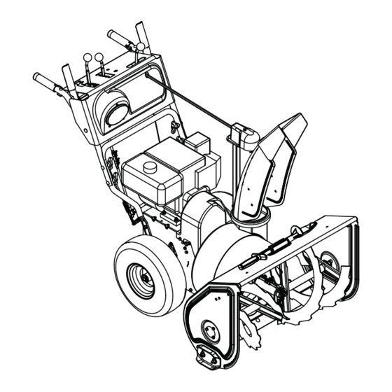
CONTROLS AND FEATURES 921005 Figure 12 1. Attachment Clutch Lever 2. Speed Selector 3. Traction Drive Clutch Lever 4. Chute Control 5. Oil Fill/Dipstick 6. Discharge Chute Deflector 7. Discharge Chute 8. Impeller 9. Clean-Out Tool 10. Auger 11. Scraper Blade 12. - Page 14 921004, 006 Figure 13 1. Attachment Clutch Lever 2. Speed Selector 3. Deflector Remote Control 4. Chute Control 5. Traction Drive Clutch Lever 6. Oil Fill/Dipstick 7. Discharge Chute Deflector 8. Discharge Chute 9. Impeller 10. Clean-Out Tool 11. Auger 12.
- Page 15 921007, 008, 009 Figure 14 1. Attachment Clutch Lever 2. Speed Selector 3. Deflector Remote Control 4. Chute Control 5. Traction Drive Clutch Lever 6. Oil Fill/Dipstick 7. Discharge Chute Deflector 8. Discharge Chute 9. Impeller 10. Clean-Out Tool 11. Auger 12.
-
Page 16: Operation
WARNING: AVOID INJURY. Read and understand the entire Safety section before proceeding. WARNING: To avoid injury to hands and feet, always disengage clutches, shut off engine, and wait for all movement to stop before unclogging or working on snow thrower. Keep hands and feet away from auger and impeller. - Page 17 Speed Selector Position the Speed Selector in the appropriate speed notch to control forward and reverse travel. Forward: (6) Fastest (1) Slowest Reverse: (1) Slow (2) Fast IMPORTANT: DO NOT change motion from forward to reverse with clutch engaged. Forward speed can be changed without declutching.
- Page 18 921005 1. Deflector Handle Figure 16 Discharge Chute Discharge chute rotates 200°. ALWAYS position discharge chute in safe direction and angle, away from operator and bystanders, before starting engine. Discharge Chute Control (921004, 006, 007, 008, 009) IMPORTANT: If chute does not stay in set position, adjust as directed in SERVICE AND ADJUSTMENTS on page 24, or repair before operation.
-
Page 19: Filling Fuel Tank
Track Angle (921007, 008, 009) (Figure 19) The track angle can be adjusted to position the auger housing for level clearing, deep cutting or transport. Squeeze the handlebar trigger and press down on the handlebars to move the auger housing into an up position. Release the trigger to hold the position. - Page 20 2. Check Function of Clutches If clutches do not engage or disengage properly, adjust or repair before operation. See Attachment Clutch/Brake Adjustment on page 28 and Traction Drive Clutch Adjustment on page 30. 3. Check Dual Handle Interlock Without the engine running, press down (engage) both clutch levers.
-
Page 21: Snow Removal
4. Make sure that the traction clutch and attachment drive clutch levers are fully disengaged. 5. Push Primer Bulb 2 or 3 times for cold engine. NOTE: When temperature is below -15° F (-26° C) additional priming may be needed. 6. -
Page 22: Maintenance
Ariens Dealers will provide any service or adjustments which may be required to keep your unit operating at peak efficiency. Should engine service be required, contact an Ariens dealer or an authorized engine manufacturer's service center. WARNING: AVOID INJURY. Read and understand the entire Safety section before proceeding. - Page 23 2. Add lubricant if required. Allow oil to drain to level of plug and replace plug. IMPORTANT: Use only Ariens special gear lubricant L-2 (Part Number 00008000). Gearcase filler plug may require an application of Loc-Tite® 565 thread sealant with repeated servicing.
-
Page 24: Service And Adjustments
IMPORTANT: DO NOT allow grease or oil to get on friction disc, friction plate or belts. NOTE: Apply Ariens Hi-Temp Grease or equivalent to the lubrication fittings. See SERVICE PARTS on page 35. Sno-Thro should be lubricated (Figure 23) at beginning of season or every 25 operating hours. -
Page 25: Deflector Remote
1. Runner 2. Runner Hardware Figure 24 SHEAR BOLTS IMPORTANT: Use only Ariens shear bolts for replacement. Use of any other type of shear bolt may result in severe damage to unit. See SERVICE PARTS on page 35. Occasionally a foreign object may enter the... -
Page 26: Discharge Chute Deflector
4. To adjust deflector higher: Slide cable up. Tighten top nut. 5. Check travel and repeat adjustment as necessary. 921004, 006, 007, 008, 009 1. Adjusting Nuts 2. Cable Support Bracket Figure 27 DISCHARGE CHUTE (921004, 006, 007, 008, 009) If chute does not stay in position while throwing snow or if chute does not rotate freely, adjust the cable under the control... -
Page 27: Speed Selector Adjustment
921005 Discharge Chute Adjusting Deflector Hardware Figure 30 DISCHARGE CHUTE (921005) If discharge chute does not stay in position while operating, tighten nut on carriage bolt at pivot point to increase tension on spring (Figure 31). 921005 OS7177 1. Spring 2. -
Page 28: Check Attachment Idler Arm Roller Clearance
ATTACHMENT CLUTCH/BRAKE ADJUSTMENT (Figures 33, 34 and 35) IMPORTANT: IMPROPER ADJUSTMENT could result in unexpected movement of auger and impeller causing death or serious injury. Auger / impeller must stop within 5 seconds when Attachment Clutch/Impeller Brake lever is released. Remove Attachment Cable Slack 1. -
Page 29: Adjust Attachment Clutch Cable Spring Extension
OS7189 Roller should be 1/2 –7/8 in. (12.7 – 22.2 mm) from the frame when the attachment clutch is engaged. Figure 35 Adjust the Attachment Clutch Cable Spring Extension 1. Check the attachment clutch cable spring extension. Measure the length of the attachment clutch cable spring with the clutch lever disengaged. -
Page 30: Traction Drive Clutch Adjustment
Check Attachment Brake See Figure 38. 1. With the clutch lever disengaged, brake pad must contact attachment belts. With clutch lever engaged, brake pad must be more than 1/16 in. (1.6 mm) from belts. If there is more than 1/16 in. (1.6 mm) gap, go to Check Belt Finger Clearance on page 30. -
Page 31: Attachment Drive Belt Replacement
a. With the traction drive clutch lever disengaged, loosen the jam nut on the cable adjuster. b. Turn the adjuster body up the cable to decrease the distance between the clutch lever and handlebar. c. Turn the adjuster body down the cable to increase the distance between the clutch lever and handlebar. -
Page 32: Traction Drive Belt Replacement
CAUTION: Always support Sno- Thro frame and blower housing when loosening the cap screws holding them together. Never loosen cap screws while unit is in service position. 8. Remove hex bolts securing housing to frame (two on each side). Tip housing and frame apart on pivot pin (Figure 43). -
Page 33: Friction Disc Replacement
2. To gain belt clearance, remove swing gate spacer and slide drive plate over so that finger clears stop hole in frame and can swing past it. See Figure 45. OS7144 1. Spacer 2. Drive Plate Assembly 3. Traction Belt Idler 4. - Page 34 OS7142 1. Hex Shaft 2. Bearing Flange 3. Speed Selector Figure 46 TRACK TENSION ADJUSTMENT (921007, 008, 009) Check the track tension by applying pressure on the track midway between the upper and rear track rollers. Deflection should be approximately 3/8 in. (9.6 mm). See Figure 47.
-
Page 35: Storage
To treat the fuel system for storage: 1. Add fuel stabilizer (Ariens p/n 00592900) according to manufacturers’ instructions. 2. Run engine for at least 10 minutes after adding stabilizer to allow it to reach the carburetor. -
Page 36: Troubleshooting
PROBLEM PROBABLE CAUSE Engine will not 1. Fuel tank is empty. crank/start. 2. Fuel shut-off valve closed. 3. Build up of dirt and residue around governor/carburetor. 4. Key Switch not in run position. 5. Electric starter not functioning. Engine stops. 1. -
Page 37: Specifications
Model Number Description Engine - Power Max - HP (kW) Fast Idle Speed - RPM (min) Displacement - in. (cc) Electric Start Fuel Tank Capacity - qt (Liters) Snow Clearing Width - in. (cm) Chute Rotation Angle Rotation Control at Handlebar Remote Deflector Control... - Page 38 Model Number Description Engine - Power Max - HP (kW) Fast Idle Speed - RPM (min) Displacement - in. (cc) Electric Start Fuel Tank Capacity - qt (Liters) Snow Clearing Width - in. (cm) Chute Rotation Angle Rotation Control at Handlebar Remote Deflector Control...
-
Page 39: Warranty
Genuine Ariens or Gravely brand service parts and accessories are warranted to be free from defects in material and workmanship for a period of 90 days after the date of purchase. An authorized Ariens dealer will repair or replace any such part or accessory free of charge, except for labor, during that period. - Page 40 Canada. In all other countries, contact place of purchase for warranty information. Disclaimer Ariens may from time to time change the design of its products. Nothing contained in this warranty shall be construed as obligating Ariens to incorporate such design changes into previously manufactured products, nor shall such changes be construed as an admission that previous designs were defective.
- Page 42 Ariens Company 655 West Ryan Street Brillion, WI 54110-1072 920-756-2141 Fax 920-756-2407 www.ariens.com...