Table of Contents
Advertisement
Quick Links
Download this manual
See also:
Manual
Advertisement
Table of Contents

Related Manuals for Planet FGSW-2402VS


Summary of Contents for Planet FGSW-2402VS
- Page 1 User's Manual FGSW-2402VS FGSW-2620VSF FGSW-2624SF 24-Port 10/100Mbps with 2-Gigabit Web Smart Ethernet Switch - 1 -...
- Page 2 PLANET has made every effort to ensure that this User’s Manual is accurate; PLANET disclaims liability for any inaccuracies or omissions that may have occurred.
-
Page 3: Table Of Contents
TABLE OF CONTENTS 1. INTRODUCTION............................5 1.1 C ................................5 HECKLIST 1.2 A ..............................5 BOUT THE WITCH 1.3 F ................................6 EATURES 1.4 S .................................6 PECIFICATION 2. HARDWARE DESCRIPTION ........................8 2.1 F ................................8 RONT ANEL 2.2 R ................................9 ANEL 2.3 H ............................10 ARDWARE NSTALLATION... - Page 4 Case 5: Deny Specify Protocol – HTTP / WWW ....................86 Case 6: Deny Specify Protocol – SMTP ......................... 88 - 4 -...
-
Page 5: Introduction
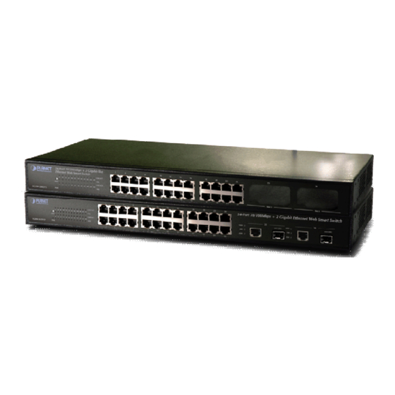
1.2 About the Switch The FGSW-2402VS offers 24 10/100Mbps Fast Ethernet ports with 2 open slots (port25, 26). The two open slots can be installed by optionally two of 1000Base-T port, 100Base-FX, or 1000Base- SX/LX fiber-optic interfaces. The distance can be extended from 100 meters (TP), 2 kilometers (Multi-mode, ST or SC), up to 15 kilometers (Single-mode, SC). -
Page 6: Features
19-inch rack mount size ◆ Internal full-range power supply suitable for worldwide use ◆ EMI standards comply with FCC, CE class A ◆ 1.4 Specification Product FGSW-2402VS FGSW-2620VSF FGSW-2624SF Hardware Specification 24 10/ 100Base-TX RJ-45 Auto-MDI/MDI-X ports 10/100Mbps Ports 24 100Base-FX 100Base-FX Ports... - Page 7 1.87kg 1.85kg 2.6kg Weight 100~240V AC, 50-60 Hz Power Requirement 5 watts (without SFP) Power Consumption / 13.5 Watts maximum / 46 BTU/hr maximum 23.1 watts maximum / 73 Dissipation Operating: 0~50 degree C, Storage -40~70 degree C Temperature 10% to 90%, Storage: 5% to 95% (Non-condensing) Humidity Operating: Smart function Web interface...
-
Page 8: Hardware Description
The Front Panel of the Web Smart Ethernet Switch consists of 24x Auto-Sensing 10/100Mbps Ethernet RJ-45 Ports, the FGSW-2402VS provide two open slots can be installed by optionally two of 1000Base-T port, 100Base-FX, or 1000Base- SX/LX fiber-optic interfaces. The FGSW-2620VSF provides 2 Gigabit TP/SFP combo ports either can be 1000Base-T for 10/100/1000Mbps or 1000Base-SX/LX through SFP (Small Factor Pluggable) interface. -
Page 9: Rear Panel
2.2 Rear Panel The rear panel of the Web Smart Switch indicates an AC inlet power socket, which accepts input power from 100 to 240VAC, 50-60Hz. Figure 2-4: FGSW-2402VS/FGSW-2620VSF Switch rear panel POWER Figure 2-5: FGSW-2624SF Switch rear panel Power Notice: 1. -
Page 10: Hardware Installation
2. In some area, installing a surge suppression device may also help to protect your Web Smart Switch from being damaged by unregulated surge or current to the Web Smart Switch. 2.3 Hardware Installation his part describes how to install your Web Smart Ethernet Switch and make connections to the Switch. Please read the following topics and perform the proce dures in the order being presented o install your Web Smart Switch on a desktop... -
Page 11: Installing The Sfp Transceiver
Figure 2-8 appears. Figure 2-8 Plug-in the SFP transceiver Approved PLANET SFP Transceivers PLANET Web Smart switches support both single mode and mu lti mode SFP transceiver. T he following list of approved LANET SFP transceivers is correct at the time of publication: ■MGB-SX SFP (1000BASE-SX SFP t... - Page 12 It recommends using PLANET SFPs on the Switch. If you insert a SFP transceiver that is not Note supported, the Switch will not recogniz e it. Before connect the other switches, workstation or Media Converter. Make sure both side of the SFP transfer are with the same media type, for example: 1000Base-SX to 1000Base-SX, 1000Bas-LX to 1000Base-LX.
-
Page 13: Switch Management
3. SWITCH MANAGEMENT This chapter describes how to manage the Web Smart Switch. Topics include: - Overview - Management method - Logging on to the Web Smart Switch 3.1 Overview The Web Smart Switch provides a user-friendly, web interface. Using this interface, you can perform various switch configuration and management activities, including: Please refer to the following Chapter 4 for the details. -
Page 14: Web Management
To modify your PC’s IP domain to the same with Web Smart Switch then use the default IP address (192.168.0.100) to remote configure Web Smart Switch through the Web interface. The following section will base on the console screens of FGSW-2620VSF, for FGSW-2402VS and FGSW-2624SF the display will be the same to FGSW-2620VSF. -
Page 15: Port Status
Figure 4-2 Web main menu screen 4.2 Port Status This section provides current status of each port from Web Smart Switch, the screen in Figure 4-3 appears and table 4-1 describes the port status object of Web Smart Switch. Figure 4-3 Port Status Web Page screen - 15 -... -
Page 16: Port Configuration
Object Description Port Indicate port 1 to port 26. Display the port Disable or Enable state of each port on Web Smart Switch. Enable Link Status The state of the link, indicating a valid link partner device. "Up" means a device is successful con- nected to the port. - Page 17 Figure 4-5 Port Configuration Web Page screen Object Description Indicate port 1 to port 26. Port Enable Per port Disable or Enable on Web Smart Switch. Per port Disable (Off) or enable (On) Auto negotiation on Web Smart Switch. Auto Spd/Dpx Adjust per port speed duplex mode on Web Smart Switch;...
-
Page 18: Trunk Configuration
4.4 Trunk configuration This function allows to configuring the trunk function. It provides up to 7 trunk groups and each trunk group provides 2 to 8 member ports. Please check the member port from “Normal” to 7 trunk groups and the screen in Figure 4-6 &... - Page 19 Figure 4-8 Trunk Configuration Web Page screen Please press “Back” for return to Trunk configuration screen for further configuration. If the member port from each trunk group is out of range or less than 2 ports than the following screen appears. Figure 4-9 Trunk Configuration Web Page screen Please press “Back”...
-
Page 20: Vlan Configuration
4.5 VLAN configuration A Virtual LAN (VLAN) is a logical network grouping that limits the broadcast domain. It allows you to isolate network traffic so only members of the VLAN receive traffic from the same VLAN members. The Web Smart Switch supports two type of VLAN configuration –... - Page 21 Figure 4-11 Port-based VLAN Setting Web Page screen Press “Relogin” to re-login the Web Smart Switch and the screen in Figure 4-12 appears. Figure 4-12 Port-based VLAN Setting Web Page screen After login web interface of Web Smart Switch and choose VLAN configuration, the screen in Figure 4-13 appears.
- Page 22 Figure 4-13 Port-based VLAN Configuration Web Page screen Press “AddNew” button to add a port-based VLAN group and setup procedure is shown as below: Input a VLAN group ID and available range is 1-4094. Select specific port as member port and the screen in Figure 4-14 appears.
- Page 23 Figure 4-14 Port-based VLAN Setting Web Page screen Figure 4-15 Port-based VLAN Setting Web Page screen - 23 -...
- Page 24 Figure 4-16 Port-based VLAN Setting Web Page screen - 24 -...
-
Page 25: Edit Existence Port-Based Vlan Group
4.5.2 Edit existence port-based VLAN group Click existence VLAN group ID to edit existence port-based VLAN group, the edit procedure is shown as below: Select specific port as member port and the screen in Figure 4-17 appears. After setup completed, please press “Apply” button to take effect and the screen in Figure 4-18 appears. -
Page 26: Delete Existence Port-Based Vlan Group
4.5.3 Delete existence port-based VLAN group The port-based VLAN group delete procedure is shown as below: Check existence VLAN group ID and the screen in Figure 4-19 appears. Press “Delete” button to delete existence port-based VLAN group. Then the “Delete all checked groups” window appears, please press “OK” to continue the delete VLAN group procedure and the screen in Figure 4-20 appears. - Page 27 Figure 4-20 Delete Port-based VLAN group Web Page screen Figure 4-21 Delete Port-based VLAN group Web Page screen - 27 -...
-
Page 28: Disable Port-Based Vlan Function
Figure 4-22 Port-based VLAN group Web Page screen 4.5.4 Disable port-based VLAN function Select “Disable” and pop window appears, press “OK” to disable the port-based VLAN function then the Web Smart Switch will reboot for take affect. The screen in Figure 4-23 &... - Page 29 Figure 4-24 Disable Port-based VLAN function Web Page screen Figure 4-25 Disable Port-based VLAN function Web Page screen - 29 -...
- Page 30 Figure 4-26 Disable Port-based VLAN function Web Page screen Figure 4-27 Disable Port-based VLAN function Web Page screen - 30 -...
-
Page 31: Enable 802.1Q Vlan Function And Add A New Vlan Group
4.5.5 Enable 802.1Q VLAN function and add a new VLAN group Select “802.1Q” and press “Apply” button, to enable the 802.1Q VLAN function then the Web Smart Switch will reboot for take affect. The screen in Figure 4-28 appears. Figure 4-28 802.1Q VLAN Setting Web Page screen Press “Relogin”... - Page 32 Figure 4-30 802.1Q VLAN Configuration Web Page screen Press “AddNew” button to add a 802.1Q VLAN group and setup procedure is shown as below: Input a VLAN group ID and available range is 1-4094. Select specific port as member port and the screen in Figure 4-31 appears.
- Page 33 Object Description You can configure the ID number of the VLAN by this item. This field is used to add VLANs one at a time. The VLAN group ID and available range is 2-4094 Port Indicate port 1 to port 26. Forbidden ports are not included in the VLAN ---------- Packets forwarded by the interface are untagged...
-
Page 34: Configure Advanced 802.1Q Vlan Setting
Figure 4-33 802.1Q VLAN Setting Web Page screen 4.5.6 Configure Advanced 802.1Q VLAN Setting Click “Advanced 802.1Q VLAN Setting” to set the per-port 802.1Q VLAN function. The screen in Figure 4-34 appears. Figure 4-34 802.1Q VLAN Setting Web Page screen - 34 -... - Page 35 Object Description Indicate port 1 to port 26. Port The frame is discarded if this port is not a member of the VLAN with which this frame is associated. In a tagged frame, the VLAN is identified by the VLAN ID in the Enabled tag.
-
Page 36: Edit Existence 802.1Q Vlan Group
4.5.7 Edit existence 802.1Q VLAN group Click existence VLAN group ID to edit existence 802.1Q VLAN group, the edit procedure is shown as below: Select specific port as member port and the screen in Figure 4-35 appears. After setup completed, please press “Apply” button to take effect and the screen in Figure 4-36 appears. -
Page 37: Delete Existence 802.1Q Vlan Group
4.5.8 Delete existence 802.1Q VLAN group The 802.1Q VLAN group delete procedure is shown as below: Check existence VLAN group ID and the screen in Figure 4-37 appears. Press “Delete” button to delete existence port-based VLAN group. Then the “Delete all checked groups” window appears, please press “OK” to continue the delete VLAN group procedure and the screen in Figure 4-38 appears. - Page 38 Figure 4-39 Delete 802.1Q VLAN group Web Page screen Figure 4-40 802.1Q VLAN group Web Page screen - 38 -...
-
Page 39: Port Monitoring
4.6 Port Monitoring This function provide to monitoring network traffic that forwards a copy of each incoming or outgoing packet from one port of a network Switch to another port where the packet can be studied. It enables the manager to keep close track of switch performance and alter it if necessary. -
Page 40: Qos Configuration
4.7 QoS Configuration This function provides QoS Configuration of Web Smart Switch, the screen in Figure 4-42 appears and table 4-4 de- scriptions the QoS Configuration of Web Smart Switch. Figure 4-42 QoS Configuration Web Page screen Object Description Provide different modes for QoS Configuration, the available options are shown as below: QoS Mode Disable QoS Priority, High Empty Then Low,... - Page 41 Figure 4-43 QoS Configuration Web Page screen Figure 4-44 QoS Configuration Web Page screen - 41 -...
- Page 42 Figure 4-45 QoS Configuration Web Page screen - 42 -...
-
Page 43: Port Counters
4.8 Port counters This function could provide you with an individual statistical counter; it is a useful page for administrator to monitor each port’s usage condition. Also, it is helpful to troubleshooting network problems. The screen in Figure 4-46 & 4-47 appears. -
Page 44: Access Control List
4.9 Access Control List The Access Control List (ACL) is a concept in computer security used to enforce privilege separation. It is a means of determining the appropriate access rights to a given object depending on certain aspects of the process that is making the request, principally the process's... - Page 45 Figure 4-49 Access Control List (ACL) Web Page screen Figure 4-50 Access Control List (ACL) Web Page screen - 45 -...
- Page 46 Figure 4-51 Access Control List (ACL) Web Page screen Figure 4-52 Access Control List (ACL) Web Page screen - 46 -...
- Page 47 Figure 4-53 Access Control List (ACL) Web Page screen Figure 4-54 Access Control List (ACL) Web Page screen - 47 -...
- Page 48 Figure 4-55 Access Control List (ACL) Web Page screen Figure 4-56 Access Control List (ACL) Web Page screen - 48 -...
- Page 49 Figure 4-57 Access Control List (ACL) Web Page screen Figure 4-58 Access Control List (ACL) Web Page screen - 49 -...
- Page 50 Figure 4-59 Access Control List (ACL) Web Page screen Figure 4-60 Access Control List (ACL) Web Page screen - 50 -...
- Page 51 Figure 4-61 Access Control List (ACL) Web Page screen Figure 4-62 Access Control List (ACL) Web Page screen For more detail information about Access Control List applications, please refer to Appendix B at page 71 - 51 -...
-
Page 52: Web Smart Function
4.10 Web Smart Function This function could provide you to define device indicate connect to each port on Web Smart Switch, the screen in Figure 4-63 appears. Figure 4-63 Web Smart Funciton Web Page screen The available options are shown as below: PC+Voip Switch Router... - Page 53 Figure 4-64 Web Smart Funciton Web Page screen Figure 4-65 Web Smart Funciton Web Page screen - 53 -...
- Page 54 Figure 4-66 Web Smart Funciton Web Page screen This function also provides Apply for all ports option from Select a port function, the setup procedure shown as below: Choose a device and check “Apply for all ports” from options of Select a port function, the screen in Figure 4-67appears.
- Page 55 Figure 4-67 Web Smart Function Web Page screen Figure 4-68 Web Smart Funciton Web Page screen - 55 -...
- Page 56 Figure 4-69 Web Smart Funciton Web Page screen Figure 4-70 Web Smart Funciton Web Page screen - 56 -...
-
Page 57: Misc Operation
4.11 Misc Operation This section provide Misc Operation of Web Smart Switch, the screen in Figure 4-71 appears and table 4-6 descriptions the Misc Operation objects of Web Smart Switch. Figure 4-71 Misc Operation Web Page screen Object Description Switch Configuration Provide Advanced Switch Configuration and available options are Broadcast Storm Filter. Collision Retry Forever. -
Page 58: Switch Configuration
4.11.1 Switch Configuration Choose Switch Configuration from Misc Operation of Web Smart Switch( please see the Figure 4-72) , the screen in Figure 4-73 appears and table 4-7 descriptions the Switch Configuration from Misc Operation of Web Smart Switch. Figure 4-72 Switch Configuration Web Page screen Object Description Provide Broadcast storm filter function and available options are Off. - Page 59 Figure 4-73 Switch Configuration Web Page screen Figure 4-74 Switch Configuration Web Page screen - 59 -...
- Page 60 Figure 4-75 Switch Configuration Web Page screen Figure 4-76 Switch Configuration Web Page screen - 60 -...
-
Page 61: Tftp Firmware Upgrade
4.11.2 TFTP Firmware Upgrade This section provides Firmware upgrade through TFTP method on Web Smart Switch, the screen in Figure 4-77 pears. Figure 4-77 TFTP Firmware Update Web Page screen - 61 -... -
Page 62: Password Setting
4.11.3 Password Setting This section provides password setting of Web Smart Switch, the screen in Figure 4-78 appears and table 4-8 descrip- tions the Password Setting. Figure 4-78 Password Setting Web Page screen Object Description Provide Password protection function”Disable” or”Enable” on Web Smart Switch; Default mode is Password Pro- tection Enable. -
Page 63: Ip Configuration
4.11.4 IP Configuration This section provides IP Configuration on Web Smart Switch; the screen in Figure 4-79 appears and tables 4-9 de- scriptions the IP Configuration. Figure 4-79 IP Configuration Web Page screen Display MAC address on Web Smart Switch. MAC Address IP Address Provide to modify IP Address on Web Smart Switch. -
Page 64: Factory Default
4.11.5 Factory Default This section provides Factory Default function on Web Smart Switch, after choose this function and the following screen appears in Figure 4-80. Please press “OK” button to take effect and the switch will reset to factory default mode and ask you to waiting rebooting around 10 sec, press “OK”... - Page 65 Figure 4-82 Factory Default Web Page screen Figure 4-83 Factory Default Web Page screen - 65 -...
-
Page 66: Reboot System
4.11.6 Reboot System This section provides Reboot function on Web Smart Switch, after choose this function and the following screen appears Figure 4-84. Please press “OK” button to take effect and the switch will reboot and ask you to waiting rebooting around 10 sec, press “OK”... - Page 67 Figure 4-86 Reboot Web Page screen Figure 4-87 Reboot Web Page screen - 67 -...
-
Page 68: System Information
4.11.7 System Information This section display system information on Web Smart Switch, after choose this function and the following screen ap- pears in Figure 4-88. Figure 4-88 System Information Web Page screen - 68 -... -
Page 69: Logout
4.12 Logout This section provide web logout function on Web Smart Switch, after choose this function and the following screen appears in Figure 4-89. Please press “OK” button to take effect and Logout pop window appears, press “OK” button to re-login the Web Smart Switch. - Page 70 Figure 4-90 Logout Web Page screen Figure 4-91 Logout Web Page screen - 70 -...
- Page 71 Figure 4-92 Logout Web Page screen - 71 -...
-
Page 72: Switch Operation
5. SWITCH OPERATION 5.1 Address Table The Switch is implemented with an address table. This address table composed of many entries. Each entry is used to store the address information of some node in network, including MAC address, port no, etc. This information comes from the learning process of Ethernet Switch. -
Page 73: Troubleshooting
Check the LNK/ACT LED on the switch Try another port on the Switch Make sure the cable is installed properly Make sure the cable is the right type Turn off the power. After a while, turn on power again. How to deal forgotten password situation of FGSW-2402VS/FGSW-2620VSF Solution:... -
Page 74: Appendix A - Networking Connection
APPENDIX A - NETWORKING CONNECTION A.1 Switch‘s RJ-45 Pin Assignments 1000Mbps, 1000Base-T Contact MDI-X BI_DA+ BI_DB+ BI_DA- BI_DB- BI_DB+ BI_DA+ BI_DC+ BI_DD+ BI_DC- BI_DD- BI_DB- BI_DA- BI_DD+ BI_DC+ BI_DD- BI_DC- 10/100Mbps, 10/100Base-TX RJ-45 Connector pin assignment MDI-X Contact Media Dependant Media Dependant Interface Interface -Cross... - Page 75 There are 8 wires on a standard UTP/STP cable and each wire is color-coded. The following shows the pin allocation and color of straight cable and crossover cable connection: Figure A-1: Straight-Through and Crossover Cable Please make sure your connected cables are with same pin assignment and color as above picture before deploying the cables into your network.
-
Page 76: Appendix B - Access Control List Application Guide
APPENDIX B - ACCESS CONTROL LIST APPLICATION GUIDE Introduction: What is Access Control List An Access Control List (ACL) consists of a set of rules which are matched sequentially against a packet. When a packet meets the match criteria of a rule, the specified rule action (Permit/Deny) is taken and the additional rules are not checked for a match. -
Page 77: Before The Acl Configure
Before the ACL Configure … Notice – It is important to set the VLAN mode to “Port-Based” or “802.1Q” VLAN before you start the ACL configure. Due to the ACL will check the VLAN ID if necessary, the VLAN mode must be set to Port-Based or 802.1Q mode. And once the VLAN mode is changed, the system has to reboot to apply the new settings. -
Page 78: Case 1: Deny Specific Source Ip Address - Host
Deny Policy Sample Case 1: Deny specific Source IP Address – Host Purpose: Verify positive and negative matches to a specific host IP address with a 32 bit mask, no matter the rule defined as permit or deny. Check for Class A,B, and C address. To set a Host as the target at this case. - Page 79 ACL Policy Entry: - 79 -...
-
Page 80: Case 2: Deny Specific Source Ip Address - Class C
Case 2: Deny specific Source IP Address – Class C Purpose: Verify a positive and negative matches to network IP address with a Class C (24 bit mask) , no matter the rule defined as permit or deny. Set Hosts within the same Class C Network domain, as the targets at this case. Once the deny policy be applied, all IP packets from the targets’... - Page 81 ACL Policy Entry: - 81 -...
-
Page 82: Case 3: Deny Ip Packets To Specific Class C Network
Case 3: Deny IP packets to specific Class C network Purpose: Verify a positive and negative matches to network IP address with a Class C (24 bit mask) , no matter the rule defined as permit or deny. Any packets pass through the switch will be dropped – if the Destination IP Addresses match specific Class Any packets pass through the switch will be forwarded –... - Page 83 ACL Policy Configuration: ACL Policy Entry: - 83 -...
-
Page 84: Case 4: Deny Specific Vlan Packets
Case 4: Deny specific VLAN packets Purpose: Verify a positive and negative matches to network IP address with a specific VLAN ID , no matter the rule defined as permit or deny. Packets with VLAN ID= specific ACL VLAN ID will be dropped. Packets with VLAN ID not match the specific ACL VLAN ID will be forwarded. - Page 85 - 85 -...
- Page 86 Case 5: Deny Specify Protocol – HTTP / WWW Purpose: Verify positive and negative matches to network IP address with a specific protocol or TCP/UDP Port number, no matter the rule defined as permit or deny. Packets with Layer 4 protocol match the specific ACL protocol will be dropped. Packets with Layer 4 protocol not match the specific ACL protocol will be forwarded.
- Page 87 ACL Policy Entry: - 87 -...
- Page 88 Case 6: Deny Specify Protocol – SMTP Purpose: SMTP packets from specific Host IP Address will be dropped. Other packets from specific Host IP Address will be forwarded. Case Design: Action DENY Match Protocol Service Type SMTP ( Port 25) Source IP Address Host Destination IP Address...
- Page 89 ACL Policy Entry: 2080-A81030-001 - 89 -...