Advertisement
Quick Links
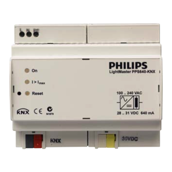
PPS640-KNX
Network Power Supply
INSTALLATION MANUAL
WARNING
ISOLATE FROM MAINS SUPPLY PRIOR
TO INSTALLATION OR SERVICING. NO USER
SERVICEABLE PARTS INSIDE. INSTALLATION
AND SERVICE BY QUALIFIED PERSONNEL
ONLY
• Risk of electric shock
• Do not cut or terminate live wires. De-energize and
isolate all supply, load and control wiring prior to
installation or servicing. Do not expose this device
to rain or moisture. The device is only suitable for
indoor installation and must be earthed. Check all
wiring terminations prior to energizing the device.
Installation, programming and maintenance must be
carried out by qualified personnel only.
• Do not connect KNX TP1 bus to mains or load
wiring.
• KNX TP1 bus is SELV (Safety Extra Low Voltage)
and it must be isolated and segregated from mains
and other wiring as per the local wiring rules and
KNX installation recommendations.
• Do not open the device.
•
•
•
Features
• Universal Supply
• Regulated KNX TP1 and Aux Supply, Output, Short Circuit protected
• DIN Rail mount enclosure for easy installation
Important Notes
Read Instructions – We recommend that you read this Instruction
Manual prior to commencement of installation.
Output – The load on this device should not exceed the specified
rating. This device should be fed via a HRC fuse or MCB.
Mounting Location – Install in a dry, well-ventilated location indoor only.
KNX Data Cable – Use approved KNX TPI data cable.
Installation – Device must be installed by KNX certified personnel
and cabled in accordance to the standards detailed on the official KNX
Associations website.
Electrical Diagram
Reset
–
KNX OUT
+
28-31VDC
–
AUX OUT
+
30VDC
Overload
On
L
N
(PE)
Supply:
100-240V
50/60Hz
1 Phase
Advertisement

Related Manuals for Philips PPS640-KNX


Summary of Contents for Philips PPS640-KNX
-
Page 1: Important Notes
PPS640-KNX Network Power Supply INSTALLATION MANUAL Features • Universal Supply • Regulated KNX TP1 and Aux Supply, Output, Short Circuit protected • DIN Rail mount enclosure for easy installation Important Notes Read Instructions – We recommend that you read this Instruction Manual prior to commencement of installation. Output – The load on this device should not exceed the specified rating. This device should be fed via a HRC fuse or MCB. Mounting Location – Install in a dry, well-ventilated location indoor only. KNX Data Cable – Use approved KNX TPI data cable. Installation – Device must be installed by KNX certified personnel and cabled in accordance to the standards detailed on the official KNX Associations website. WARNING • Electrical Diagram ISOLATE FROM MAINS SUPPLY PRIOR •... -
Page 2: Installation Steps
Wago 243 (Yellow/White) for auxiliary supply 0.6-0.8mm wire diameter single core KNX cable Warranty Policy Philips warrant to the original purchaser for a period of twenty four (24) months from the date of shipment ex-factory of the equipment that should the equipment prove defective by reason of improper workmanship or material, Philips will repair or replace the same without charge provided the equipment has not been improperly installed, operated, repaired, damaged or abused. The warranty granted herein is limited to repair or replacement only. Philips has the right to substitute any warranty item not on the current price/equipment list. As far as the law permits, Philips shall not be liable for any loss or damage caused to property or persons arising from any cause whatsoever. This warranty is subject to the return of the equipment to Philips, or the Philips authorised distributor who supplied the equipment (the ‘Supplier’), by prepaid freight within the twenty four (24) months warranty period. Where Philips, or the Supplier, agree to a site visit during the warranty period and it is found to be an operational problem, and not subject to warranty in that event, then a field service call out charge will apply. Contact Philips or the Supplier for details.