Table of Contents
Advertisement
Quick Links
Advertisement
Table of Contents

Related Manuals for Philips PDS-150e


Summary of Contents for Philips PDS-150e
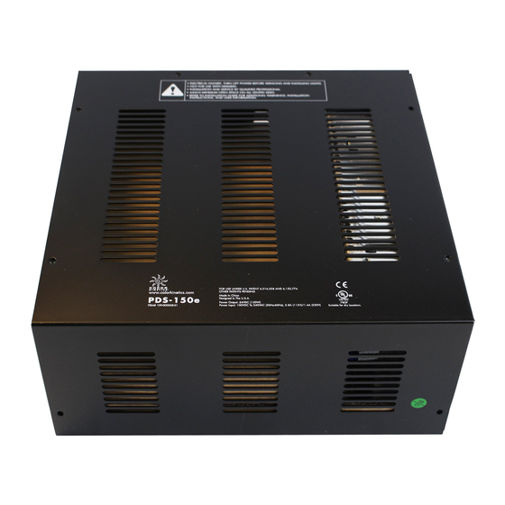
- Page 1 PDS-150e Power / data supply for Ethernet and DMX installations...
- Page 2 PDS-150e Power / data supply for Ethernet and DMX installations PDS-150e is an indoor-rated power / data supply designed for C-Splash 2, ColorBlast 6, ColorBurst 6, and ColorBlast 12 fixtures from Philips Color Kinetics. The PDS-150e is designed for use in dry locations. • Compatible with both Ethernet and DMX Compatible Fixtures controllers Max. Quantity Max. Quantity • Can accept Ethernet network data and output Fixture Per PDS-150e Per Fuse Group DMX signals to downstream devices C-Splash 2 • Short-circuit protection prevents failure due to ColorBlast 12 incorrectly wired fixtures ColorBlast 6 ColorBurst 6 • 14 pre-formed knockout holes accommodate standard US and metric conduit sizes • Built-in cooling fan and over-temperature protection circuitry prevent the PDS-150e from operating beyond its rated temperature range • Delivers 150 watts of total output via six output...
-
Page 3: Specifications
Certification UL / cUL, FCC Class A, CE, PSE, C-Tick, SAA Certification Classification UL Class 2 power supply and Safety Environment Dry Location, IP20 KiNET is the Ethernet lighting protocol from Philips Color Kinetics. .88 in 1.75 in Ordering Information (22 mm) (45 mm) Item Item Number Philips 12NC PDS-150e 109-000008-01 910503700092 Use Item Number when ordering in North America. Included in the box PDS-150e power / data supply (6) 3-pin connectors 5-pin connector (14) 6-32 x 1/4 Phillips head screws, lock washers (3) 4 amp 250 VAC fuses (spares) Cable strain relief connector (3) Push wire connectors Installation Instructions PDS-150e Product Guide... -
Page 4: Plan The Installation
Installation PDS-150e is an indoor-rated power / data supply designed for LED lighting fixtures from Philips Color Kinetics. It supports up to six fixtures and features short circuit protection and diagnostic indicators to assist with the proper operation of Philips Color Kinetics lighting systems. The PDS-150e enclosure is designed for use in dry locations. Owner / User Responsibilities It is the responsibility of the contractor, installer, purchaser, owner, and user to install, Refer to the PDS-150e Installation Instructions for specific warning and caution maintain, and operate PDS-150e in such a manner as to comply with all applicable statements. codes, state and local laws, ordinances, and regulations. Consult with the appropriate electrical inspector to ensure compliance. Plan the Installation To streamline installation and ensure accurate configuration, start with a layout or a lighting design plan that shows the physical layout of the installation and identifies the locations of all lighting fixtures, PDS-150e devices, controllers, switches, and cables. DMX and Ethernet Configurations PDS-150e can be used in either DMX or Ethernet networks. Typical DMX installations with intelligent LED fixtures from Philips Color Kinetics use a controller such as iPlayer 3, a Controller Keypad for triggering light shows and turning fixtures on and off, and one or more PDS-150e devices. PDS-150e devices can be connected in series to deliver DMX data from a single controller to all connected lights. - Page 5 Ethernet devices without a repeater. Ethernet maximum data cable length • In DMX networks, maximum data run lengths are 1000 ft (305 m). The maximum number of PDS-150e devices that can be connected in series is 32. We recommend using the on-board DMX repeater for runs of more than 32 PDS-150e PDS-150e devices connected in series. However, for run lengths of longer than Controller 1000 ft (305 m), we recommend using a third-party, commercially-available DMX repeater. 1000 ft (305 m) Max PDS-150e allows you to input Ethernet network data and output a DMX signal to downstream devices and fixtures. DMX maximum data run length Inspect PDS-150e and Accessories Included in the box Carefully inspect the box containing the PDS-150e and the contents for any damage. Assemble Additional Items PDS-150e power / data supply (6) 3-pin connectors The following additional items are required to mount and connect the PDS-150e: 5-pin connector (14) 6-32 x 1/4 Phillips head screws, lock washers • Four mounting screws suitable for the mounting surface (3) 4 amp 250 VAC fuses (spares) • The included 14 cover screws and lock washers Cable strain relief connector (3) Push wire connectors • The included six 3-pin connectors, and one 5-pin connector...
- Page 6 (257 mm) wide x 4.4 in (112 mm) high. Make sure the mounting location allows a minimum of 4 in (102 mm) around the housing, so that air can move freely around the device. Be careful not to obstruct the vents on the top or sides of the PDS- 150e housing. If the device is to be mounted on a wall, be sure that the vented sides of the device are facing up or to the side, never down. (This allows rising heat to escape from the top and sides of the unit.) When mounting PDS-150e on a wall, be sure to position the device with the conduit 5. Use four suitable mounting screws to secure PDS-150e to the mounting location. side facing the floor. This allows rising heat to escape from the housing’s top and side vents.
- Page 7 Groups A, B, C, Therefore, the maximum number of lights on ColorBlast 6 in the PDS-150e (for a total of six fixtures per CAUTION: There is one fuse per two terminal blocks any one group must be limited per PDS 150 Installation Instruction.
- Page 8 Group A Group B Group C older Philips Color Kinetics controllers. The included 5-pin connector fits into this port, CAUTION: There is one fuse per two terminal blocks denoted as Groups A, B, C,...
- Page 9 Group C Ethernet Data Input Connections CAUTION: There is one fuse per two terminal blocks denoted as Groups A, B, C, 1. Run CAT 5e or better cable from the data output port of a Philips Color Kinetics Therefore, the maximum number of lights on any one group must be limited per PDS 150 Installation Instruction.
-
Page 10: Connect To Line Power
Connect to Line Power The PDS-150e ships with the device’s line, neutral, and ground wires connected to the terminal block. You connect power to the device’s flying leads by using the included push wire connectors. 1. Install the included cable strain relief connector in one of the device’s .88 in (22 mm) openings. If necessary, use conduit as required by local electrical codes. Refer to your local electrical code for requirements for proper connection to line voltage. 2. Run the mains voltage power cable through the opening. Pull at least 6 in (152 mm) of wire into the housing. 3. Strip at least .38 in (10 mm) of insulation from the wires. Join the mains line wire with the flying leads using the included push wire connectors. .38 in 10 mm 4. If you need to assign DMX addresses your fixtures, or configure the PDS-150e over an Ethernet network, follow the steps in the Addressing and Configuration Guide prior to closing the device. Otherwise, secure the wire connections inside the housing, put the cover over the device, and use eight of the included screws and washers to close and secure the device’s cover. PDS-150e Product Guide... - Page 11 Interpreting PDS-150e Status Indicators Indicators on the right side of the circuit board provide feedback about the status of the power / data supply. Status Indicators Indicator Mode Meaning White +24 VAC of power is present on the circuit board Power Status Power +24 VAC of power is not present on the circuit board Data Blue Valid Ethernet data is being received Eth Tx Data Status Valid Ethernet data is not being received Eth Rx Fault Ethernet Tx Blue Long blink for every Ethernet packet transmitted Output Ethernet Rx Blue Long blink for every Ethernet packet received No problems Fault Indicator DMX OUT DMX IN...
-
Page 12: Replacing Fuses
6. Replace the rubber protective cover over the fuse and clips. Replace the device’s cover and secure it with the eight cover screws. Philips Color Kinetics Copyright © 2011 – 2012 Philips Solid-State Lighting Solutions, Inc. All rights reserved. 3 Burlington Woods Drive Chromacore, Chromasic, CK, the CK logo, Color Kinetics, the Color Kinetics logo, ColorBlast, Burlington, Massachusetts 01803 USA ColorBlaze, ColorBurst, eW Fuse, ColorGraze, ColorPlay, ColorReach, iW Reach, eW Reach, Tel 888.385.5742...