Advertisement
Quick Links
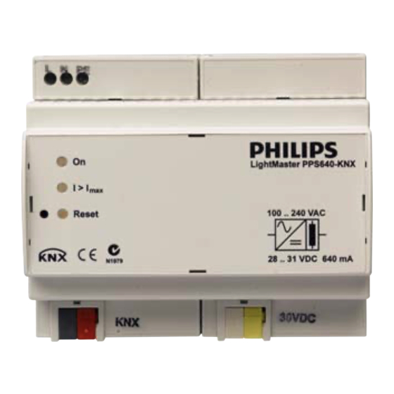
PPS640-KNX
Network Power Supply
INSTALLATION MANUAL
WARNING
ISOLATE FROM MAINS SUPPLY PRIOR
TO INSTALLATION OR SERVICING. NO USER
SERVICEABLE PARTS INSIDE. INSTALLATION
AND SERVICE BY QUALIFIED PERSONNEL
ONLY
• Risk of electric shock
• Do not cut or terminate live wires. De-energize and
isolate all supply, load and control wiring prior to
installation or servicing. Do not expose this device
to rain or moisture. The device is only suitable for
indoor installation and must be earthed. Check all
wiring terminations prior to energizing the device.
Installation a nd m aintenance m ust b e c arried o ut b y
qualified personnel only.
• Do not connect KNX TP1 bus or Aux Supply to
mains or load wiring.
• Do not connect Aux Supply to KNX TP1 bus.
• KNX TP1 bus and Aux Supply are SELV (Safety
Extra Low Voltage) and must be isolated and
segregated from mains and other wiring as
per the local wiring rules and KNX installation
recommendations.
• Do not open the device.
Features
• Universal Supply
• Regulated KNX TP1 and Aux Supply, Output Short Circuit protected
• DIN Rail mount enclosure for easy installation
Important Notes
Read Instructions – We recommend that you read this Instruction
Manual prior to commencement of installation.
Output – The load on this device should not exceed the specified
rating. This device should be fed via a HRC fuse or MCB.
Mounting L ocation – I nstall i n a d ry, w ell-ventilated l ocation i ndoor o nly.
KNX Data Cable – Use approved KNX TPI data cable.
Installation – Device must be installed by KNX certified personnel and
wired in accordance to the KNX standard and local wiring rules.
Electrical Diagram
•
•
•
28-31VDC
Reset
–
KNX OUT
+
–
AUX OUT
+
30VDC
Overload
On
L
N
(PE)
Supply:
100-240V
50/60Hz
1 Phase
Advertisement

Related Manuals for Philips PPS640-KNX


Summary of Contents for Philips PPS640-KNX
- Page 1 PPS640-KNX Network Power Supply INSTALLATION MANUAL Features • Universal Supply • Regulated KNX TP1 and Aux Supply, Output Short Circuit protected • DIN Rail mount enclosure for easy installation Important Notes Read Instructions – We recommend that you read this Instruction Manual prior to commencement of installation. Output – The load on this device should not exceed the specified rating. This device should be fed via a HRC fuse or MCB. Mounting L ocation – I nstall i n a d ry, w ell-ventilated l ocation i ndoor o nly. KNX Data Cable – Use approved KNX TPI data cable. Installation – Device must be installed by KNX certified personnel and wired in accordance to the KNX standard and local wiring rules. WARNING Electrical Diagram •...
- Page 2 PPS640-KNX Network Power Supply INSTALLATION MANUAL Installation Steps Connecting KNX Data Cabling Connect Data Cable in a Daisy Chain 1. Mount the device on a DIN rail inside an approved enclosure. 2. Connect a single phase feed to the supply terminals. This device must be earthed. 3. Connect KNX TP1 bus cables. Ensure correct cable type a nd l engths. E nsure r equired c able s egregation t o other circuits. 4. Connect Aux Supply cables if required. Ensure correct polarity and required segregation to other circuits. 5. Re-check all terminations prior to energizing and KNX Bus Permanent Connections energize the supply. 6. Check supply, KNX bus voltage and Aux supply using a multimeter. Load supply shall be within the load specification, KNX bus shall be between 21-30Vdc, Aux supply shall be between 24-30Vdc.