Table of Contents
Advertisement
Quick Links
Advertisement
Table of Contents

Related Manuals for Planet ICA-HM620


Summary of Contents for Planet ICA-HM620
- Page 1 User’s Manual ICA-HM www.PLANET.com.tw...
- Page 2 PLANET has made every effort to ensure that this User’s Manual is accurate; PLANET disclaims liability for any inaccuracies or omissions that may have occurred.
- Page 3 Trademarks The PLANET logo is a trademark of PLANET Technology. This documentation may refer to numerous hardware and software products by their trade names. In most, if not all cases, their respective companies claim these designations as trademarks or registered trademarks.
-
Page 4: Table Of Contents
TABLE OF CONTENTS Chapter 1 Introduction....................6 Overview ............................6 Product Features .......................... 6 Package Content........................... 7 Physical Details ..........................8 Camera Substance....................... 8 Switch Identification ......................8 Chapter 2 Camera Setup and Cable Connections ..........9 Physical Installation Requirement ....................9 2.1 System Requirements ...................... - Page 5 4.3.8 Application (Alarm Settings) ................52 4.3.9 Motion Detection....................60 4.3.10 Network failure detection................. 64 4.3.11 Storage Management (Local Recording)............66 4.3.12 Recording (Local Recording) ................68 4.3.13 File Locatioin..................... 69 4.3.14 View information....................70 4.3.15 Factory Default....................72 4.3.16 Software Version....................
-
Page 6: Chapter 1 Introduction
The ICA-HM620 supports removable IR-cut filter, maintaining clear images 24 hours a day. It takes surveillance using 2-Way audio so that the administrator can speak to anyone at ICA-HM620 remote site with a speaker connected. The ICA-HM620 can also be installed in most of bad outdoor environment and keep working properly with the IP-66 protecting cover. -
Page 7: Package Content
Network and Configuration IPv4/v6 and UDP / TCP / HTTP / HTTPS protocols selectable DDNS and FTP uploading supports more alternatives in surveillance network 3GPP for 3G mobile remote applications Cam Viewer Three - Central management software supported Easy configuration and management via Windows-based utility or web interface Operation Built-in 802.3at Compliant PoE Plus 360 degree continuous PAN, Tilt (-10 ~ 190 degree) -
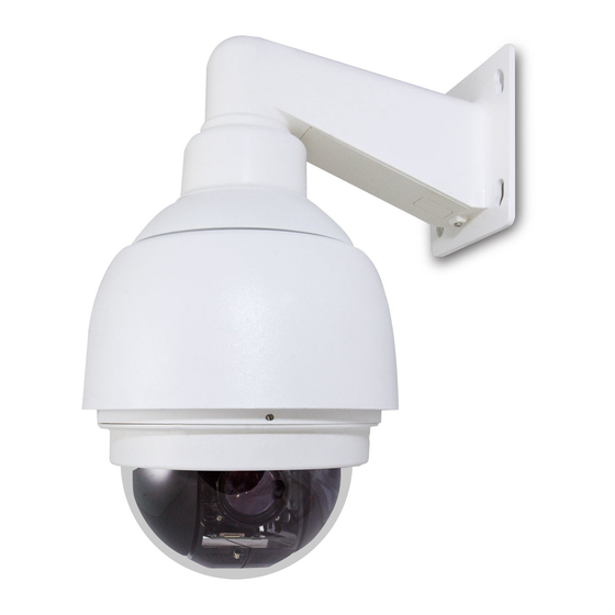
Page 8: Physical Details
Physical Details Camera Substance 1.OutdoorMount 2. Compact Pendent Mount 3. Optical Cover 4. CMOS Lens Switch Identification Item Description RJ-45 Connector ALARM I/O Power Micro SD Card Slot Factory Reset Button Audio I/O DO NOT change the Speed Dome IP Camera’s Communication Switch factory default settings. -
Page 9: Chapter 2 Camera Setup And Cable Connections
Chapter 2 Camera Setup and Cable Connections Physical Installation Requirement Before installing or connecting the dome camera, please refer to this section and complete preparations for dome setups and various switch settings. 2.1 System Requirements To perform the IP Camera via web browser, please ensure your PC is in good network connection, and meet system requirements as described below for appropriate setup and well view quality. -
Page 10: Physical Installation
Security Tool Lubricant M3/M5 Standard Screw M3/M5 Security Screw AC Power Adapter Quick Installation Guide CD-ROM Power Cord 2.3 Physical Installation 1. During the installation, please take care and avoid crash. That may cause the device damage or cause injury of the installer. Caution 2. - Page 11 STEP 2. Tighten the knob toremove the cover dome and the lens protector STEP 3. Attach the dome cover to the camera body. Before doing that, apply some lubricant on the cover’s water-proof rubber to make the installation process smoother. - 11 -...
- Page 12 The tiny protrusion on the dome cover must align with one of the four holes on the dome body. Note STEP 4. Gently pressure the dome cover downward with two hands on the side of it. DO NOT press the cover, as shown in the figure;...
- Page 13 STEP 7. Fix the Compact Pendent Mount on the wall with proper screws and screw anchors. After this step, attach the Waterproof Rubber to the Outdoor Wall Mount. STEP 8. PassRun the network and data cablespower cable through the Compact Pendent Mount 1.
- Page 14 STEP 9. Thread the cables through the Outdoor Mount Kit and join the Outdoor Mount Kit to the Compact Pendent Mount with the supplied screws and washers. Then adjust the Waterproof Rubber to the joint. Step 10 Connecting power wires of AC adapter with Power Input connector of data cable. Please check the color of power wire carefully, and screwed that with connector properly.
- Page 15 Wrong wiring could cause the device permanently damage. Caution STEP 11. Use the safety hook hanging the camera, and connect the cables to the Dome Camera. Step 12 Assemble the Dome Camera to the Outdoor Mount Kit with the supplied M5 screw and washers. - 15 -...
- Page 16 Use only the power adapter shipped with the unit to ensure correct functionality Note STEP 14. Connecting the network cable with switch. The ICA-HM620 can be configured without external power if connecting to IEEE 802.3at High Power over Ethernet (PoE plus) switch. - 16 -...
- Page 17 If there is a need to operate the Heater, please plug the AC 24V cable into the Camera’s Power Connector to power up the Camera instead. Heater can only be powered by the 24VAC adapter. Note STEP 16. Set your computer’s IP address to 192.168.0.x, where x is a number between 1 to 253 (except 20 where is being used for the camera by default).
-
Page 18: Dome Camera Setups
2.4 Dome Camera Setups Before connecting the IP Camera to other devices of IP Surveillance system, please complete the IP Camera’s ID and communication switch settings. These switches are located on the bottom of the IP Camera. 2.4.1 Switch/Connector Definition Description Item RJ-45 Connector... -
Page 19: Connect Power
2.5.1 Connect Power Please refer to the illustrations below to connect power core through the supplied power adaptor. Definition AC 24_1 AC 24_2 2.5.2 Connect Ethernet Cable Use of Category 5 Ethernet cable is recommended for network connection; to have best transmission quality, cable length shall not exceed 100 meters. - Page 20 Definition LINE_OUT LINE_IN - 20 -...
-
Page 21: Chapter 3 Accessing Camera
DeviceSearch.exe, which can be found in “DeviceSearch” folder in the supplied CD. 3.1 Device Search Software Setup Step 1: Double click on the program Planet Device Search.exe (see the icon below); its window will appear as shown below. Then click the “Device Search” button. - Page 22 in the figure below. The IP Camera’s default IP address is: 192.168.0.20. Step 4: Double click or right click and select “Browse” to access the camera directly via web browser. Step 5: Then the prompt window of request for entering default username and password (as shown below) will appear for logging in to the IP Camera.
-
Page 23: Example Of Changing Ip Camera's Network Property
Login ID Password admin admin ID and password are case sensitive. Note It is strongly advised that administrator’s password be altered for the security concerns. Refer to section Security for further details. Note Additionally, users can change the IP Camera’s network property, either DHCP or Static IP, directly in the device finding list. - Page 24 Step 3: Click “OK” on the Note of setting change. Wait for one minute to re-search the IP Camera. Step 4: Click the “Device Search” button to search all the devices. Then select the IP Camera with the correct MAC address. Double click on the IP Camera, and the login window will come out. Step 5: Enter User name and Password to access the IP Camera.
-
Page 25: Installing Dc Viewer Software Online
3.4 Installing DC Viewer Software Online For the initial access to the IP Camera, a client program, DC Viewer, will be automatically installed to your PC when connecting to the IP Camera. If the Web browser doesn’t allow DC Viewer installation, please check the Internet security settings or ActiveX controls and plug-ins settings (see Appendix B: Internet Security Settings) to continue the... -
Page 26: Administrator / User Privileges
3.5 Administrator / User Privileges “Administrator” represents the person who can configure the IP Camera and authorize user’s access to the camera; “User” refers to whoever has access to the camera with limited authority, i.e. entering Home and Camera setting pages. - 26 -... -
Page 27: Chapter 4 Configuration & Operation
Chapter 4 Configuration & Operation The IP Camera is provided with a user-friendly browser-based configuration interface, and a free bundled CV3L (Cam Viewer Three Lite Management System) for record and playback video. In this chapter, information about main page introduction, system related settings and camera settings will be described in detail. -
Page 28: Home Page
mode in this page. PTZ setting Users can adjust various camera parameters such as Exposure, White Balance, Backlight Compensation, etc., and program functions including Preset, Cruise, Auto Pan, Sequence, etc. Logout Click on the tab to re-login the IP Camera with another username and password. 4.2 Home Page On the Home Page, users can view live video and operate Pan/Tilt/Zoom (PTZ) function. - Page 29 shown in the figure below. Left click on either the “Normal View” or “Full screen” tab for setting image display mode. Pan/Tilt Control Users can implement pan/tilt control by first moving the cursor to the live video pane; then left click and drag the pointer in any direction.
- Page 30 focus near, far or automatically. Run Preset/ Cruise/ Sequence After setup the Preset/ Cruise/ Sequence lines according to PTZ Settings, select a Preset/ Cruise/ Sequence line and start it by clicking on the <Run> button ( PT Speed (1~10) Set a number between 1 and 10 as the PT Speed every time users pan or tilt the Camera via the Pan & Tilt Direction Control Panel.
- Page 31 Focus Adjustment Auto Focus (Continuous AF): Click on the “auto” button to enable AF mode. In this mode, the camera will keep in focus automatically and continuously regardless of zoom changes or any view changes. The Focus status will also be displayed above the live video pane as shown below. Manual Focus: Click on the “manual”...
-
Page 32: System Related Settings
.3 System Related Settings The figure below shows all categories un der the “System” tab. Each category in the left column will be explained in the following sections. The “System” configuration page is only accessible by the Administrator. Note - 32 -... -
Page 33: Host Name And System Time Setting
4.3.1 Host Name and System Time Setting Press the first category: <System> in the left column; the page is shown as below. Host Name The name is for camera identification. If Motion Detection function is enabled and is set to send alarm message by Mail/FTP, the host name entered here will display in the alarm message. -
Page 34: Security
shown next to the enter fields. Sync with NTP server Network Time Protocol (NTP) is an alternate way to synchronize your camera’s clock with a NTP server. Please specify the server you wish to synchronize in the enter field. Then select an update interval from the drop-down menu. - Page 35 maximum of twenty user accounts. Each user can be assigned the privileges of “Camera control” and/or “Listen”. • I/O access This item supports fundamental functions that enable users to view video when accessing to the camera. • Camera control This item allows the appointed User to change camera parameters on the Camera Setting page. •...
- Page 36 <HTTPS> allows secure connections between the IP Camera and web browser using <Secure Socket Layer (SSL)> or <Transport Layer Security (TLS)>, which ensure camera settings or Username/ Password info from snooping. It is required to install a self-signed certificate or a CA-signed certificate for implementing <HTTPS>.
- Page 37 Click on <Create> button under “Create self-signed certificate” and provide the requested information to install a self-signed certificate for the IP Camera. Please refer to the last part of this section: Provide the Certificate Information for more details. The self-signed certificate does not provide the same high level of security as when using a CA-issued certificate.
- Page 38 When the signed certificate is returned, install it by uploading the signed certificate Provide the Certificate Information To create a Self-signed HTTPS Certificate or a Certificate Request to CA, please enter the information s requested: Create Self Signed Create Certificate Request Certificate √...
- Page 39 4 . 3 .2 .3 I P F i lt er The IP Filter setting can be found under this path: System> Security> IP Filter. Using the IP filter, access to the IP Camera can be restricted by denying/allowing specific IP addresses. Enable IP Filter Check the box to enable the IP Filter function.
- Page 40 4.3.2.4 IEEE 802.1X The IEEE 802.1X setting can be found under this path: System> Security> IEEE 802.1X. The IP Camera is allowed to access a network protected by 802.1X/EAPOL (Extensible Authentication Protocol over LAN). Users need to contact with the network administrator for gaining certificates, user IDs and passwords CA Certificate The CA certificate is created by the Certification Authority for the purpose of validating...
- Page 41 Enter the user identity associated with the certificate. Up to 16 characters can be used. • Private Key Password Enter the password (maximum 16 characters) for your user identity. Enable IEEE 802.1X Check the box to enable IEEE 802.1X. Click on <Save> to save the IEEE 802.1X/ EAP- TLS setting.
-
Page 42: Network
4.3.3 Network Click <Network> in the left column, and the page will display as shown below. 4 . 3 .3 .1 B a s ic The Basic setting can be found under this path: System> Network> Basic. Users can choose to connect to the IP Camera with fixed or dynamic (DHCP) IP address. - Page 43 • Use fixed IP address To setup static IP address, select <Use fixed IP address> and move the cursor to the IP address blank and insert the new IP address, ex. 192.168.7.123; then go to the Default gateway (explained later) blank and change the setting, ex. 192.168.7.254. Press <Save>...
- Page 44 The default setting of RTSP Port is 554; the setting range is from 1024 to 65535. • MJPEG over HTTP port The default setting of MJPEG over HTTP Port is 8008; the setting range is from 1024 to 65535. • HTTPS port The default setting of HTTPS Port is 443;...
- Page 45 classified and marked with DSCP (DiffServ Codepoint) values, and thus receive the corresponding forwarding treatment from DiffServ capable routers. DSCP Settings The DSCP value range is from 0 to 63. The default DSCP value is 0, which means DSCP is disabled. The IP Camera uses the following QoS Classes: Video, Audio and Management.
- Page 46 With Simple Network Management Protocol (SNMP) support, the IP Camera can be monitored and managed remotely by the network management system. SNMP v1/ v2 • Enable SNMP v1/ v2 Select the version of SNMP to use by checking the box. •...
- Page 47 • Enable Traps Check the box to activate trap reporting. • Trap address Enter the IP address of the management server. • Trap community Enter the community to use when sending a trap message to the management system. Trap Option •...
- Page 48 When the UPnP is enabled, whenever the IP Camera is presented to the LAN, the icon of the connected IP Cameras will appear in My Network Places to allow for direct access. To enable this function, please make sure the UPnP component is installed on your computer.
-
Page 49: Ddns
4.3.4 DDNS Dynamic Domain Name System (DDNS) allows a host name to be constantly synchronized with a dynamic IP address. In other words, it allows those using a dynamic IP address to be associated to a static domain name so others can connect to it by name. Enable DDNS Check the item to enable DDNS. -
Page 50: Mail
Password Enter the password required by the DDNS provider for authentication. Example : planetddnstest01 4.3.5 Mail The Administrator can send an e-mail via Simple Mail Transfer Protocol (SMTP) when motion is detected. SMTP is a protocol for sending e-mail messages between servers. SMTP is a relatively simple, text-based protocol, where one or more recipients of a message are specified and the message text is transferred. -
Page 51: Http
4.3.7 HTTP The HTTP setting can be found under this path: System> HTTP. - 51 -... -
Page 52: Application (Alarm Settings)
A HTTP Notification server can listen for notification messages from IP Cameras by triggered events. Enter the HTTP details, which include server name (for instance, http://192.168.0.1/admin.php), user name, and password in the fields. <Alarm> triggered and <Motion Detection> notifications can be sent to the specified HTTP server. - Page 53 The Camera equips four alarm inputs and two relay outputs for cooperating with alarm system to catch events’ images. Please refer the Alarm Pin Definition as below. Definition Definition ALARM_O UT_NO_1 ALARM_OUT_COM_2 ALARM_OUT_NC_1 ALARM_OUT_COM_1 ALARM _IN_4 ALARM_IN_3 ALARM_OUT_NO_2 ALARM_IN_2 ALARM_OUT_NC_2 ALARM_IN_1 larm Pin Selection Select an alarm pin wh...
- Page 54 The specific alarm pin’s p roperty can be programmed in this section as shown below. larm Switch The Administrat or can enable or disable the alarm function. Alarm Type Select an alar m type, “Normal close” or “Normal open,” that corresponds with the alarm application. Triggered Action (Multi-option) The Administrator can specify alar m actions that will take at an alarm occurrence.
- Page 55 • Upload Image b FTP Select this item, and the Administrator can assign a FTP site and configure various parameters as shown in the figure below. When the alarm is triggered, event images will be uploaded to the appointed FTP site. •...
- Page 56 Make sure SMTP or FTP configuration has been completed. See section Mail and FTP for further details. Note • PTZ Function Assign a camera function: Preset, Sequence, Autopan or Cruise, and specify a Preset Point/Sequence Line/Autopan Path/Cruise Line for the camera to perform at an alarm occurrence. Please refer to the sections through Preset Programming to Sequence Line Programming for details of Preset Point / Sequence Line / Autopan Path / Cruise Line...
- Page 57 The dwell time is only adjustable when selecting Preset as the alarm action. When the dwell time is up, the Speed Dome IP Camera will go back to its trigger position and Note recheck alarm pin status. • Send HTTP notification Check this item, select the destination HTTP address, and specify the parameters for event notifications by <Alarm>...
- Page 58 For instance, if the custom parameter is set as” action=1&group=2”, and the HTTP server name is” http://192.168.0.1/admin.php”, notification will sent HTTP server as” http://192.168.0.1/admin.php? action=1&group=2” when alarm is triggered. • Record Stream to SD Card Select the item and the alarm-triggered recording will be saved into your Micro SD card. - 58 -...
- Page 59 Pre-trigger buffer recording function allows users to check what happened to cause the trigger. The pre-trigger buffer time range is from 1 to 3 seconds. Select <Upload for __ sec> to set the recording duration after alarm is triggered. The setting range is from 1 to 99999 seconds.
-
Page 60: Motion Detection
H: Hour, N: Minute, S: Second X: Sequence Number • Add sequence number suffix (no maximum value) File name: imageXXXXXXX.jpg X: Sequence Number • Add sequence number suffix (limited value) File Name: imageXX.jpg X: Sequence Number The file name suffix will end at the number being set. For example, if the setting is up to “10,” the file name will start from 00, end at 10, and then start all over again. - Page 61 Motion Detection function allows detecting suspicious motion and triggering alarms when motion volume in the detected area reaches/exceeds the determined sensitivity threshold value. In the Motion Detection setting page, there is a frame (Motion Detection Window) displayed on the Live View Pane. The Motion Detection Window is for defining the motion detection area. To change the size of the Motion Detection Window, move the mouse cursor to the edge of the frame and draw it outward/inward.
- Page 62 When motion is detected, the signals will be displayed on the Motion window as shown below. Detailed settings of Motion Detection are described as follows: Motion Detection You will be able to turn on/off Motion Detection in System section. Default setting is Off. Motion Detection Setting Users could adjust various parameters of Motion Detection in this section.
- Page 63 Triggered Action (Multi-option) The Administrator can specify alarm actions that will take when motion is detected. All options are listed as follows: • Enable Alarm Output 1/2 Check the item and select the predefined type of alarm output to enable alarm relay output when motion is detected.
-
Page 64: Network Failure Detection
• Send HTTP notification Check this item, select the destination HTTP address, and specify the parameters for event notifications by <Motion Detection> triggered. When an alarm is triggered, the notification can be sent to the specified HTTP server. For instance, if the custom parameter is set as” action=1&group=2”, and the HTTP server name is” http://192.168.0.1/admin.php”, notification will... - Page 65 Being capable of implementing local recording (through Micro SD card) when network failure happens, the IP Camera could be a backup recording device for the surveillance system. Detection Switch You will be able to turn on/off Network Failure Detection in System section. Default setting is Off.
-
Page 66: Storage Management (Local Recording)
Pre-trigger buffer recording function allows users to check what happened to cause the trigger. The pre-trigger buffer time range is from 1 to 3 seconds. Select <Upload for __ sec> to set the recording duration after alarm is triggered. The setting range is from 1 to 99999 seconds. Select <Upload during the trigger active>... - Page 67 Users can implement local recording to the Micro SD/SDHC card up to 32GB. This page shows the capacity information of the Micro SD card and a recording list with all the recording files saved on the memory card. Users can also format the SD card and implement automatic recording cleanup through the setting page.
-
Page 68: Recording (Local Recording)
Device information When users insert the Micro SD/SDHC card, the card information such as the memory capacity and status will be shown at Device Information section. When the memory card is successfully installed, the memory card status shall be shown at <Device information>... -
Page 69: File Locatioin
In the Recording setting page, users can specify the recording schedule that fits the present surveillance requirement. Activating Micro SD/SDHC Card Recording Two types of schedule mode are offered: Always and Time Frame setting. Users can setup the time frame to fit the recording schedule or choose <Always> to activate Micro SD/SDHC Card Recording all the time. -
Page 70: View Information
Please make sure the selected file path contains valid characters such as letters and numbers. Note 4.3.14 View information Click on the link to view the system log file. The content of the file provides useful information about configuration and connections after system boot-up. 4 . - Page 71 4 . 3 .14 . 2 View U se r I n f o rmat ion The View User Information function can be found under this path: System> View User Information. The Administrator can view each added user’s login information and privileges (refer to the section Security).
-
Page 72: Factory Default
Click on this item to view the entire system’s parameter setting. 4.3.15 Factory Default The factory default setting page is shown as below. Follow the instructions to reset the IP Camera to factory default setting if needed. Set Default Click on the “Set Default” button to recall the factory default settings. Then the system will restart in 30 - 72 -... -
Page 73: Software Version
seconds. The IP address will be restored to default. Note Reboot Click on the “Reboot” button, and the system will restart without changing current settings. 4.3.16 Software Version The current software version is displayed in the software version page, which is shown as the figure below. - Page 74 Make sure the upgrade software file is available before carrying out software upgrade. Note The procedure of software upgrade is like the following: Step 1: Click “Browse” and select the binary file to be uploaded, ex.Userland.jffs2. - 74 -...
- Page 75 Do not change the upgrade file name, or the system will fail to find the file. Note Step 2: Pull down the upgrade binary file list and select the file you want to upgrade; in this case, select “userland.jffs2.” Step 3: Press “Upgrade”. The system will first check whether the upgrade file exists or not, and then begin to upload the upgrade file.
-
Page 76: Maintenance
After the upgrade process is finished, the viewer will return to Home page. Step 4: Close the video browser. Step 5: Click “Control Panel”, and then double click “Add or Remove Programs.” In the “Currently install programs” list, select “DCViewer” and click the button “Remove” to uninstall the existing DC Viewer. -
Page 77: Video And Audio Streaming Settings
Users can export configuration files to a specified location and retrieve data by uploading an existing configuration file to the IP Camera. Export Users can save the system settings by exporting the configuration file (.bin) to a specified location for future use. - Page 78 Video Format Under Video Resolution section, the available video resolution formats are including MJPEG and H.264. Please refer to the Appendix C: Video Format for more combination details. Click on <Save> to confirm the setting. Text Overlay Settings Users can select the items to display data including date/time/text on the live video pane. The maximum length of the string is 20 alphanumeric characters.
- Page 79 To rotate the image, users can select <Flip>, for instance. Then the displayed image will be reversed as shown below. The following is descriptions for different video rotate type. • Flip If select <Flip>, the image will be rotated vertically. •...
- Page 80 Users can set the GOV length to determine the frame structure (I-frames and P-frames) in a video stream for saving bandwidth. Longer GOV means decreasing the frequency of I-frames. Click <Save> to confirm the GOV setting. H.264 Profile Users can set each H.264 Profile to <Baseline Profile>, <Main Profile> or <High Profile> according to its compression needs.
-
Page 81: Video Compression
4.4.2 Video Compression The Video Compression setting can be found under this path: Streaming> Video Compression. Users can select a proper MJPEG/H.264 compression mode on the video compression page, depending on the application. MJPEG Q (Quality) factor Higher value implies higher bit rates and higher visual quality. The default setting of MJPEG Q factor is 35;... -
Page 82: Video Ocx Protocol
Click “Save” to confirm the setting. 4.4.3 Video OCX Protocol The Video OCX Protocol setting can be found under this path: Streaming> Video OCX Protocol. In the Video OCX protocol setting page, users can select RTP over UDP, RTP over TCP, RTSP over HTTP or MJPEG over HTTP, for streaming media over the network. - Page 83 Video frame rate is for setting the frames per second (fps) if necessary. MJPEG/ H.264-1/ H.264-2/ H.264-3/ H.264-4 Frame Rate The default setting of MJPEG/H.264-1/H.264-2/ H.264-3/ H.264-4 Frame Rate is 30 fps; the setting range is from 1 to 30. Click on <Save>...
-
Page 84: Audio (Audio Mode And Bit Rate Settings)
4.4.5 Audio (Audio Mode and Bit Rate Settings) Audio Mode setting found under this path: Streaming> Audio In the Audio page, the Administrator can select one transmission mode and audio bit rate. Transmission Mode • Full-duplex (Talk and Listen simultaneously) In the Full-duplex mode, the local and remote sites can communicate with each other simultaneously, i.e. -
Page 85: Ptz Settings
4.5 PTZ Settings Under the tab <PTZ>, there are categories including: <Preset>, <Cruise>, <Auto Pan>, <Sequence>, <Home>, <Tilt Range>, <Camera- Exposure>, <Camera- WB>, <Camera- Misc1>, <Camera- Misc2>, and <Camera- Default>. 4.5.1 Preset The Preset Programming can be found under this path: PTZ> Preset. Totally 256 Preset Points can be programmed for the Speed Dome IP Camera. -
Page 86: Auto Pan
Cruise Setting To setup a Cruise Path, please first select a path number from the drop-down list. Then move the cursor to the live view pane, and move the camera to a desired view (PTZ controls) as the start point of a Cruise Path. - Page 87 Auto Pan Setting To setup an Auto Pan Path, please first select a path number from the drop-down list. Then move the cursor to the live view pane, and move the camera to a desired view as the Start Point of an Auto Pan Path.
-
Page 88: Sequence
4.5.4 Sequence The Sequence Line Programming can be found under this path: PTZ> Sequence. The Speed Dome IP Camera supports totally eight Sequence Lines; each Sequence Line consists of up to 64 Preset Points. Please refer to the instructions below to program a Sequence Line. Before setting this function, users must pre-define at least two Preset Points. - Page 89 • Sequence Line Please select the number of Sequence Line to be set from the drop-down list in the top of the Sequence setting menu. • Sequential Preset Points Setting Please setup each Preset Point of the programmed Sequence Line in order, assigning a Preset Point from the “Name”...
-
Page 90: Home
4.5.5 Home The Home Function can be found under this path: PTZ> Home. Users are able to set an operation mode to ensure constant monitoring. If the Speed Dome IP Camera idles for a period of time, the selected function will be activated automatically; this is the HOME function. The HOME function allows constant and accurate monitoring to avoid the Dome Camera idling or missing events. -
Page 91: Tilt Angle
4.5.6 Tilt Angle The Tilt Range Setting can be found under this path: PTZ> Tilt Range. The Speed Dome IP Cameras tilt angle is adjustable from minimum -10° to maximum 100°. Please enter the desired min. and max. tilt angle into the corresponding fields respectively. Press the “Set” button to save the tilt angle settings. - Page 92 The Image Flip function (see section 4.5.10 Camera—Miscellaneous Setups Menu 1) and the Image Inverse function (see section 4.5.11 Camera—Miscellaneous Setups Menu 2) Note will be disabled automatically while the Privacy Mask function is enabled. Mask Setting • Activate/Disable Privacy Mask Function The Privacy Mask function can be activated or disabled.
-
Page 93: Camera - Exposure
Mask Clearing In this section, users can delete an existing Privacy Mask. Please select the Privacy Mask to be removed from the drop-down list, and press the button “Clear”. Then the selected Privacy Mask will readily disappear. 4.5.8 Camera - Exposure In the Exposure Mode setting page, users can select either the “Full Auto”... - Page 94 source, for calculating all the other colors. The unit for measuring this ratio is in degree Kelvin (K). Users can select one of the White Balance Control modes according to the operating environment. The following table shows the color temperature of some light sources for reference. Light Sources Color Temperature in K Cloudy Sky...
-
Page 95: Camera - Miscellaneous Setups Menu 1
4.5.10 Camera - Miscellaneous Setups Menu 1 The Miscellaneous Setting Menu 1 can be found under this path: PTZ> Camera- Misc 1. In the Camera—Misc (Miscellaneous) Setups Menu 1, users can set various camera parameters including Backlight Compensation (BLC), Sharpness, Exposures Compensation (ExpComp), Image Flip, Speed by Zoom and ICR function. -
Page 96: Camera - Miscellaneous Setups Menu 2
To make the Dome Camera tilt between a specific range, such as -10° to +100° or -10° ~ +190°, please go to the Tilt Range setting page to set the tilt angle range. Otherwise, the Note Dome Camera will tilt 90° as the default setting. •... -
Page 97: Camera - Default
The WDR function is especially effective in environment with extreme contrast. Press the button “Set” when finishing the setting. Auto Calibration With the Auto Calibration function, the Speed Dome IP Camera calibrates when the deviation of dome pivot is detected. Press the button “Set” when finishing setting. 2DNR With the 2D Noise Reduction function, the processor analyzes pixel by pixel and frame by frame to eliminate environmental noise signal so that the highest quality image can be produced even in low... -
Page 98: Logout
4.6 Logout Press the tab “Logout” in the top of the page, and the login window will pop up. This enables login with another user name. - 98 -... -
Page 99: Appendix A: Ip Camera Specifications
Appendix A: IP Camera Specifications Product ICA-HM620 Camera Image Sensor 2.8” Sony Progressive Scan CMOS Sensor Lens f =4.7~84.6mm / F=1.6 Min Illumination 0.04 Lux (B/W) / 0.3 Lux (color) Optical Zoom Digital Zoom 1~8x variable Focal Length 4.7~94 mm... - Page 100 Management Web, CV3P, CV3L Operation Pan Degree 0 ~ 360 Degree continuous panning Tilt Degree -10 ~ 190 Degree Manual Speed 0.5 ~ 90 Degree / s Preset Point Preset Accuracy 0.225 Degree Preset Speed 5~400 Degree / s Sequence Auto Pan Camera Cruise Privacy Mask...
-
Page 101: Appendix B: Internet Security Settings
Appendix B: Internet Security Settings If ActiveX control installation is blocked, please either set Internet security level to default or change ActiveX controls and plug-ins settings. Internet Security Level: Default Step 1: Start the Internet Explorer (IE). Step 2: Select <Tools> from the main menu of the browser. Then Click <Internet Options>. Step 3: Click the <Security>... - Page 102 ActiveX Controls and Plug-ins Settings Refer to the previous section above. Step 1~3: Step 4: Down the page, press “Custom Level” (see the figure below) to change ActiveX controls and plug-ins settings. The Security Settings screen is displayed as below: - 102 -...
- Page 103 Step 5: Under “ActiveX controls and plug-ins”, set ALL items (as listed below) to <Enable> or <Prompt>. ActiveX controls and plug-ins settings: 1. Automatic prompting for ActiveX controls 2. Binary and scrip behaviors 3. Download signed ActiveX controls 4. Download using ActiveX controls 5.
-
Page 104: Appendix C: Video Format
Appendix C: Video Format Under Video Resolution section, select a preferred resolution setting. The available Video Resolution for MJPEG & H.264 format includes: MJPEG+ H.264 H.264 MJPEG 720 x 480 (30fps)* 1920 x 1080 (30fps) 640 x 480 (30fps) 352 x 240 (30fps) 1920 x 1080 (15fps) 1280 x 1024 (30fps) 1920 x 1080 (15fps) - Page 105 640 x 480 (30fps) 640 x 480 (30fps) 352 x 240 (30fps) H.264 + H.264 H.264-1 H.264-2 720 x 480 (30fps)* 1920 x 1080 (30fps) 640 x 480 (30fps) 352 x 240 (30fps) 1920 x 1080 (15fps) 1280 x 1024 (30fps) 1920 x 1080 (15fps) 1280 x 720 (30fps) 1024 x 768 (30fps)
- Page 106 640 x 480 (30fps) 640 x 480 (30fps) 352 x 240 (30fps) MJPEG ONLY MJPEG 1920 x 1080 (30fps) 1280 x 1024 (30fps) 1280 x 720 (30fps) 1024 x 768 (30fps) 800 x 600 (30fps) 720 x 480 (30fps) 640 x 480 (30fps) H.264 ONLY H.264 1920 x 1080 (30fps)
-
Page 107: Appendix D: Dc Viewer Download Procedure
Appendix D: DC Viewer Download Procedure The procedure of DC Viewer software download is specified as follows. Step 1: In the DC Viewer installation page, click “Next” for starting installing. Step 2: Setup starts. Please wait for a while until the loading bar runs out. - 107 -... - Page 108 Step 3: Click “Finish” to close the DC Viewer installation page. Then, the IP Camera’s Home page will display as follows: - 108 -...
-
Page 109: Appendix E: Frequently Asked Questions
Ans: [ICA-HM620] After upgraded firmware, why can’t see the picture for MJPEG video format via web browser? That because the system with the newer video formats, and the PC need to install the newer DC Viewer software to appear the video on PC properly.