
Related Manuals for Fisher PCG-06


Summary of Contents for Fisher PCG-06
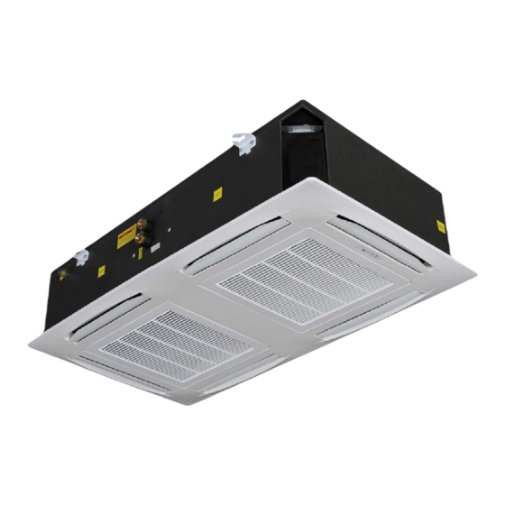
- Page 1 INSTALLATION OPERATION AND SERVICE MANUAL PCG – PS SERIES 4 PIPE HYDRONIC CASSETTE AIR CONDITIONERS 2010 V.1.0...
- Page 2 INVESTING IN QUALITY, RELIABILITY & PERFORMANCE. World Leading Design and Technology ISO 9001 QUALITY Equipped with the latest CAD/CAM computer aided design Every product is and manufacturing technology, our factories in China and manufactured to meet the Thailand produce over 2,000,000 air conditioning units each stringent requirements of year, all conforming to the highest international standards of the internationally...
-
Page 3: Table Of Contents
HYDRONIC CASSETTE INDEX PCG-PS SERIES 4 PIPE HYDRONIC CASSETTES PAGE CASSETTE MODEL ASSIGNMENTS SPECIFICATIONS a) COIL DATA b) COOLING CAPACITY TABLES c) ETHYLENE GLYCOL SOLUTIONS d) HEATING CAPACITY TABLE 11-13 INSTALLATION MANUAL 14-36 SAFETY CONSIDERATIONS OPERATING LIMITS BEFORE INSTALLATION SELECT LOCATION INSTALLATION LOCATION INSTALLATION METHOD OPENING DIMENSIONS AND POSITIONS FOR SUSPENSION BOLTS... - Page 4 HYDRONIC CASSETTE CASSETTE MODEL ASSIGNMENTS P C G - 0 6 - P 230V/1PH/50HZ CHILLED/HOT WATER, 4-PIPE NOMINAL 3.24 KW NOMINAL 3.60 KW NOMINAL 4.15 KW NOMINAL 5.10 KW NOMINAL 5.90 KW HYDRONIC CASSETTE G SERIES...
- Page 5 HYDRONIC CASSETTE PCG – PS (4-PIPE) SERIES 3-SPEED SPECIFICATIONS PCG-06 PCG-08 PCG-09 PCG-12 PCG-16 Model Number Of Fan Blowers Single Single Twin Twin Twin 1098 1296 1650 1176 1300 Total flow 1098 1100 3.24 3.60 4.15 5.10 5.90 2.86 3.02 3.23...
- Page 6 HYDRONIC CASSETTE PCG – PS (4-PIPE) SERIES 5-SPEED SPECIFICATIONS PCG-06 PCG-08 PCG-09 PCG-12 PCG-16 Model Number Of Fan Blowers Single Single Twin Twin Twin 1080 1350 1650 1236 1350 Total flow 1140 1236 1140 3.02 3.60 4.24 5.00 5.98 2.86 3.02...
-
Page 7: Cooling Capacity Tables
Fin Height Fin Length (mm.) Fins per No. of No. of Tube Model (mm) inch rows circuits Diameter Inner Outer PCG-06-08-PS 1176 1277 3/8” PCG-09-PS 2148 2286 3/8” PCG-12-16-PS 2148 2286 3/8” COIL DATA - HEATING Fin Height Fin Length (mm.) Fins per No. - Page 8 HYDRONIC CASSETTE PCG-08-PS TAI DB24℃-WB17.4℃ TAI DB27℃-WB19℃ TAI DB27℃-WB19.5℃ TAI DB28℃-WB21 Taw dPw Taw dPw °C m3/h °C °C °C °C °C °C °C °C 2.69 14.3 12.5 15.4 4.92 3.29 15.1 12.7 25.6 5.45 3.28 15.3 12.7 31.1 6.62 3.35 15.8 12.9...
- Page 9 HYDRONIC CASSETTE PCG-12-PS TAI DB24℃-WB17.4℃ TAI DB27℃-WB19℃ TAI DB27℃-WB19.5℃ TAI DB28℃-WB21 Taw dPw Taw dPw °C m3/h °C °C °C °C °C °C °C °C 1296 5.25 4.08 15.2 13.3 23.7 7.42 5.04 16.1 13.4 44.2 1311 8.05 4.94 16.3 13.5 50.9 1423...
- Page 10 HYDRONIC CASSETTE ETHYLENE GLYCOL SOLUTIONS Adding Ethylene Glycol to the water system so as to multiply the performance figures by the values given in the following table. Freezing point (℃) Percentage of ethylene glycol in weight 0.985 0.98 0.974 0.97 0.965 1.02 1.04...
-
Page 11: Heating Capacity Tables
HYDRONIC CASSETTE HEATING CAPACITY TABLES TAI 18℃ TAI 20℃ TAI 22℃ PCG-06-PS TAI 24℃ °C °C m3/h °C °C °C °C 2.28 27.4 2.36 2.07 28.5 1.98 1.86 29.6 1.64 1.65 30.7 2.12 1.92 29.1 1.74 1.73 30.2 1.44 1.54 31.3... - Page 12 HYDRONIC CASSETTE TAI 18℃ TAI 20℃ TAI 22℃ TAI 24℃ PCG-09-PS °C °C m3/h °C °C °C °C 1098 4.22 29.8 723.4 15.3 3.86 30.8 661.7 13.1 3.47 31.7 10.7 3.08 32.6 526.3 3.78 30.9 12.6 3.42 31.7 586.2 10.4 3.09 32.6 2.76...
- Page 13 HYDRONIC CASSETTE TAI 18℃ TAI 20℃ TAI 22℃ TAI 24℃ PCG-16-PS °C °C m3/h °C °C °C °C 1650 4.96 20.3 4.57 28.3 17.7 4.08 29.4 14.3 3.59 30.5 10.9 1300 16.4 4.02 29.2 3.62 30.3 11.6 3.22 31.4 1100 3.75 29.4 642.8...
-
Page 14: Safety Considerations
HYDRONIC CASSETTE THE INSTALLATION MANUAL HOT & CHILLED WATER SYSTEM AIR CONDITIONERS First check the contents of the package. FACTORY SUPPLIED ACCESSORIES Check to ensure all factory supplied accessories are supplied with the unit. FACTORY SUPPLIED ACCESSORIES AMOUNT LCD Remote control Mounting Bracket (Already on the unit) Installation manual Batteries... -
Page 15: Before Installation
HYDRONIC CASSETTE BEFORE INSTALLATION The installation site must be established by the system designer or other qualified professional, taking account of the technical requisites and current standards and legislation. PCG fan coils must be installed by an authorized company only. PCG fan coils are designed for installation in a false ceiling, for intake of fresh air from outside and for deviation of a small part of the treated air for discharge in a neighboring room. -
Page 16: Installation Location
Check the distance between the upper slab and false ceiling to ensure the unit will suit the distance. See Fig.4 Fig.4 Model A (mm.) B (mm.) PCG-09 10 or more PCG-06/08/12/16 10 or more Fig.5 Ensure there is sufficient space around the unit to service it. See Fig.5... -
Page 17: Installation Method
Using the installation template open ceiling panels and install the suspension bolts as in Fig.6 below 600 x 600: Dimensions for opening 632 x 280: Suspension Bolts MODELS PCG-06/08 600 x 1160: Dimensions for opening 750 x 632: Suspension Bolts MODELS PCG-09/12/16 FIG. -
Page 18: Opening Dimensions And Positions For Suspension Bolts
HYDRONIC CASSETTE OPENING DIMENSIONS AND POSITIONS FOR SUSPENSION BOLTS Mark position of suspension rods, water lines and condensate drain pipe, power supply cables and remote control cable. Supporting rods can be fixed, depending on the type of ceiling, as shown in Fig. 7 and Fig.8. Fit suspension brackets supplied with the unit to the threaded rods (Fig.9). - Page 19 HYDRONIC CASSETTE 12. After connection of the condensate drain piping and piping connections, check again that the unit is level. Fig. 10 Fig. 11 Fig. 12 MODEL PCG-06/08 A (mm.)
- Page 20 HYDRONIC CASSETTE Fig. 13 Fig. 14 Fig. 15 MODEL PCG-09/12/16 A (mm.) 13. The spaces between the unit and ceiling can now be adjusted. Use the drop rods to make the adjustment. 14. Check to ensure the unit is level. The drain will then automatically be lower than the rest of the drip tray.
-
Page 21: Drain Pipe Work
There are two types of valve configuration for PCG cassette: a) Internal integrated valve and b) external valve – a) Pre-installed 2-way and 3-way integrated valves (Fig. 17) Fig. 17 Integrated valve information Model Type inch PCG-06/08 2-way & 3-way 1/2” PCG-09/12/16 2-way & 3-way 3/4” (please refer to “VALVE INFORMATION”) - Page 22 HYDRONIC CASSETTE b) External valves Replace integrated valve with plug-and-play replacement connector Fig. 18 Procedures: 1) Before connecting water supply to the PCG cassette. First remove the integrated valve using spanner 2) Replace with plug-and-play connector (Fig. 18) 3) Connect the external valve directly onto the cassette. Disable integrated valve functionality using valve cap Procedures: 1) Remove integrated valve actuator by pressing on both sides.
-
Page 23: External Drain Pan
HYDRONIC CASSETTE EXTERNAL DRAIN PAN Procedures: Align the two (2) screw holes in the fixing plate to the two (2) holes in the external drain pan. (Fig. 21) Make sure the drain pan is horizontal. Tighten the two screws and making sure the external drain pan is installed flush with the fixing plate. -
Page 24: Branch Duct Connection
HYDRONIC CASSETTE Fig. 24 Fig. 25 BRANCH DUCT CONNECTION The side opening allows separate ductwork to be installed for branch ducting. (Fig. 26) Cut and remove anti-condensate insulating material. Install your flanges and conduits to casing. Conduit can be flexible polyester with spring core or corrugated aluminium externally coated (dia.4 in.) with anti-condensate material (fiberglass 12-25 mm thickness). - Page 25 HYDRONIC CASSETTE Look for the yellow sticker on the casing for location of branch duct or fresh air intake connections. BRANCH DUCT INSTALLATION The sticker is at the center of a knock out hole underneath the casing insulation. Use a cutter and follow along the pre-cut circular marking as shown and trim off the insulation.
-
Page 26: Interconnecting Wiring
HYDRONIC CASSETTE INTERCONNECTING WIRING We recommend that screened cable be used in electrically noisy areas. Always separate low voltage (5VDC) signal wires from power line (230 VAC) to avoid electro- magnetic disturbance of control system. Do not install the unit where electromagnetic waves are directly radiated at the infra red receiver on the unit. - Page 27 HYDRONIC CASSETTE CONTORL BOX CONFIGURAITON Plug-and-play control box with full functionality PCB (please refer to wiring diagram on page 60) The PCB is a universal type with multiple configurations selectable using dipswitches. Please provide dip-switch setting according to below. There are 2 DIP Switch sets on the PCB, one with 8 Dip-switches which named as DIP-Switch A and one with 6 Dip-switches which named as DIP-Switch B For master-slave connection setting, please refer to Appendix I.
-
Page 28: Mounting Front Panel Assembly
Tighten 4 screws as shown in Fig 28,29 Fig.28 Fig.29 FILTER REMOVAL Unlock the two fasteners on the front panel. Open the grille downward with care. Pull the filter out along the slot. Clean the filter and reassemble. PCG-06/08 PCG-09/12/16... -
Page 29: Maintenance
HYDRONIC CASSETTE PRELIMINARY CHECKS BEFORE START-UP The unit should not be started up until the system piping has been cleaned and all the air has been purged. Check condensate drain pipe slope. After you have connected the main power supply to the cassette unit, it is necessary to check the good function of the condensate water pump which is installed inside. -
Page 30: How To Access Air Vent And Water Purge
HYDRONIC CASSETTE HOW TO ACCESS AIR VENT AND WATER PURGE STEP: release the air vent / water purge STEP: remove the grill, air vent and water purge by loosen the screws. are located at the pointed area. HOW TO CONNECT NON-DEFAULT FAN SPEED STEP: remove the grill. - Page 31 HYDRONIC CASSETTE STEP: change the fan speed wiring according to below wiring diagram...
-
Page 32: How To Fix The Motor And Fan Blower
HYDRONIC CASSETTE HOW TO FIX THE MOTOR AND FAN BLOWER STEP: remove the grill. STEP: remove the finger guard by removing 4 screws. STEP: remove the finger guard and Venturi STEP: remove fan blower using a spanner STEP: remove the motor by removing 4 bolts and disconnect fan motor wire connector. -
Page 33: How To Fix Condensate Pump And Internal Valve
HYDRONIC CASSETTE HOW TO FIX CONDENSATE PUMP AND INTERNAL VALVE STEP: remove the grill. STEP: remove the front panel by removing 4 screws. STEP: remove the front panel by disconnecting STEP: removing the drain pan fixture by stepping motor and IR receiver. removing 8 screws. -
Page 34: How To Fix Control Box
HYDRONIC CASSETTE HOW TO FIX CONTROL BOX STEP: remove the grill. STEP: remove the front panel by removing 4 screws. STEP: remove the front panel by disconnecting STEP: remove 2 screws on the control box. stepping motor and IR receiver. STEP: Remove the terminal cover by removing 4 screws and unplug the wiring on the terminal. -
Page 35: How To Install Electric Heater
HYDRONIC CASSETTE HOW TO INSTALL ELECTRIC HEATER STEP: remove the grill. STEP: remove the front panel by removing 4 screws. STEP: remove the drain pan fixture by removing 8 STEP: remove the front panel by screws. disconnecting stepping motor and IR receiver. STEP: remove internal drain pan fixture and STEP: slide in the insulated ring of the electric internal drain pan... - Page 36 HYDRONIC CASSETTE STEP: Plug in the electric heater wiring to the STEP: slide in the rest insulated rings of the connector shown above. electric heater to the electric heater mounting shown above...
- Page 37 HYDRONIC CASSETTE EXPLODED VIEW DRAWING PCG-06 08-PS 01---casing 08-05---main PCB 02---3-way 4-ports valve (optional) G3/4 08-05-01---chilled water coil temperature sensor 03---mounting brackets 08-05-02---hot water coil temperature sensor 04---fresh air flange (optional) 08-05-03---room temperature sensor 05---Condensate water pump 09---motor with capacitor...
- Page 38 HYDRONIC CASSETTE PCG-09 16-PS 01---casing 08-05---main PCB 02---3-way 4-ports valve (optional) G3/4 08-05-01---chilled water coil temperature sensor 03---mounting brackets 08-05-02---hot water coil temperature sensor 04---fresh air flange (optional) 08-05-03---room temperature sensor 05---Condensate water pump 09---motor with capacitor 05-01---pump body 10---electrical heater (optional) 05-02---float switch 11---fan blower 05-03---flexible hose 1...
-
Page 39: Dimensional Drawings
HYDRONIC CASSETTE DIMENSIONAL DRAWINGS PCG-06-08-PS... - Page 40 HYDRONIC CASSETTE PCG-09-PS...
- Page 41 HYDRONIC CASSETTE PCG-12/16-PS...
- Page 42 HYDRONIC CASSETTE VALVE INFORMATION...
- Page 43 HYDRONIC CASSETTE...
- Page 44 HYDRONIC CASSETTE REMOTE CONTROL HANDSET WIRELESS LCD HANDSET DISPLAY...
- Page 45 HYDRONIC CASSETTE ***When unit with handset is master, settings are automatically sent to slaves; ***Auto Cool-Heat operation will be applicable in 4-pipe system only. ***Swing is not applicable to PCG models.
- Page 46 HYDRONIC CASSETTE ***Wall pad will recognize the main board model automatically whether it is 2 pipes or 4 pipes. Auto Cool-Heat operation will be applicable in 4 pipe system only. ***When the wall pad is connected to the main board, air sensor inside the wall pad will be automatically set as primary source and the return air sensor from the unit will be disabled.
- Page 47 HYDRONIC CASSETTE WALL PAD OPERATION 1) Clock display and setting System has an accurate internal real time clock used for time indication and timer ON/OFF function. TIME Real time clock display area indicates internal time clock which can be set by button.
- Page 48 HYDRONIC CASSETTE TIMER 3. Press button again to enter into off timer programming mode. Press button to select the required day of the week. Master unit will then retrieve the setting from the selected slave unit and timer display area will show “rEAd”. The off timer setting will be TIME shown upon reading the data successfully.
- Page 49 HYDRONIC CASSETTE 11) Networking Master - Slave control (only master unit wall pad can control other units on the network) Press button to enter into networking control mode. Unit area blinking indicates the slave unit TIME under control. Press to select the desired slave unit; Units that are off will be bypassed TIME automatically.
-
Page 50: Control Specifications
HYDRONIC CASSETTE CONTROL SPECIFICATIONS HOT AND CHILLED WATER CASSETTE WITH MASTER-SLAVE CONTROL 1. ABBREVIATIONS AND DEFINITION OF INPUT & OUTPUT PORTS Ts = Setting temperature Tr = Room air temperature Ti1 = Indoor coil temperature, ID1 Ti2 = Indoor coil temperature, ID2 MTV1 = Cool Motorized valve MTV2 = Heat Motorized valve AUX1 = Hot water free contact... - Page 51 HYDRONIC CASSETTE High fan speed Max length: 5 m. Voltage output (L) Medium fan speed Max length: 5 m. Voltage output (L) Low fan speed Max length: 5 m. Voltage output (L) Water valve Chilled water valve Valve1 MTV1 Voltage output Voltage output (L) Voltage output (L) Hot water valve...
- Page 52 HYDRONIC CASSETTE HEAT MODE HEAT MODE--- WITHOUT ELECTRICAL HEATER MTV1, AUX2 and heater always off. If Tr <= Ts﹣1 ºC (or -4 ºC if economy contact is activated), heat operation is activated, MTV2 and AUX1 are turned on. Indoor fan runs at the set speed. If Tr >Ts, heat operation is terminated, MTV2 and AUX1 are turned off.
- Page 53 HYDRONIC CASSETTE DEHUMIDIFICATION MODE MTV2, AUX1 and heater always off. If Tr >= 25 ºC, MTV1 and AUX2 will be ON for 3 minutes, and OFF for 4 minutes. If 16 ºC < =Tr < 25 ºC, MTV1 and AUX2 will be ON for 3 minutes, and OFF for 6 minutes. If Tr <16 ºC, MTV1 and AUX2 will be turned off for 4 minutes.
- Page 54 HYDRONIC CASSETTE AUTO FAN SPEED In cool mode, the fan speed cannot change until it has run at this speed for more then 30 seconds. Fan speed is regulated according to the profile below. High Ts+3C High Medium Ts+2C Medium Ts+1C In heat mode, the fan speed cannot change until it has run at this speed for more then 30 seconds.
- Page 55 HYDRONIC CASSETTE BUZZER If a command is received by the air conditioner, the master unit will respond with 2 beeps for each setting, and the slave unit will respond with 1 beep. AUTO RESTART The system uses non-volatile memory to save the present operation parameters when system is turned off or in case of system failure or cessation of power supply.
-
Page 56: Error Description
HYDRONIC CASSETTE ERROR DESCRIPTION LED lights Indication - with Master-Slave Connection For unit with handset only Error message can be found in LED lights on unit body. Table below indicate the error code for master and all slave unit. Table 1 For all units (both master and slave) High speed Red LED On... - Page 57 HYDRONIC CASSETTE For unit with wall pad only Error message can be found in both LED lights on unit body (please refer to table 1) and wall pad error indication. (Please refer to page 49 Error Indication) Note: If the address of slave unit is not set (refer to appendix I) LED lights and Wall pad of the master unit will not show the status of the defective slave unit.
- Page 58 HYDRONIC CASSETTE SENSOR RESISTANCE R-T CONVERSION TABLE R25: 10KΩ±1% B25/85: 3977±1% Rmin Rnom Rmax Rmin Rnom Rmax (℃) (KΩ) (KΩ) (KΩ) (℃) (KΩ) (KΩ) (KΩ) 182.7 191.8 26.11 26.9 27.71 163.4 171.5 179.9 24.85 25.59 26.34 153.6 161.1 168.9 23.65 24.35 25.05 144.4...
- Page 59 HYDRONIC CASSETTE R25: 10KΩ±1% B25/85: 3977±1% Rmin Rnom Rmax Rmin Rnom Rmax (℃) (KΩ) (KΩ) (KΩ) (℃) (KΩ) (KΩ) (KΩ) 5.614 5.759 5.907 1.417 1.474 1.532 5.387 5.53 5.673 1.37 1.426 1.482 5.172 5.31 5.451 1.326 1.379 1.434 4.966 5.101 5.238 1.282 1.335...
- Page 60 HYDRONIC CASSETTE CONTROL AND POWER SUPPLY WIRING DIAGRAMS...
- Page 61 HYDRONIC CASSETTE MASTER-SLAVE CONTROL WIRING DIAGRAM...
- Page 62 HYDRONIC CASSETTE MALFUNCTION CAUSE REMEDY - Check for presence of The fan coil does No voltage voltage not start up - Place in the “ON” position Mains switch in the “OFF - Check the room control Faulty room control - Check fan motor Faulty fan Insufficient output Filter clogged...
- Page 63 HYDRONIC CASSETTE Appendix I MASTER AND SLAVE UNIT FUNCTION The control PCB can be set either as a master unit or slave unit. 2.A.1 MASTER UNIT FUNCTION a) The master unit sends data on its setting to the slave unit. b) The master unit settings are Unit ON/OFF, Mode, Fan Speed, Set Temperature, Swing Function, and Sleep Function for handset operation.
- Page 64 HYDRONIC CASSETTE 2.A.4 MASTER-SLAVE CONFIGURATION Master unit: close SW6 [DIP switch] before power on. Master will beep twice to the LCD wireless handset or LCD wall pad confirming receipt of commands. Each master can command up to 31 slave units. Slave unit: open SW6 [DIP switch] before power on.
- Page 65 HYDRONIC CASSETTE Slave Slave Slave Slave Slave Slave Slave Slave Slave Slave Slave Slave Slave Slave Slave...
- Page 66 HYDRONIC CASSETTE...