
Related Manuals for Husqvarna TC - TE 449 2013 I.E.


Summary of Contents for Husqvarna TC - TE 449 2013 I.E.
- Page 1 TC - TE 449 2013 I.E. TE - TXC 511 2013 I. E. SPECIFICATIONS - OPERATION - MAINTENANCE EN - 1 Ed. 03-2012 - Rev. 00 Unless specified, data and prescription are referred to all the models.
- Page 2 SUMMARY Note Page References to the “left” or “right” of the motorcycle are PRESENTATION ............3 considered from the point of view of a person facing forward. IMPORTANT NOTICES............3 INTENDED USE .............4 number of teeth IDENTIFICATION DATA ..........5 l A: Austria TECHNICAL DATA ............6 AUS: Australia...
- Page 3 1) TC - TXC models are designed for RACING use, and guar- are excluded from the warranty. Your new Husqvarna motorcycle is designed and man- anteed free from operating faults; the recommended mainte- ufactured to be the best in its field. The instructions in nance table for racing use can be found in Appendix A.
- Page 4 Note*: Gives helpful information. Parts Replacement When parts replacement is required, use only Husqvarna ORIGINAL parts. WARNING*: After a crash, inspect the motorcycle carefully. Make sure that the throttle, brake, clutch and all other systems are undamaged.
- Page 5 IDENTIFICATION DATA TE 449 The engine identification number is stamped at the top of the crankcase, while vehicle serial number is stamped on ZKHA600AADV000001 the frame steering tube. Always quote the number stamped on the frame when ordering spare parts or requesting further (l) (▲) (♦) details about your vehicle and note it on this booklet.
- Page 6 TECHNICAL DATA LUBRICATION SECONDARY DRIVE Transmission sprocket ..... Z 15 Type ....wet sump with two lobe pumps Wheel sprocket (TC) .
- Page 7 FRONT BRAKE DIMENSION, WEIGHT, CAPACITY Fuel reserve (warning light coming on - TE) Fixed disc type ..“WAVE” Ø 10.23 in (Ø 260 mm) (TC-TXC) ....... .0.44 Imp. Gall Wheelbase .
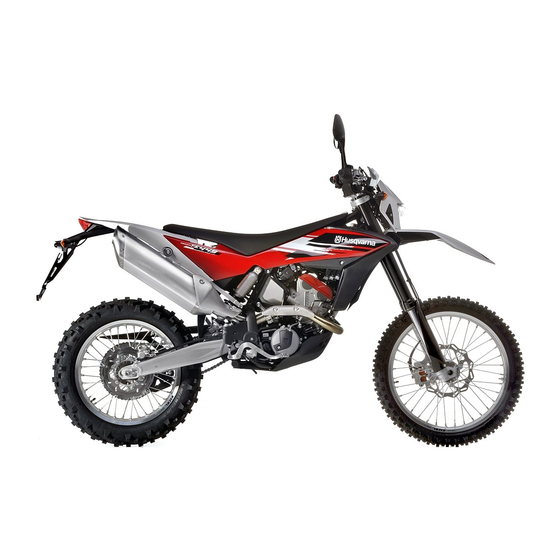
- Page 8 MOTORCYCLE OVERALL VIEW - TE SPECIFICATIONS - OPERATION - MAINTENANCE EN - 8...
- Page 9 LEGEND 1. Front wheel 2. Front brake disc 3. Front brake calliper 4. Front fork 5. Gear shift pedal (the first gear is engaged by pushing lever downwards; for other gears push it upwards. The neutral gear is between the first and second gear) 6.
- Page 10 MOTORCYCLE OVERALL VIEW - TC - TXC SPECIFICATIONS - OPERATION - MAINTENANCE EN - 10...
- Page 11 LEGEND 1. Front wheel 2. Front brake disc 3. Front brake calliper 4. Front fork 5. Gear shift pedal (the first gear is engaged by pushing lever downwards; for other gears push TXC TC it upwards. The neutral gear is between the first and second gear) 6.
- Page 12 CONTROLS WARNING*: Do not overfill the tank. Re- FUEL fer to the lower mark on filler. After Recommended fuel: premium grade FUEL TAPS LEADED petrol with octane rating of 95 or refuelling, make sure the tank cap (2) higher. is closed securely. The two screw taps (1) positioned on tanks left rear side, Note*: If the engine "knocks", change shall always be left in fully OPEN position.
- Page 13 SIDE STAND TE-TXC: COLD START A side stand (1) is supplied with every motorcycle. Periodically check the side stand (see “Scheduled Main- tenance Chart”); make sure that the springs are not dam- TE-TXC: WARNING*: The stand is designed to aged and the side stand freely moves. If the side stand is These models feature an automatic starter positioned support the WEIGHT of the MOTORCY- noisy, lubricate the fastening pivot (A).
- Page 14 SW for the first 2 seconds; 3) the display will now alternate between “Km/h” and case, contact your HUSQVARNA dealer. after the check routine, the dashboard shows the last “Mph Miles”, push the SCROLL button (A) again while planned function.
- Page 15 4- SPEED / LAP TIMER (STP) 5- SPEED (figure 5) 2- SPEED / CLOCK (figure 2) (figure 4) - SPEED: speed - maximum value: 299 Km/h or 299 mph - SPEED: speed - maximum value: 299 Km/h or 299 mph; - CLOCK: clock - reading from 0:00 to 23:59:59.
- Page 16 THROTTLE CONTROL FRONT BRAKE CONTROL The throttle twistgrip (1) is located on the right-hand side The brake control lever (2) is located on the right-hand of the handlebar. The position of the throttle control can side of the handlebar. The position of the control on han- be adjusted by loosening the two retaining screws.
- Page 17 STEERING LOCK (TE) RIGHT-HAND HANDLEBAR SWITCH LEFT-HAND HANDLEBAR SWITCH (TE) The right-hand switch features the following controls: The motorcycle is equipped with a steering lock (1) on The left-hand handlebar switch contains the following the R.H. side of the steering head tube. (TE-TXC) commands: To lock it, proceed as follows:...
- Page 18 ENGINE STOP BUTTON (TC) CLUTCH CONTROL REAR BRAKE CONTROL The hydraulic clutch control lever (1) is located on the left- Engine stop push-button (1) is located on handlebar left- The rear brake control (1) is placed on the right-hand hand side of the handlebar and is protected against dirt. hand side.
- Page 19 INSTRUCTIONS FOR USING THE MOTORCYCLE GEAR SHIFT CONTROL INSTRUCTIONS FOR RUNNING-IN The exclusivity of the design, coupled to the high quality The lever (1) is placed on the left-hand side of the en- NOTE*: If you are not familiar with the of the materials used and the accuracy of the assembly, gine.
- Page 20 TROUBLESHOOTING The engine knocks - excessive carbon deposit on the piston crown, or in the The following list is used for troubleshooting and to find combustion chamber: clean the necessary remedies. - faulty spark plug or wrong heat rating: replace The engine does not start The alternator fails to charge, or its charge is insufficient - the starting procedures are not correctly followed: fol-...
- Page 21 ENGINE STARTING (TE-TXC) With cold engine, i.e., after the motorcycle has not been used for a while or in low ambient temperatures, operate in the following manner: 1) pull clutch lever (1) and hold it in place; 2) shift gear pedal (2) to neutral position; 3) press the starter button (3), then release clutch le- ver (1).
- Page 22 ENGINE STARTING (TC) With cold engine, i.e., after the motorcycle has not been used for a while or in low ambient temperatures, operate in the following manner: 1) Pull starter knob (1); 2) Pull clutch lever (2) and hold it in place; 3) Shift gear pedal (3) to neutral position;...
- Page 23 STOPPING THE MOTORCYCLE AND THE ENGINE - Close the throttle (1) completely in order to slow down the motorcycle. - Apply both front (2) and rear (3) brakes while down- shifting (for fast deceleration, press firmly on both brake pedal and lever). - When stopped, pull the clutch lever (4) and shift gear lever (5) into the neutral position.
- Page 24 ENGINE EMERGENCY STOP (TE) OIL LEVEL CHECK WARNING - Press the red button (6) to stop the engine. Oil level depends on oil temperature. The higher the temperature, the higher the oil level inside oil sump. Should oil level TE - TXC be checked with the engine cold or after short runs, wrong readings may be taken, with consequent wrong topping-up.
- Page 25 ENGINE OIL REPLACEMENT AND MESH FILTERS-FILTER WARNING - loosen the two caps (4), and remove the two mesh CARTRIDGE CLEANING OR REPLACEMENT Start the engine to allow the oil to reach filters (5) and (6); all the points of the engine and check - check for O-rings (7) conditions.
- Page 26 Note *: COOLANT LEVEL CHECK COOLANT REPLACEMENT Difficulties may arise in eliminating coolant from painted WARNING*: Coolant shall be replaced Check level (1) inside left radiator, with the engine cold surfaces. If this occurs, wash off with water. with cold engine and coolant. and the vehicle in vertical position.
- Page 27 - Pour the necessary quantity of coolant in the radiator then warm up the engine in order to eliminate any possible air bubbles. - Allow the coolant to cool down then remove cap (2) and check the level as explained under “Coolant level check”.
- Page 28 WARNING*: Operation with damaged THROTTLE CONTROL CABLE ADJUSTMENT throttle control cable could result in an To check the correct adjustment of the throttle control unsafe riding condition. cable, operate as follows: - loosen screws (1) and remove protective cap (2); - turn throttle twistgrip (3) and make sure that there is a clearance of approx.
- Page 29 WARNING*: Exhaust gas contains poi- SPARK PLUG CHECK IDLE ADJUSTMENT sonous carbon monoxide. Never run the Adjust the carburettor with warm engine and with the Spark plug electrodes gap shall be 0.7 - 0.8 mm (0.028 engine indoors. throttle control in closed position. Proceed as follows: ÷...
- Page 30 CAUTION*: Carefully change the spark To remove spark plug, proceed as follows: plug, if necessary, using one having the - remove the air filter cover; same rating. - disconnect connector (1) on engine left side; - on engine right side, undo screw (2) using an 8 mm wrench;...
- Page 31 AIR FILTER CHECK - release retaining clips (4), and slide filter (5) out of vehicle right side, taking special care not to damage - Turn pin (1) counter clockwise and remove saddle the two retaining hooks; from central retaining screw; - remove right-hand side panel (2) by loosening the five screws (3) using an 8 mm wrench;...
- Page 32 - refit all the disassembled parts in reverse order, mak- STEERING ANGLE ADJUSTMENT - widen the two retaining tabs (6) and remove sub- ing sure to position filter sponge (8) with the "TOP" frame (7) with sponge (8); To modify steering angle, turn the adjuster screws posi- wording facing up.
- Page 33 CAUTION*: Brake fluid may cause irrita- The level of the fluid in master cylinder reservoir must checked by the Husqvarna Dealer. tion. Avoid contact with skin or eyes. In never be below the minimum value (2), which can be...
- Page 34 REAR BRAKE PEDAL POSITION ADJUSTMENT REAR BRAKE PEDAL FREE PLAY ADJUSTMENT WARNING*: When the free play requirement is not The position of the rear brake pedal with respect to the Before staring the braking action, rear brake pedal (3) met, the brake pads will be subjected footrest may be adjusted according to individual needs.
- Page 35 Since it is dangerous to operate water and call a doctor if your eyes the motorcycle under such conditions, were exposed. have the brake system immediately checked by the Husqvarna Dealer. SPECIFICATIONS - OPERATION - MAINTENANCE EN - 35...
- Page 36 SUSPENSION NOTES Hereinafter is a general guide for suspension adjustment, Should the fork be too soft or too hard under all adjust- based on the type of ground or use of the motorcycle. ment conditions, check oil level inside fork leg as it could Always start from the suspension standard setting before be too low or too high;...
- Page 37 ADJUSTING THE FRONT FORK b) REBOUND (TC-TXC): LOWER ADJUSTER; TE: TOP ADJUSTER) c) BLEEDING (to carry out after each competition, or monthly). Standard setting: -14 clicks (TC - TXC); Set the motorcycle on a central stand, release the fork a) COMPRESSION (TC-TXC: TOP ADJUSTER; TE: LOWER Standard setting: -14 clicks (TE).
- Page 38 WARNING*: Never disassemble the shock Cartridge: 196 cu.cm (11.96 cu.in) absorber, which contains compressed Fork sleeve: 370 cu.cm (22.58 cu.in) gas. Contact your Husqvarna Dealer for - TE: 670 cu.cm (40.89 cu.in) any major service. B: rear mudguard top height...
- Page 39 ADJUSTING THE SHOCK ABSORBER SPRING PRELOAD - Clean spring (6) lock ring nut (4), and adjuster ring nut (5). - Turn pin (1) counter clockwise and remove saddle - Loosen lock ring nut using a hook wrench or an alu- from central retaining screw;...
- Page 40 ADJUSTING THE SHOCK ABSORBER HYDRAULIC DAMPING and (2) clockwise until reaching fully closed position. CHAIN ADJUSTMENT Then turn them back to the above-mentioned positions. Chain should be checked, adjusted and lubricated as Adjustment of the compression stroke is independent In order to obtain a smooth braking action, turn the ad- per the Maintenance Chart to ensure safety and prevent from the rebound stroke.
- Page 41 If it is not, proceed as follows: by following the instructions given in the Scheduled LUBRICATING THE CHAIN - on the right side, with a 27 mm Allen wrench, loosen Maintenance Chart. Lubricate the chain following these instructions. the locking nut (2) of the wheel axle; - Check front and rear sprockets for damage.
- Page 42 Chain guide slot, chain slider Washing chain without O-rings (TC) Lubricating the chain with O-rings Check the wear of the above-mentioned elements and Wash using petroleum or naphtha. If you use fuel or es- (TE - TXC) replace them when necessary. pecially trichloroethylene, dry and lubricate the chain to Lubricate all metallic and rubber (O-ring) elements using avoid oxidisation.
- Page 43 Note *: REMOVING THE FRONT WHEEL Do not operate the front brake lever when the wheel has Set a stand or a block under the engine and see that the been removed; this causes the calliper pistons to move front wheel is lifted from the ground. outwards.
- Page 44 REASSEMBLING THE FRONT WHEEL Note *: Do not operate the rear brake pedal when the wheel has - Fit wheel hub left spacer (D). been removed; this causes the calliper pistons to move - Insert wheel between fork legs, so as to couple brake outwards.
- Page 45 BRAKES TYRES The key components of the braking systems are: brake Care should be taken to keep the tyres properly inflated. master cylinder with its lever (front) or pedal (rear), See "Technical data" chart at the beginning of the manu- brake lines, calliper assembly and disc.
- Page 46 BRAKE PADS REMOVAL PADS CLEANING - Remove clips (1). Be careful that no brake fluid or any oil gets on brake - Slide out pin (2). pads or discs. Clean off with alcohol any fluid or oil that - Remove pads. inadvertently gets on the pads or disc.
- Page 47 When electrolyte leaks, or other failure of the electrical - remove the battery (1) from its housing. Antidote: system is detected, apply to the HUSQVARNA Dealer. EXTERNAL - Flush with water. If the vehicle remains unused for long periods, it is rec-...
- Page 48 HEADLAMP BULB REPLACEMENT (TE) Proceed as follows to reach the headlamp bulbs: - Loosen upper screw (1) using an 8 mm wrench; - loosen the two lower screws (2) using a Phillips screwdriver; - move headlight unit (3) aside; - release connector (4); - slide off the rubber gaiter (5);...
- Page 49 To replace the parking light bulb (8) extract it from the TURNING INDICATOR BULB REPLACEMENT (TE) TAIL LIGHT (TE) inside cover. - Loosen screw (1) using a Phillips screwdriver; The tail light (1) is a LED light; Replace it when it does - remove lens (2) and replace bulb (3) pushing it inside, Once the bulb has been replaced, reverse the above pro- not function.
- Page 50 REPLACING THE NUMBER PLATE BULB (TE) HEADLIGHT ADJUSTMENT (TE) Beam height can be adjusted as follows: - loosen screw (1) and remove the number plate bulb When checking the proper aiming of the headlight beam: - Work adjuster screw (1); (2) from the mudguard;...
- Page 51 APPENDIX CLEANING LONG PERIOD OF INACTIVITY Before washing the motorcycle, it is necessary to: When the motorcycle is to be stored for a certain period, - remove the chassis lower caps (4); it should be prepared for storage as follows: - duly protect the following parts from water: - Clean the entire motorcycle thoroughly.
- Page 52 Interruttore accensione Controllo funzionalità Comando acceleratore Controllo funzionalità � Serraggio viti e dadi Controllo / serraggio � � Serrature Controllo funzionalità � Comando acceleratore Verifica/regolazione gioco Fascette stringitubo Controllo / serraggio � � Serraggio viti e dadi Controllo / serraggio �...
- Page 53 REASSEMBLING THE FRONT WHEEL ..........44 ALPHABETICAL INDEX REMOVING THE FRONT WHEEL ............43 Page FORK OIL LEVEL ................38 REMOVING THE REAR WHEEL ............44 FRONT BRAKE CONTROL ..............16 REPLACING THE NUMBER PLATE BULB (TE) ........50 ADJUSTING THE FRONT FORK ............37 FUEL ....................12 RIGHT-HAND HANDLEBAR SWITCH ..........17 ADJUSTING THE SHOCK ABSORBER ..........38 FUEL TAPS ..................12...